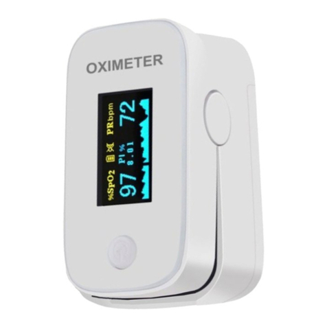
NuvoMed TOS-6/0925 User manual

TOS-6/0925
Blood
Oxygen
Aud
i
ble
Fingertip
Pulse
Oximeter
Instruction
Manual
Please
read
all
instructions
carefully
and
retain
for
future
use

Table
of
Contents
Introduction
3
Know
your
Device
Indications
for
Use
Important
Safety
Information
and
Precautions
Warning
Preparation
4
Parts
Battery
Warning
Instructions
for
Use
5-6
Set
Up
Your
Device
Measurement
Setting
of
Parameter
Care
and
Maintenance
7
Troubleshooting
Specifications
8
EMC
Declarations
9-11
Warranty
Information
12
. . . . .....
. 2
~
. . '
:j

Know
your
Dev
i
ce
Indications
forU
se
Introduction
The
Pulse
Ox
1meter
based
on
all
digital
technology
,
1s
intended
for
noninvasive
spo
t
-check
measurement
of
functional
oxygen
saturauon
of
arterial
hemoglobin
(Sp02)
Advanced
DSP
algonthm
can
minimize
the
mfluence
of
mollon
artifact
and
improve
measurement
accuracy
of
low
perfusion
.
The
Oximeter
can
be
used
to
measure
human
Hemoglobtn
Saturation
and
heart
rate
through
finger
The
product
1s
suitable
for
family,
hospital
(including
d1n1cal
use
in
internisVsurgery
,
Anesthes
ia,
pediatrics.
mtensive
care
and
etc
.)
oxygen
Bar
,
social
medical
organizations
,
physical
care
m
sports
and
etc
Important
Sa
f
ety
lnfonnatlon
a
nd
Precaut
i
ons
•
Do
no
t
attempt
to
serv1ce
the
Pulse
OX1meter.
Only
qualified
serv
i
ce
personnel
should
attempt
any
needed
i
nternal
serv1cmg
.
•
Prolonged
use
or
the
pabenl's
condillon
may
require
changing
the
sensor
site
penodically
Change
sensor
si
te
and
check
skin
1ntegnty
,
circula
t
ory
status
and
correct
alignment
al
least
every
2
hours
•
Sp02
measuremenls
may
be
adversely
affected
in
the
presence
of
hrgh
ambient
light
Shield
the
sensor
area
(with
a
surgical
towel
,
or
direct
sunlight
,
for
example)
if
necessary
•
The
following
reason
w,fl
cause
interference
lo
the
testing
accuracy
of
the
pulse
ox
1
meter
•
High-frequency
electrosurgical
equipment
•
Placement
of
a
sensor
on
an
extremity
w,th
a
blood
pressure
cuff
artenal
cathe
t
er
,
or
intravaSQJlar
hne
•
The
patient
has
hypotension
severe
vasoconstnction
severe
anemia
or
hypothermia
.
•
The
patient
1s
1n
cardiac
arrest
or
ts
m
shock
.
•
Fingerna
il
polish
or
false
fingernails
may
cause
inaccurate
Sp02
readings
.
A
WARN
ING
•
Do
no
t
use
this
device
over
aw
ound
,
as
this
can
cause
further
inJury
.
•
This
device
possible
cause
i
mproper
resu
lt
due
to
e
xt
erna
l
In
terf
erence,
such
as
acceleration
during
transpo
rt
or
transport
m
general
.
•
Do
no
t
attempt
to
modify
this
devtce
tn a
ny
wa
y.
•
Do
not
imm
e
rse
this
de
v
ice
in
w
ater
or
de
an
w
ith
cleaning
products,
alcohol
,
or
solvents
Carefully
follow
deaning
instructions
provided
.
• R
emove
ba
tte
ries
tf
this
device
will
not
be
used
for
three
or
more
months.
•
Ensu
re
tha
t
the
de
v
ice
is
used
in
th
e
enwonment
specified
Ill
the
E
MC
declaration
In
this
IM,
otherw
i
se
,
may
result
in
improper
operation.
•
Use
of
this
device
adJacent
to
or
stacked
wrth
other
de
vt
ce
should
be
avoided
because
ii
could
result
in
Improper
operation.
•
This
electncal
medical
equipment
requires
specific
precautions
reg
arding
etectromagneuc
compatibility
It
must
be
installed
and
used
according
to
the
electromagn
e
tic
in
f
ormabon.
•
Do
no
t
use
this
device
w
here
flammable
gases
or
liquKls
are
presenl
• N
ever
drop
th
ede
vice
.
•
Store
this
device
rn
a
cool,
dry
place
.
Do
not
subject
th
is
device
to
extreme
te
mperatures
,
humldlty,
or
sun
l
ight.
This
device
migh
t
not
meet
perfonn
a
nce
speafications
ifst
ored
or
used
outsi
de
th
e
ranges
specified
in
the
"Specifications·
section
.K
eep
away
from
rain.
Technical
descnptlon
1s
con
ta
ined
in
th
e
1nstruc!Jon
manual
.
• • • • - I
-.
3 · . · -· ·
.;
..
I
•_
• ' ' - - I

Preparat
io
n
Table
3.1.1
Parts
Defin
i
tion
and
Descr
i
ption
TFT Display
Power
Button
Battery
Compartment
Preparation
Name
Power
Button
----
TFT
Display
Battery Indicator 7
\,_,,
,,
'
/,
.,
,,
/
$=--
--
Pulse
Rate
,.
-
,~·
-Perfusion
Hemoglobin
,c
..,~
Saturation Index
.__
Plethysmogram
Note
:
Description
Tum
on
the
machine
Display
the
SP02
/
PR
data
&
Plethysmogram
·-
•
When
battery
power
is
at
lowest
level
,
the
battery
capacity
indicates
symbol
of
•
:3
remind
users
of
replacemen
t
of
battery.
•
The
plethysmograph
can
be
regarded
as
correct
if
the
wave
is
fluctuated
regularly.
BATTERY
WARNING
:
•
Do
not
mix
alkaline,
stand
(carbon-zinc)
and
rechargeable
batteries
(nickel
hydride)
.
•
Do
not
mix
old
and
new
batteries.
•
Non-rechargeable
batteries
are
not
to
be
recharged.
•
Rechargeable
batteries
are
to
be
removed
from
the
unit
being
charged
(if
removable)
.
•
Rechargeable
batteries
are
only
to
be
charged
under
adult
supervision
(i
f
removable).
•
Exhausted
batteries
are
to
be
removed
.
•
The
supply
terminals
are
not
to
be
short-circuited.
•
Only
batteries
of
the
same
or
equivalent
type
as
recommended
are
to
be
used.
•
Batteries
are
to
be
ins
erted
with
the
correct
polarity
(see
diagram)
.

- - -
Instruction
For
Use
Set
Up
Yo
ur
Dev
i
ce
Battery
Installation
1.
Press
the tab
on
the
battery
cover
al
the
back
of
this
device
,
so
as
to
lift
It
up
and
remove
.
2.
Insert
2
AAA
(Included)
alkaline
battenes
according
to
the
+/-
mariungs
.
3
Snap
the
battery
cover
on,
ensuring
It
clicks
Into
place
.
Make
sure
that
the
battery
cover
,s
securely
In
positon
.
NOTE:
When
the
low
battery
symbol
appears
on
saeen
,
tum
off
th
.
is
device
and
follow
the
instructions
above
to
replace
battenes
.
ACAUTION
\.
()
Never
leave
any
low
battery
in
the
battery
compartment
as
it
may
leak
and
cause
damage
to
th,s
device
.
Measurement
Press
power
button
to
tum
the
Pulse
Oximeter
on
.
Put
one
of
fingers
into
rubber
hole
of
the
ox,meter
(it
is
best
to
put
the
finger
thoroughly)
with
nail
surface
upward,
then
releasing
the
clamp
Note
:
The
ox1meter
will
be
automatically
powered
off
when
no
finger
1n
the
device
for
longer
than
16
seconds
.
Sett
i
ng
of
Parameter
When
the
deVJce
1s
under
measunng
interface
,
press
the
power
button
for
1
second
in
order
to
enter1119
into
Menu
Setup
(Figure
1
).
Menu
Setup
Under
the
Menu
Setup
,
user
can
short
press
the
power
button
each
time
moVJng
the
·••
symbol
to
the
back
of
the
SYSTEM
SETTINGS,
ALM
SETTING
,
SP02
SETTING
or
PR
SETTING
for
adjustment.
•
SYSTEM
SETTINGS
(Figure
2)
Move
the
...
symbol
lo
the
back
of
SYSTEM
SETTINGS,
press
the
power
button
for
1
second
going
to
set
the
MODE
DEMO,
BRIGHTNESS
&
RESTORE
Short
press
the
power
button
to
select
the
rt.em
between
MODE
,
DEMO
,
BRIGHTNESS
&
RESTORE
.
MOOE
-
Move
the
...
symbol
to
the
back
of
MOOE
.
long
press
the
power
button
to
select
CONTINUOUS
or
SINGLE
measurement
(
REMARK
:
only
SINGLE
measurement
will
give
audible
read
out
of
the
readings
for
the
user
after
30
seconds
.)
DEMO
-
Move
the
...
symbol
to
the
back
of
DEMO
,
long
press
the
power
button
lo
tum
rt
ON/OFF
.
BRIGHTNESS
-
When
the
...
symbol
shows
behind
"BRIGHTNESS"
,
long
press
the
power
button
each
time
can
change
the
brightness
value
from
1
to
5
RESTORE
-
When
the
...
symbol
shows
behind
"RESTORE"
,
long
press
the
power
button
can
change
lo
"OK"
,
which
causes
the
devtCe
to
restore
factory
data
setting
- - - - , : • I
5 .
' .

Instruction
For
Use
•
ALM
SETTING
(Figure
3)
Move
the
•••
symbol
to
the
back
of
ALM
SETTING
,
press
the
power
button
for
1
second
going
to
set
the
ALM
ALM
•
Move
the
•··
symbol
lo
the
back
of
ALM
,
long
press
the
power
button
lo
tum
it
ON
/OF
F.
(Note
:
If
t
he
measured
value
exceeds
the
maximum
or
min
i
mum
value
of
SP02
or
PR
,
that
value
will
flash
continuously
.)
•
SP02
SETTING
(Figure
4)
Move
the
·•·
symbol
to
the
back
of
SP02
SETTING
,
press
the
power
button
for
1
second
going
to set
the
SP02
ALM
HI
,
SP02
ALM
LO
&+/•.
Short
press
the
power
button
to
select
the
i
tem
between
SP02
ALM
HI
,
SP02
AL
M
LO
&+/
•.
When
the•
symbol
show
behind
the
"+/.
",
press
di
rection
button
for
1
second
to
change
the
·
+·
to
·
.·
or
change
the
·
-·
to
·+
·.
SP02
ALM
HI
-
Move
the
•••
symbol
lo
t
he
back
of
SP02
ALM
HI
With
•+•
sho
ws
on
the
right
side
of+/.,
long
press
the
power
button
each
lime
can
increase
the
value
to
a
higher
value
(until
it
reaches
to
the
highest
).
SP02
ALM
LO•
Move
the
...
symbol
to
the
back
of
SP02
ALM
LO
With
·-·
shows
on
the
right
side
of+/·,
long
press
the
power
button
each
lime
can
reduce
the
va
l
ue
lo
a
lower
value
(until
it
reaches
to
the
lowest
)
•
PR
SETTING
(
Figure
5)
M
ove
the
·•·
symbo
l
to
the
back
of
PR
SETT
I
NG
,
press
the
power
button
for
1
second
going
to
set
the
PR
ALM
HI
,
PR
ALM
LO
&+/•.
Short
press
the
power
button
lo
select
the
i
tem
between
PR
ALM
HI
,
PR
ALM
LO
&+/-
When
the•
symbol
show
beh
i
nd
the·+/.•,
press
direction
button
for
1
second
to
change
the
•
+•
to
•.•
or
change
the
•
•"
to
"+
".
PR
ALM
HI
- M
ove
the
...
symbol
to
the
back
of
PR
ALM
HI.
With
"+"
shows
on
the
right
side
of+/.,
long
press
the
power
button
each
time
can
increase
the
value
to
a
higher
value
(
until
it
re
a
ches
to
the
highest)
.
PR
ALM
LO
-
Move
the
·••
symbol
to
the
back
of
PR
ALM
LO
.
With
·-•
shows
on
the
nght
si
de
of+
/-,
long
press
tlie
power
button
each
time
can
reduce
the
value
lo
a
lower
value
(un
t
il
it
reaches
to
the
lowest
).

Care
and
Maintenance
SYSTE
MSETilN
GS
• M
ODE
CONTI
N
UOUS
•
ALM
SETilNG
ALM
SETTI
NG
DEMO
OFF
SP02
SETTI
NG
ALM
ON
•
BRIGHTNESS
5
PR
SETTI
NG
RESTORE
NO
BEEP
ON
EXIT
B
ACK
EXIT
Figure 1 Fi
Qure
2 Figure 3
SP02 SETilNG
PR
SETTING
SP02
ALM
HI
100 .
PR
ALM
HI
130 .
SP02
ALM
LO
70
PR
ALM
LO
40
+/- + +/. +
BACK
BA
CK
Figure 4 Figure 5
Note
:
1
ALM
=1
second
de
l
ay
after
the
in
correct
result
be
i
ng
detected
.
2.
The
customer
can
preset
the
hm1t
value
to
the
98
or
99
to
check
whether
it
1s
normal
for
ALM
setting
Care
and
Ma
i
nte
n
ance
•
For
regular
maintenance
,
this
device
only
needs
to
be
wi
ped
gently
with
a
soft
,
dry
cloth
.
•
Never
immerse
this
deVIC8
or
any
components
In
water
.
•
Do
not
carry
out
repairs
of
any
ki
nd
yoursel
f. Ifa
defect
occurs,
please
contact
your
local
authonzed
distributor
Use
only
authorized
parts
and
accessories
.
Troubleshooting
Oxyhemoglobin
or
heart
rate
not
shown
nonnally
Reason
:
Finger
is
not
plugged
correcUy
OR
pa
t
ient's
perfusion
is
too
l
ow
to
be
measu
r
ed
.
Solut
i
on
:
Retry
by
plugging
the
finger
OR
try
few
times
,if
you
can
make
sure
about
no
problem
ex1s
t
1ng
in
the
product
Oxyhemoglobin
or
heart
rate
is
shown
unstably
Reason
: F
inger
might
not
be
plugged
deep
enough
OR
finger
is
trembling
or
patien
t
's
body
is
in
movement
status
.
Solution
:
Retry
by
plugging
the
finger
OR
try
to
let
patient
keep
calm
.
Oxyhemoglobin
or
heart
rate
is
abnormal
and
causes
ALM
Reason
:
Finger
is
not
plugged
correcUy
OR
patient's
SP02
&
PR
is
abnormal.
So
l
ution
:
Retry
by
p
lugging
the
finger
OR
go
to
the
hospital
for
further
examination.
The
Oxlmeter
cannot
be
powered
on
Reason
:
Po
w
er
of
ba
tt
enes
might
be
i
nadequate
/
batteries
may
no
t
be
detached
fine
/
batteries
mi
ght
be
installed
not
proper1y
I
oximeter
might
be
damaged
Solut
i
on
:
Replace
battenes
OR
re-
i
nstall
battenes
Screen
shut
down
suddenly
This
device
1s
automatically
po
w
ered
off
when
no
signal
longer
than
16
seconds
.
Note
·
Please
go
to
a
hospital
bmely
for
exact
diagnosis
.
- -
7
- - -

Specifications
Model
TOS-6/0925
--
Dimensions
56mm
(L)
x
30mm
(W)
x
30mm
(D)
Anti-electric
Shock
Type
Internally
Powered
Equipment
Anti-electric
Shock
Degree
Type
BF
Equipment
EMC
TypeB
Mode
of
Operation
Continuous
Operation
Endosure
Degree
of
ingress
protection
:
IP22
•tP22
means
the
outer
body
of
the
product
can
withstand
the
water
dropping
to
the
surface
when
the
body
deviate
15
degree
from
horizontal
surface
.
>---
Power
2
AAA
(
Included)
Power
Consumption
25-
50mA
(
Nonna!
)
Environmental
Operating
Temperature
About
+50-+104°F
I
+10-
+40°C
Storage
Tempera
t
ure
About
...4-+140°F
/
-20-+60
°C
Relative
Humidity
15%
-
95%
non-condensing
/iJr
Pressure
About70Kpato106Kpa
ALM
Limit
Default
Value
Parameter
Value
Hemoglobin
Saturation
Limit:
100
(U
pper
)
94
(Bottom)
Pulse
Rate
Limit:
130
(Upper)
50
(
Bottom
)
Electronics
Parameters
Parameter
Value
Hemoglobin
Saturation
Display
0-99%
>-
·-
Pulse
Rate
Display
30-250BPM
Reso
lution
Hemoglobin
Saturation
1%
Pulse
Rate
1
BPM
Measure
Accuracy
·
Hemoglobin
!
2%
(70%
-100
%)
Saturation
Unspecified
(<
70
%)
Pulse
Rate
!
3BPM
Display
0-20%
Pl
..............
Resolution
0.1%
---
-
--
-
Measure
Accuracy
0-1%
:0.
1%
Probe
OLEO
Specification
Wave
Length
Radiant
Power
Red
660±2
nm
1.
8mW
Infra
RED
905±2
nm
2.0mW
-. . ' 8

EMC
Declaration
Manufacture
r's
Oeclarallon
of
the
EMC
Guidance
and
manufadurer's
declaretJOn
-
electromagnellc
8ffllSSIOII
..lo(
all
EQUIPMENT
ANO
SYSTEMS
Fu,geftip
Pulse
Oxlmeter
JS
inlended
for
use
in
lhe
eledromagnolle
tlTM)Oment
Sl)8cified
be'ow
The
user
ol
lhis
cleV10e
should
assure
lhat
,t
ls
used
in
5IJCh
an
erriironment.
Emissions
Test
Compnance
Elec:1n>magnetlc
Environment
•
Gu
i
dance
RF
EmlSSions
CISPR
11
Group
1
This
device
uses
RF
energy
only
lo(
11$11temal
function
Therafore,
11s
RF
8IMSIOllS
..,_
________
-
are
-.,,ry
low
and
are
not
hltely
ID
cause
a
ny
,nlerfere
n
c:e
111
nea
rb
y
elecvooic
RF
EmlSSIOlls
CISPR
11
Class
B
This
de'l!Ce
,s
suita
b
le
lor
use
In
al
estabhshmenlS
lndud,ng
dome$1Jc
estabishmenls
811d
lllose
di'8Clly
connected
10
lh
e
pubic
low•\IOllage
po-
supply
Ha
rmonic
Emlss.ons
NIA
netwolk
lhat
$Uppl8S
bullcfllQS
used
for
domesbt
purposes
IEC6100().3-2
Voltage
ftuauabons
I
NIA
ltd(e,
emtSSIOns
IEC
6100().
3-3
Immun
i
ty
Tes
t
rec
60601
Compliance
Level
EltctromlgntticEnvlron~nl•
Ttsl
level
Gu
i
dance
Eledroslabe
:t 8kV
conlacl
:t8kVconlad
Floors
should
be
wood,
concrele
Of
ceramc
ble
II
llools
are
dischalge(ESD)
COW/red
W1th
synthetic
ma1enal.
the
relative
hUfflldJty
IECSI000-4-2
t l5kVa,r :t
15
k
Vw
should
be
a1
lea
st
30
%.
Eledloslallc
.!
2kV
for
power
supply
NIA
M
am
power
quality
shOIAd
be "81
ol
a
transaenl
/
buts1
II/Ml$
tyl)ICll
oonvnen,al
Of
hospital
enwonment
1EC6l000~
• lkV
for
lnpul/output
-
-------
Surge
! 1
kV
kw
d1fferenbal
mode
NIA
____
1EC
61000-4-5
.t
2kV
common
mode
VOllage
dips,
short
0
,-.
UT,
0.5
cyde
g)
Alo•
NIA
Manspc7"9f
quality
shouk!
be
N Iola
lypal
c:ommerdal
Of
llllerrupUons
and 4
5•
90•,
135•
180'
225'
hospctal
environment
If
lhe
use<
of
!hos
de'l\ce
requires
.orlagevanations
27
0°
a
nd
315"
0%UT I controod
operabon
dunng
power
mallS
onlelTIJl)bons
rt
1s
on
power
supply
cyc;le
and
70
%
UT.
25/30
recoovnendOd
Iha
!this
device
be
powered
l'rom
an
lf'IPUI
l,nes
IEC
cyc;1es
a1
o•
unin1em,pt,ble
power
supply
or•
ballety.
61000-4-11
0
'4
UT,
250/300
cyde
Po,,ier
frequency
30f.Jm
30Mn
P-
frequency
magnebc
fields
should
be
al
lfflls
(5CM'60
Hz)
charaderisbc
ole
typ,cei
locabon
111
a
typ,cal
al1'111'1left>al
Of
magneoc
field
hoSpital
enwonment
IEC
61000-4-3
N
OTE
UT
II
lhe
a
c.
mains
vollage
pn0f
to
eppbcabon
of
the
lest
level
-.9'
..
' . . ' .
. .
. .

EMC
Declaration
Guidance
and
manufacturers
declaration
-
electromagnetic
immunity
-for
EQUIPMENT
and
SYSTEM
that
are
not
LIFE-SUPPORTING
This
device
1s
intended
for
use
In
the
electromagnetic
environment
specified
below
The
user
of
this
deVIC8
should
assure
that
it
is
used
in
such
an
environment.
Immunity
Test
tEC
60601
Compliance
Electromagnetic
Environment
•
Guidance
Test
level
Level
Conducted
RF
IEC
3
Vnns
150
N/A
Portable
and
mobile
RF
communications
equipmen
t
should
be
61000-4-6
kHzto80
used
no
doser
to
any
part
of
theA310
Fingertip
Pulse
Ox1meter
,
MHz
including
cables
,
than
the
recommended
separation
distance
calculated
from
the
equation
applicable
to
the
frequency
of
the
..
Radiated
RF
IEC
6Vnnsin
Recommended
separation
distance
61000-4-3
IS
M
band
between
ti
1!.s,,r,;
150
kHz
to
8 V,
0MHz
80MHz
to
d=(
3'5
lvP
27GHz
E,
80
M
Hz
to
800
MHz
J I7 J
v'P
£,
800
MHz
to
25
GHz
Where
pis
the
maximum
output
power
rating
of
the
transmitter
in
watts
(W)
according
to
the
transmitter
manufacturer
and
dis
the
recommended
separation
distance
in
metres
(m)
.b
10V/m
Field
strengths
from
fixed
RF
transmitters
,
as
determ
i
ned
by
an
electromagnetic
site
survey
,a
should
be
fess
than
the
compliance
level
in
each
frequency
range
.b
In
t
erference
may
occur
In
the
vicinity
or
equipment
marked
with
the
following
symbol.
.
'
NOTE
1
At
80
MHz
and
800
MHz
.
the
higher
frequency
range
applies
.
NOTE
2·
These
guidelines
may
not
apply
in
all
situations
.
8ectromagnetic
Is
affected
by
absorption
and
reflection
from
structures.
objects
and
people
a
Field
strengths
from
fixed
transmitters.
such
as
base
stallons
for
radio
(cellular/cordless)
te
lephones
and
land
mobile
radios
,
amateur
rad10
,
AM
and
FM
radio
broadcast
and
TV
broadcast
cannot
be
predicted
lheorellcally
with
accuracy
.
To
assess
the
electromagne11c
environment
due
to
fixed
RF
transmitters.
an
electromagnetic
site
survey
should
be
considered.
If
the
measured
field
strength
in
the
locabon
in
Which
the
A310
F
ing
ertip
Pulse
Oximeter
Is
used
exceeds
the
applicable
RF
compliance
level
above
,
the
A310
Fingertip
Pulse
Oximeter
should
be
observed
to
verify
normal
operation
If
abnormal
performance
1s
observed
,
additional
measures
may
be
necessary
,
such
as
reorienting
or
relocating
the
A310
Flngerup
Pulse
OX1meter
.
b.
Over
the
frequency
range
150
kHz
lo
80
MHz,
field
sffengths
should
be
less
than
3V/m
.

EMC
Declaration
Recommended
sep
a
ration
distances
between
portable
and
mobile
RF
communications
equ
i
pment
and
the
EQUIPMENT
or
SYST
EM -
for
E
QUIPMENT
and
SYST
EM
S t
hat
are
not
LIFE-
SUPPORTI
NG
Recommended
separation
distances
between
portable
and
mobile
RF
commun
i
cations
equipment
and
this
device.
This
dev
i
ce
is
intended
for
use
in
an
electromagnetic
environment
in
which
radiated
RF
disturbances
are
controlled
.
The
user
of
this
device
can
help
prevent
electromagnetic
interlerence
by
maintain
i
ng
a
minimum
distance
between
portable
and
mobile
RF
communications
equipment
(t
ransmitters)
and
this
device
as
recommended
below
,
according
to
the
maximum
output
power
of
the
communications
equipment.
Rated
maximum
Separation
di
stance
according
to
frequency
of
transmitter
output
of
transm
i
tter
.__
--
-
w
150
kHz
to
80
MHz
80
MHz
to
800
MHz
800
MHz
to
2.7
GHz
d
ee
[3·5]J P ti
cJ.s
J
J?
ti
r-21#
,,
'
£1
/:.
1
- -
0.01
I 0.
12
0.23
0.1 I 0.
38
0.
73
1 I 1.2
2.3
10
I 3.8 7.3
100
I
12
23
For
transmitters
rated
at
a
maximum
output
power
not
listed
above
the
recommended
separation
di
stance
d
in
meters
(m)
can
be
estimated
using
the
equation
applicable
to
the
frequency
of
the
transmitter
,
where
P
is
the
maximum
output
power
rating
of
the
transmitter
in
watts
0N)
according
to
the
transmitter
manufacturer
.
NOTE
1:
At
80
MHz
and
800
MHz
,
the
separation
distance
for
the
higher
frequency
range
applies.
NOTE
2:
These
guidelines
may
not
apply
in
ail
situations
.
Electromagnetic
propagation
is
affected
by
absorption
and
reflection
from
structures
,
objects
and
people
.

Warranty
Information
WARRANTY
DURATION
:
All
materials
and
workmansh
ip
are
warranted
to
the
orig
i
nal
consumer
purchaser
for
a
period
of
ni
nety
(
90)
days
from
the
orig
i
nal
purchase
date
.
WARRANTY
COVERAGE
:
This
product
is
warranted
against
defective
materials
or
workmansh
ip.
Th
is
warranty
is
void
1f
the
product
has
been
damaged
by
accident,
in
shipment
,
unreasonable
use
,
misuse
,
neglect
,
improper
service
,
commercial
use
, r
epa
i
rs
by
unauthorized
personnel
or
other
causes
not
aris
i
ng
out
of
defects
in
materials
or
workmansh
ip.
This
warranty
does
not
cover
the
fo
ll
owing
which
may
be
supp
li
ed
with
product
,
including
but
not
limited
to
;
LCD
Screens
,
gla
ss
parts
,
lenses
,
bu
l
bs
etc
.
Th
is
warranty
is
effective
on
lyif
the
product
is
purchased
and
operated
in
USA
,
and
does
not
extend
to
any
units
wh
i
ch
have
been
used
in
violation
of
written
i
nstructions
furn
i
shed
by
manufacturer
or
to
units
wh
i
ch
have
been
altered
or
mod
i
fied
or
,
to
damaged
produc
ts
or
parts
thereof
which
have
had
the
serial
number
removed
,
altered
,
defaced
or
rendered
i
llegib
le
WARRANTY
PERFORMANCE
:
During
the
above
90
day
warranty
period,
a
product
with
a
defe
ct
will
be
either
repaired
or
replaced
with
a
recond
i
tioned
comparable
model
(
at
manufacturer's
option
).
The
repaired
or
replacement
product
will
be
in
warranty
for
the
balance
of
the
90
day
warranty
period
and
an
additional
one-month
period
.
No
charge
will
be
applicable
for
such
repa
ir
or
replacement.
SERVICE
AND
REPAIR
: If
serv
i
ce
Is
required
for
th
is
product
,
you
should
first
contact
Nuvomed
Inc
.
Customer
Service
at
or
by
ca
lli
ng
Toll-Free
Numbe
r 1
(
877
)
612
5619
,
Monday
to
Friday
10am
to
6pm
EST
.
NOTE
:
Manufacturer
cannot
assume
responsibility
for
loss
or
damage
during
i
ncoming
shipmen
t.
As
a
precautionary
measure
,
carefully
package
the
product
for
shipment
,
and
I
nsure
it
with
the
carrier
.
Be
sure
to
enclose
the
following
details
with
the
product:
your
full
name
,
return
address
and
daytime
phone
number,
a
note
describing
the
problem
you
experienced
, a
copy
of
your
sales
receipt
or
other
proof
of
purchase
to
determine
warranty
status
. C.O.D.
shipments
cannot
be
accepted
.
Th
is
manufacture
r'
s
product
warranty
extends
to
the
original
consumer
purchaser
of
the
product
Neither
the
retailer
nor
any
other
company
involved
in
the
sale
or
promotion
of
th
is
product
is
a
co-
warrantor
of
this
manufacturer
warranty
.
WARRANTY
DISCLAIMERS
:
This
warranty
is
in
heu
of
all
warranties
expressed
or
implied
and
no
representative
or
person
is
authorized
to
assume
for
manufacturer
any
other
li
ability
in
connection
with
the
sale
of
our
products
.
There
shall
be
no
claims
for
defects
or
failure
under
any
theory
of
tort,
contractor
commercial
law
including
but
not
limited
to
,
neg
li
gence
,
gross
negligence
,
strict
liability
,
breach
of
warranty
and
breach
of
contract.
Under
no
circumstances
will
Manufacture
r'
s /
Distributor's
maximum
liab
ili
ty
exceed
the
retail
value
of
the
product.
12
I
Other manuals for TOS-6/0925
1
Table of contents
Other NuvoMed Medical Equipment manuals
Popular Medical Equipment manuals by other brands

Glooko
Glooko Transmitter Instructions for use

Click Medical
Click Medical RevoLock quick start guide

Whitehall Manufacturing
Whitehall Manufacturing Little Splint Instructions for operation and care

Ossur
Ossur ICEROSS I-813120 Instructions for use

Leckey
Leckey Advance Bath Chair user manual

Maquet
Maquet SERVO-i V3.1 user manual