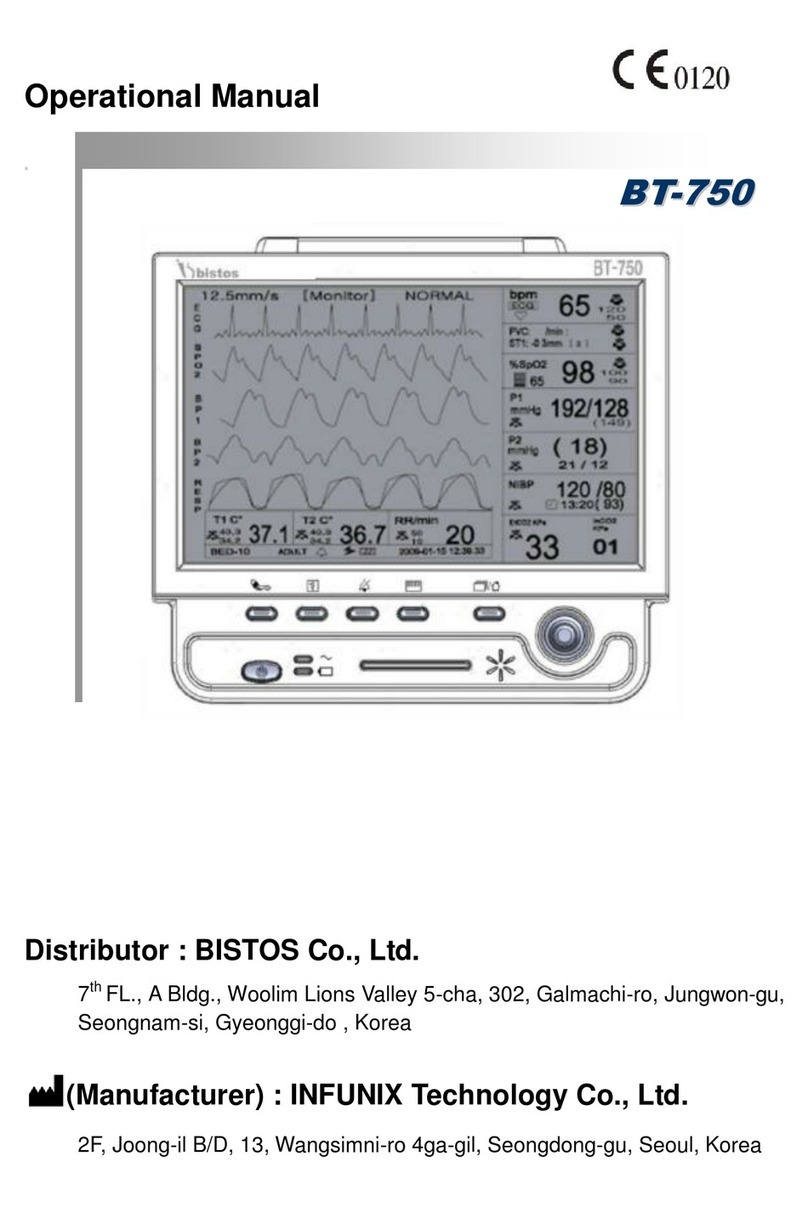
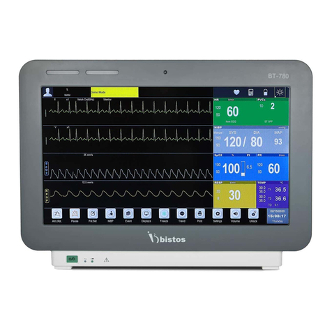
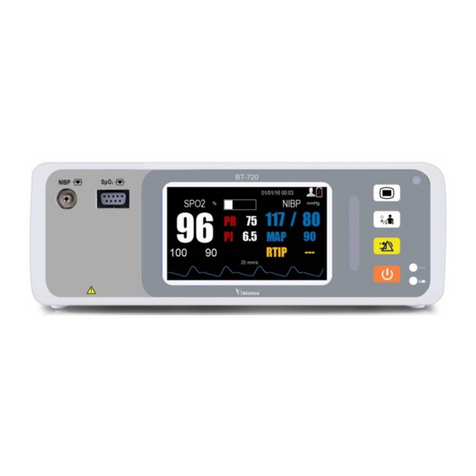
Bistos BT-700 User manual

BT-700
Patient Monitor
OPERATOR MANUAL
Keep this manual for future reference
P/N: 700-ENG-OPM-EUR-R02
BT-700

BT-700 Operator Manual 2
P/N : 700-ENG-OPM-EUR-R02
Bistos Co.,Ltd.
2018,03
Proprietary Material
Information and descriptions contained in this manual are the property of Bistos
Corporation and may not be copied, reproduced, disseminated, or distributed without
express written permission from Bistos Corporation.
Information furnished by Bistos Corporation is believed to be accurate and reliable.
However, no responsibility is assumed by Bistos for its use, or any
infringements of patents or other rights of third parties that may result from its use.
No license is granted by implication or otherwise under any patent or
patent rights of Bistos
Revision 02
Mar,2018
Copyright © Bistos Corporation 2011. All rights reserved.
7th FL., A Bldg., Woolim Lions Valley 5-cha, 302,
Galmachi-ro, Jungwon-gu, Seongnam-si, Gyeonggi-do, Korea
Telephone: ++82 31 750 0340
Fax: ++82 31 750 0344
Printed in Korea

BT-700 Operator Manual 3
P/N : 700-ENG-OPM-EUR-R02
Bistos Co.,Ltd.
2018,03
Table of Contents
1. SAFETY ..............................................................................5
1.1 Instructions for the Safe Operation and Use of the BT-700 ........................... 5
1.2 Warnings.......................................................................................................... 5
1.3 Cautions........................................................................................................... 6
1.4 Definitions of Symbols.................................................................................... 9
2. INTROCUTION...................................................................10
2.1 Brief Device Description & Intended purpose .............................................. 10
2.2 Options and Accessories.................................................................................11
3. INSTALLATION..................................................................12
3.1 Description of the BT-700 Front Panel.......................................................... 12
3.2 Description of the BT-700 Side Panel ........................................................... 12
3.3 Description of the BT-700 Rear Panel........................................................... 13
3.4 Power On and Probe Connection................................................................... 13
4. BT-700 OPERATION..........................................................14
4.1 Factory Setting............................................................................................... 14
4.2 BT-700 Display Screen.................................................................................. 14
4.2.1 Parameter Frame............................................................................. 16
4.2.2 SpO2 Frame.................................................................................... 16
4.2.3 Pulse Rate Frame............................................................................ 16
4.2.4 Alarm limits Frame......................................................................... 16
4.2.5 Plethysmograph frame.................................................................... 16
4.2.6 Temperature frame.......................................................................... 16
4.2.7 SpO2 trend frame and Pulse rate trend frame................................. 16
4.2.8 Alarm message & Time frame........................................................ 17
4.2.7 Status frame.................................................................................... 17
4.3 BT-700 Controls and Indicators..................................................................... 17
4.4 BT-700 Controls Knob .................................................................................. 18
4.5 Menu tree....................................................................................................... 18
4.6 Data saving.................................................................................................... 19
4.6.1 How to save data............................................................................. 19
4.6.2 Trend data....................................................................................... 19
5. OPERATION.......................................................................20
5.1 Electromagnetic Interface.............................................................................. 20
5.2 Basic operation.............................................................................................. 20
5.3 Detail Procedure............................................................................................ 21
6. ALARMS AND MESSAGES...............................................22
6.1 Alarms priority ............................................................................................ 22
6.2 Alarms silence period.................................................................................... 22
6.3 Alarms volume control.................................................................................. 22

BT-700 Operator Manual 4
P/N : 700-ENG-OPM-EUR-R02
Bistos Co.,Ltd.
2018,03
7. CLEANING AND DISINFECTION ......................................23
7.1 Monitor.......................................................................................................... 23
7.2 Sensors........................................................................................................... 23
8. TROUBLESHOOTING AND MAINTENANCE ...................25
8.1 Sensors........................................................................................................... 25
8.2 Battery Disposal and Handling...................................................................... 25
8.3 Maintenance .................................................................................................. 25
8.4 Troubleshooting............................................................................................. 25
9. SPECIFICATION ................................................................26

BT-700 Operator Manual 5
P/N : 700-ENG-OPM-EUR-R02
Bistos Co.,Ltd.
2018,03
Section 1
Safety
1.1 Instructions for the Safe Operation and Use of the
BT-700
Examine the monitor and any accessories periodically to ensure that
the cables, line cords, transducers, and instruments do not have visible
evidence of damage that may affect patient safety or monitoring
performance. The recommended inspection interval is once per week
or less. Do not use the monitor if there is any visible sign of damage.
Only the AC line cord supplied with the BT-700, or its equivalent, is
approved for use with the Unit.
Do not attempt to service the BT-700 monitor. Only qualified service
personnel should attempt any needed internal servicing.
The BT-700 is not specified or intended for operation during the use of
defibrillators or during defibrillator discharge.
The BT-700 is not specified or intended for operation in the presence
of electrosurgical equipment.
The BT-700 is not specified or intended for operation in conjunction
with any other type of monitoring equipment except the specific
devices that have been identified for use in this Operator’s Manual.
Perform periodic safety testing to insure proper patient safety. This
should include leakage current measurement and insulation testing.
The recommended testing interval is once per year.
1.2 Warnings
WARNING: EXPLOSION HAZARD — Do not use the BT-700 in a
flammable atmosphere where concentrations of flammable anesthetics or
other materials may occur.
WARNING: Be informed that it may cause serious injury or death to the
patient, property damage, material losses against the “Warning" sign.
CAUTION: Be informed that it may cause no harm in life but lead to
injury against the“ Caution" sign.

BT-700 Operator Manual 6
P/N : 700-ENG-OPM-EUR-R02
Bistos Co.,Ltd.
2018,03
1.3 Cautions
WARNING: Do not connect to an electrical outlet controlled by a wall
switch.
WARNING: SHOCK HAZARD — Do not attempt to connect or
disconnect a power cord with wet hands. Make certain that your hands are
clean and dry before touching a power cord.
WARNING: Use only patient cables and transducers supplied with the
monitor. Use of any other patient cables may result in out-of-specification
performance and possible safety hazards.
CAUTION: Keep the operating environment free of dust, vibrations,
corrosive, or flammable materials, and extremes of temperature and
humidity. The unit should be kept clean and free of transducer gel and
other substances.
CAUTION: The relevant law restricts this device to sale by or on the order
of a physician.
CAUTION: When installing the unit into a cabinet, allow for adequate
ventilation, accessibility for servicing, and room for adequate visualization
and operation.
CAUTION: Do not operate the unit if it is damp or wet because of
condensation or spills. Avoid using the equipment immediately after
moving it from a cold environment to a warm, humid location.
CAUTION: Never use sharp or pointed objects to operate the front-panel
switches.
WARNING: Do not contact RS-232C port and patient at the same time.
WARNING: AC/DC Adaptor should use appointed product.
WARNING: SHOCK HAZARD — BT-700 doesn't have protection
against the burn injury caused by RF Surgical equipment. Do NOT use
this product along with RF Surgical equipment.
WARNING: The power receptacle must be a two wire non-grounded
outlet.

BT-700 Operator Manual 7
P/N : 700-ENG-OPM-EUR-R02
Bistos Co.,Ltd.
2018,03
CAUTION: Accessory equipment such as RS-232 and USB connected to
the analog and digital interfaces must be certified according to the
respective IEC standards ( e.g. IEC 950 for data processing equipment and
IEC 601-1 for medical equipment ). Furthermore all configuration shall
comply with the system standard EN 60601-1-1:2001 If in doubt, consult
the technical service department or your local representative.)
CAUTION: Do not autoclave or gas sterilize the monitor or any
accessories. Follow cleaning and disinfection instructions in Section 7 of
this manual.
CAUTION: Do not immerse the SpO2 sensor in liquid. When using
solutions, use sterile wipes to avoid pouring fluids directly. Follow
cleaning and disinfection instructions in Section 7 of this manual.
CAUTION: If the equipment use in area where the integrity of the
external protective conductor in the installation or its arrangement is in
doubt, equipment shall be operated from its internal electrical source when
the optional battery is selected.
CAUTION:
-The equipment conforms to Class A according to IEC/EN 60601-1(Safety
of Electric Medical Equipment)
- This equipment conforms to Level B according to IEC/EN 60601-1-2
(Electromagnetic Compatibility Requirements)

BT-700 Operator Manual 8
P/N : 700-ENG-OPM-EUR-R02
Bistos Co.,Ltd.
2018,03
General Precaution on Environment
Do not keep or operate the equipment under the environment listed below.
Avoidplacing in an area
exposed tomoisture.Do not
touchtheequipmentwith wet
hand.
Avoidexposureto
directsunlight
Avoid placing in an area
where there is a high
variation of temperature.
Operating temperature
ranges from 10°C to 40°C.
Operating humidity ranges
from 30% to 85%.
Avoid in the vicinity
of Electric heater
Avoid placing in an area
where there is an
excessive humidityrise or
ventilation problem.
Avoid placing in
an area where
thereisanexcessive
shockorvibration.
Avoid placing in an area
where chemicals are
stored or where there is in
danger of gas leakage.
Avoid dust and
especially metal
material into the
equipment.
Do not disjoint or
disassemble the equipment.
BISTOS Co., Ltd. does not
take responsibility of it.
Power off when
the equipment is
not fully installed.
Otherwise, the
equipment could
be damaged.

BT-700 Operator Manual 9
P/N : 700-ENG-OPM-EUR-R02
Bistos Co.,Ltd.
2018,03
1.4 Definitions and Symbols
Symbol
Description
Requirements
Power On/Off Button IEC TR 60878
This symbol identifies a safety note. Ensure you
understand the function of this control before
using it. Control function is described in the
operator’s manual.
IEC 60601-1
External Signal IN/OUT Port IEC TR 60878
Defibrillation-proof type BF applied part IEC60601-1
IPX7 IPX7 Water-proof (Temperature, type rectal) IEC60529
IPX2 IPX2 Water-proof (SpO2 sensor ) IEC60529

BT-700 Operator Manual 10
P/N : 700-ENG-OPM-EUR-R02
Bistos Co.,Ltd.
2018,03
Section 2
Introduction
2.1 Brief Device & Intended purpose
The BT-700 is a Patient monitor. It measures the SpO2, pulse rate and temperature. It
provides continuous and noninvasive information on two important physiological
parameters: arterial blood oxygen saturation and pulse rate. This information is
obtained through measurement of light intensity transmitted across the finger at two
distinct wavelengths, in the red and near-infrared regions of spectrum. This monitor
measures functional saturation – oxygenated hemoglobin expressed as a percentage of
the hemoglobin that can transport oxygen. It does not detect significant amounts of
dysfunctional hemoglobin, such as carboxyhemoglobin or methemoglobin. In contrast,
hemoximeters such as the IL482 report fractional saturation – oxygenated hemoglobin
expressed as a percentage of all measured hemoglobin, including measured
dysfunctional hemoglobins. To compare functional saturation measurements to those
from an instrument that measures fractional saturation, fractional measurements must
be converted as follows the temperature is measured in the patient’s rectal. The
resistance value of the temperature sensor is changed for the patient’s rectal
temperature. BT-700 measures it’s resistance, and calculates the temperature.
BT-700 has the Auto-calibration functions for each other patient. Internal calibration
function starts calibrating when the patient is monitored.
This device is for use only by trained medical personnel located in hospitals, clinics,
doctor’s offices.

BT-700 Operator Manual 11
P/N : 700-ENG-OPM-EUR-R02
Bistos Co.,Ltd.
2018,03
2.2 Options and Accessories
Basic Accessories
The following are the basic specifications. To open the packaging to make sure that
the following accessories.
①BT-700 Body : 1 ea
②Re-usable SpO2 sensor probe : 1 ea
③SpO2 Extension cable : 1 ea
④Power adapter : 1 set
⑤Power Cord : 1 ea
⑥Operator manual : 1 ea
Option Accessories
The following is optional. If you wish to purchase, please contact our office.
①Disposable SpO2 sensor probe
②Temperature sensor probe (Type : Rectal)
③I-V holder
WARNING:
- The Temperature sensor of BT-700 is used only rectal type.
- The Temperature sensor of BT-700 is calibrated with YSI temperature
sensor.
WARNING:
- BT-700 and The SpO2 sensor are certificated with international standards.
- The SpO2 sensor of BT-700 is type nellcor SpO2 sensor.
- The extension cable of BT-700 is available in the BT-700 only. If you use a
different cable, check the compatibility
WARNING:
- Power adaptor :
Only use the ‘Power Bridge Corporation – JMW110 9Vdc, 1.5A’

BT-700 Operator Manual 12
P/N : 700-ENG-OPM-EUR-R02
Bistos Co.,Ltd.
2018,03
Section 3
Installation
3.1 Description of the BT-700 Front Panel
Fig. 3.1 BT-700 Front Panel
①Power On/Off Button
②Power Indicating LED ( AC: Green / Battery:Orange)
③TFT-Color LCD
④Mode Change Button
⑤Trend Save Button
⑥Alarm On/Off Button
⑦Bright Button
⑧Control Knob, Enter then Menu and Control Beep Volume
⑨Mode Change Status Led
⑩Trend Save Status Button
⑪Alarm On/Off Button
3.2 Description of the Side Panel
Fig. 3.2 Left Panel Fig. 3.3 Right Panel
①SpO2 Sensor Connector ①SpO2 Sensor Holder
②Temperature Sensor Connector

BT-700 Operator Manual 13
P/N : 700-ENG-OPM-EUR-R02
Bistos Co.,Ltd.
2018,03
3.3 Description of the Rear Panel
Fig. 3.4 Rear Panel
①Grip
②Battery Cover
③Power Adaptor Jack Connector
④RS-232C Port Connector ( Only for Technical engineer)
⑤USB Port Connector
( For Firm Ware Upgrade , Only for Technical engineer)
⑥Dip Switch
⑦Speaker
⑧SpO2 Sensor Holder
3.4 Power On & Probe Connection
When the user want to turn BT-700 on, power adaptor is connected with BT-700
below Figure 3.5 and power button is pressed for 2 seconds(refer to Fig. 3.1). Also
SpO2 Sensor probe is connected below Figure 3.5
Fig. 3.5 Power adaptor and Probe Connection
①
②
③
④⑥
⑦
⑧⑤

BT-700 Operator Manual 14
P/N : 700-ENG-OPM-EUR-R02
Bistos Co.,Ltd.
2018,03
Section 4
BT-700 Operation
4.1 Factory Setting
When BT-700 is turned on with pressing the knob button, enters in a factory mode.
In factory mode, configuration parameter is initialized. These parameters are
unaffected when the monitor is powered down. A complete list of these parameters is
shown below
Setting Parameter Factory Default
Monitoring Mode Graph mode
Target
Adult
Alarms Volume 3
ID
00000
Name
Empty
Data Interval
1 minute
SpO2 Limits High
Adult 100%,
Neonate 80%
SpO2 Limits Low
Adult 85%,
Neonate 80%
PR Limits High
Adult 170 bpm,
Neonate 190 bpm
PR Limits Low
Adult 40bpm,
Neonate 90 bpm
Alarm Period
30 s
4.2 BT-700 Display Screen
Fig. 4.1 Main Monitoring Screen – Graph Mode

BT-700 Operator Manual 15
P/N : 700-ENG-OPM-EUR-R02
Bistos Co.,Ltd.
2018,03
Fig. 4.2 Main Monitoring Screen – Numeric Mode
Fig. 4.3 Main Monitoring Screen – Spo2 Trend Mode
Fig. 4.4 Main Monitoring Screen – Pulse rate Trend Mode

BT-700 Operator Manual 16
P/N : 700-ENG-OPM-EUR-R02
Bistos Co.,Ltd.
2018,03
Fig. 4.5 Main Monitoring Screen – Temperature Mode
When mode button [MODE] is pressed, select the “ ‘Graph Mode’‘Numeric
Mode’‘SpO2 Trend Mode’‘Pulse rate Trend Mode’‘Temperature mode ’
“ item in sequence.
4.2.1 Parameter Frame
The Parameter frame shows the current Measuring parameter of patient. There
are SpO2 (%), Pulse rate ( BPM : beat per minute) and Temperature (
℃).
4.2.2 SpO2 Frame
The SpO2 Frame displays the percentage of hemoglobin binding sites in the
bloodstream occupied by oxygen.
4.2.3 Pulse Rate Frame
The Pulse Rate Frame displays beats per minute of the Patient’s pulse rate.
4.2.4 Alarm Limits Frame
The Alarm Limits Frame displays the Alarm Limits set by operator.
4.2.5 Plethysmograph Frame
The Plethysmograph Frame displays a graphical representation of the blood
perfusion.
4.2.6 Temperature Frame
The Pulse Rate Frame displays the temperature of the Patient’s pulse rate.
4.2.7 SpO2 trend Frame and Pulse rate trend Frame
The SpO2 trend Frame and the Pulse rate trend Frame displays a graphical
representation of the SpO2 or the Pulse rate during 240 seconds .

BT-700 Operator Manual 17
P/N : 700-ENG-OPM-EUR-R02
Bistos Co.,Ltd.
2018,03
4.2.8 Alarm message & Time Frame
This frame shows the current time and date for the monitor or the Alarm
message in the alarm status.(See chapter 6 about the Alarm message ).
The Time settings can be changed as needed.
4.2.9 Status Frame
This frame shows battery status, probe connecting status, and saving status.
symbol Name Description
Beep volume Icon Indicates the Beep volume . (Only HR beep)
Alarm Status Icon Indicates the Alarm status (On/ Periodic Off/
always off ).
Adult Icon Indicates that the measuring patient is Adult.
Neonate Icon Indicates that the measuring patient is Neonate.
Battery Status Icon Indicates the battery charge status
4.3 BT-700 Controls and Indicators
There are seven buttons located on the front panel. The buttons are activated by
pushing with the finger until an audible click is heard.
The operation of the buttons is summarized below.
Symbol Description
Turn power on or off.
MODE
Display mode Change
[ Graph Mode Numeric Mode
SpO2 Trend mode
Pulse rate trend mode Temperature mode]
TREND Save function is on or off.
ALARM Alarm On/ Alarm Suspend during setting time (off - 30s -
60s - 90s : user selectable in alarm of menu) / Alarm Off.
BRIGHT Control the Front LCD Brightness.
CAUTION: Never use sharp or pointed objects to operate the front-panel
switches.

BT-700 Operator Manual 18
P/N : 700-ENG-OPM-EUR-R02
Bistos Co.,Ltd.
2018,03
4.4 BT-700 Control Knob
In each mode, the control knob decrease and increase the pulse beat audio
volume and push the knob, you can enter the menu.
In the other mode, the Control Knob is the method of adjusting parameters and
navigating through the menu system. If the knob is rotated while in a menu, the
cursor moves throughout the items within the menu. This process is used to
select a menu item for modification. The knob is then pressed to select this item
for editing.
Once a menu item has been selected for editing, the knob is rotated to scan
through the available choices for this parameter. Pressing the knob stores the
new value temporarily.
4.5 Menu Tree
The Menu Tree of BT-700 is such as table 4.4
Level 1
Level 2
Level 3
Default setting
System Setup
Target
Adult
Language
English
Alarms
SpO2 High/Low
limits (%)
Adult
H : 100 L : 85
Neonate
H : 95 L : 80
PR High/Low
limits (BPM)
Adult
H : 170 L : 40
Neonate
H : 190 L : 90
Alarm Temporary
Silence
30 s – 60s – 90s –
120s off
(default 120s)
Alarms Volume
3
Clock
Time Set
Time Format
Date Set
20yy/mm/dd
Patient Data
ID
00000
Name
AAAAAAAAAA
Trend Data
Data Interval
1 Min
List Type
Chart
Data List
Delete All Data
No
Table. 4.4 Trend Mode display
CAUTION: Pressing the knob when “Memory All Delete”, saved data is
deleted.

BT-700 Operator Manual 19
P/N : 700-ENG-OPM-EUR-R02
Bistos Co.,Ltd.
2018,03
4.6 Data Saving
BT-700 has a data saving function. It can save up to 72 hours (data interval :
1minute ). Saving parameters are the SpO2, the Pulse rate and the Temperature.
4.6.1 How to save data
Press mode button [Trend] to start saving. When the function is stared, the save icon
[ ] is activated and rotated.
Press mode button [Trend] again to stop saving.
4.6.2 Trend Data (Data list)
Control the knob to enter the saved data list of the Trend data. In data list, the saved
data is patient ID, Save start time and end time. Select ID by controlling Knob. Figure
4.x is displayed.
Fig. 4.4 Trend Mode display
Select the saved list by controlling the knob. Fig 4.5 is displayed.
Fig. 4.5 Saved Data Tracing Mode display

BT-700 Operator Manual 20
P/N : 700-ENG-OPM-EUR-R02
Bistos Co.,Ltd.
2018,03
Section 5
Operation
5.1 Electromagnetic Interference
Certain strong electromagnetic fields can interfere with the SpO2 sensor and
cause a false SpO2, Pulse rate and temperature reading that does not originate
from the patient. This interference is rare, and usually found in the vicinity of
large machinery. In order to avoid the possibility of these interfering signals
being misinterpreted, the following procedure should be followed whenever the
monitor is to be used in a new location, or if it is known that electrical machinery
is being operated in the vicinity.
After connecting the SpO2 sensor, turn on the monitor and observe the pulse rate
indications on the screen for 30 seconds. Intermittent display of random heart
rates is acceptable. However, if there is a constant display of a physiological
pulse rate lasting more than 5 seconds, this is an indication that there is a source
of electromagnetic interference in the vicinity. The following steps should be
taken to determine if it is possible to use the monitor in this environment.
Move all line cords and line-powered equipment at least 6 feet away from
the BT-700. Check for extension cords running behind or under the bed and
equipment in adjacent rooms. If the artifact pulse rate indication ceases, the
monitor may be used normally.
Remove the line cord from the monitor’s power supply. If the artifact pulse
rate indication ceases, the monitor may be used normally.
If these measures do not result in cessation of the pulse rate artifact, the monitor
cannot be safely used in this environment.
5.2 Basic operation
The BT-700 uses pulse oximetry to measure functional oxygen saturation in the blood.
Pulse oximetry works by applying a sensor to a pulsating arteriolar vascular bed, such
as a finger or toe. The sensor contains a dual light source and a photo detector. Bone,
tissue, pigmentation, and venous vessels normally absorb a constant amount of light
over time. The arteriolar bed normally pulsates and absorbs variable amounts of light
during the pulsations. The ratio of light absorbed is translated into a measurement of
functional oxygen saturation (SpO2). Because a measurement of SpO2 is dependent
upon light from the sensor, excessive ambient light can interfere with this
measurement. Specific information about ambient conditions, sensor application, and
patient conditions is contained throughout this manual. Pulse oximetry is based on
two principles: that oxyhemoglobin and deoxyhemoglobin differ in their absorption of
red and infrared light (spectrophotometry), and that the volume of arterial blood in
tissue (and hence, light absorption by that blood) changes during the pulse
(plethysmography). A pulse oximeter determines SpO2 by passing red and infrared
light into an arteriolar bed and measuring changes in light absorption during the
pulsatile cycle. Red and infrared low-voltage light-emitting diodes (LED) in the
oximetry sensor serve as light sources; a photo diode serves as the photo detector.
Table of contents
Other Bistos Medical Equipment manuals
Bistos
Bistos BT-720 User manual
Bistos
Bistos BT-350 User manual
Bistos
Bistos BT-220 User manual
Bistos
Bistos BT-250 User manual

Bistos
Bistos BT-350 User manual
Bistos
Bistos BT-550 User manual
Bistos
Bistos BT-400 User manual

Bistos
Bistos BT-500 User manual
Bistos
Bistos BT-770 User manual

Bistos
Bistos BT-250 User manual
Popular Medical Equipment manuals by other brands

Getinge
Getinge Arjohuntleigh Nimbus 3 Professional Instructions for use

Mettler Electronics
Mettler Electronics Sonicator 730 Maintenance manual

Pressalit Care
Pressalit Care R1100 Mounting instruction

Denas MS
Denas MS DENAS-T operating manual

bort medical
bort medical ActiveColor quick guide

AccuVein
AccuVein AV400 user manual
