List of Figures
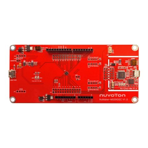
Figure 1-1 NuMaker RTU NUC980 Development Board................................................................. 5
Figure 3-1 Front View of NuMaker RTU NUC980............................................................................ 7
Figure 3-2 Rear View of NuMaker RTU NUC980.......................................................................... 11
Figure 4-1 Nuvoton USB Driver Installation Setup......................................................................... 12
Figure 4-2 Nuvoton USB Driver Installation................................................................................... 14
Figure 4-3 Hardware Setting.......................................................................................................... 15
Figure 4-4 Nuvoton VCOM............................................................................................................. 16
Figure 4-5 NuWriter Setting ........................................................................................................... 17
Figure 4-6 Program u-boot............................................................................................................. 18
Figure 4-7 Program uimage........................................................................................................... 19
Figure 4-8 Program environment................................................................................................... 20
Figure 5-1 GPIO List Schematic .................................................................................................... 21
Figure 5-2 Power Schematic.......................................................................................................... 22
Figure 5-3 NUC980DR Schematic................................................................................................. 23
Figure 5-4 Power Filter Schematic................................................................................................. 24
Figure 5-5 Configure Schematic .................................................................................................... 25
Figure 5-6 NUC123ZD4AN0 Schematic ........................................................................................ 26
Figure 5-7 Memory Schematic....................................................................................................... 27
Figure 5-8 RMII_PF connector Schematic..................................................................................... 28
Figure 5-9 RS485 and CAN Schematic ......................................................................................... 29
Figure 5-10 USB Schematic........................................................................................................... 30
Figure 5-14 Front PCB Placement................................................................................................. 31
Figure 5-15 Back PCB Placement ................................................................................................. 31
