List of Figures
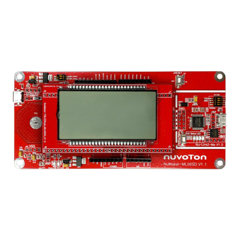
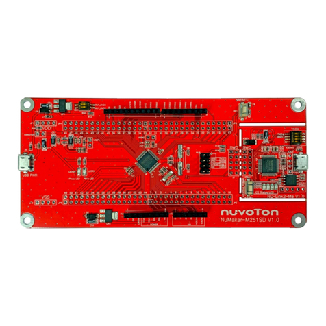
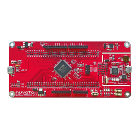
Figure 1-1 NuMaker-M252SD Board ............................................................................................... 6
Figure 2-1 Front View of NuMaker-M252SD.................................................................................... 8
Figure 2-2 Rear View of NuMaker-M252SD.................................................................................... 9
Figure 2-3 Arduino UNO Compatible Extension Connectors......................................................... 10
Figure 2-4 M252SD2AE Extension Connectors............................................................................. 12
Figure 2-5 External Power Supply Sources on Nu-Link2-Me........................................................ 17
Figure 2-6 External Power Supply Sources on M252 platform...................................................... 18
Figure 2-7 Separate the Nu-Link2-Me from NuMaker-M252SD.................................................... 19
Figure 2-8 Wiring between Ammeter Connector and Ammeter..................................................... 20
Figure 2-9 Front Placement ........................................................................................................... 23
Figure 2-10 Rear Placement.......................................................................................................... 23
Figure 3-1 Nu-Link USB Driver Installation Setup.......................................................................... 24
Figure 3-2 Nu-Link USB Driver Installation.................................................................................... 25
Figure 3-3 Open VCOM Function .................................................................................................. 26
Figure 3-4 ICE USB Connector...................................................................................................... 26
Figure 3-5 Device Manger.............................................................................................................. 27
Figure 3-6 PuTTY Session Setting................................................................................................. 27
Figure 3-7 Template Project Folder Path....................................................................................... 28
Figure 3-8 Warning Message of “Device not found” ...................................................................... 28
Figure 3-9 Project File Migrate to Version 5 Format...................................................................... 29
Figure 3-10 Debugger Setting in Options Window......................................................................... 29
Figure 3-11 Programming Setting in Options Window................................................................... 30
Figure 3-12 Compile and Download the Project............................................................................ 30
Figure 3-13 Keil MDK Debug Mode............................................................................................... 31
Figure 3-14 Debug Message on Serial Port Terminal Windows.................................................... 31
Figure 3-15 IAR EWARM Window................................................................................................. 32
Figure 3-16 Compile and Download the Project............................................................................ 32
Figure 3-17 IAR EWARM Debug Mode ......................................................................................... 33
Figure 3-18 Debug Message on Serial Port Terminal Windows.................................................... 33
Figure 4-1 Nu-Link2-Me Circuit...................................................................................................... 34
Figure 4-2 M252 platform Circuit.................................................................................................... 35
Figure 4-3 Extension Connectors Circuit ....................................................................................... 36
