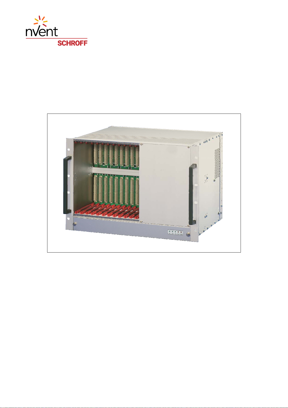
VME Subrack System 7 U
20836-715/-718
www.schroff.biz I R1.1, November 14, 2008
Table of Contents
1 Safety................................................................................................................. 1
1.1 Intended Application............................................................................................ 1
1.2 Safety Instructions............................................................................................... 2
1.3 Safety Symbols used in this document................................................................ 2
1.4 General Safety Precautions................................................................................. 2
1.5 References and Architecture Specifications........................................................ 3
2 Product Definition............................................................................................. 4
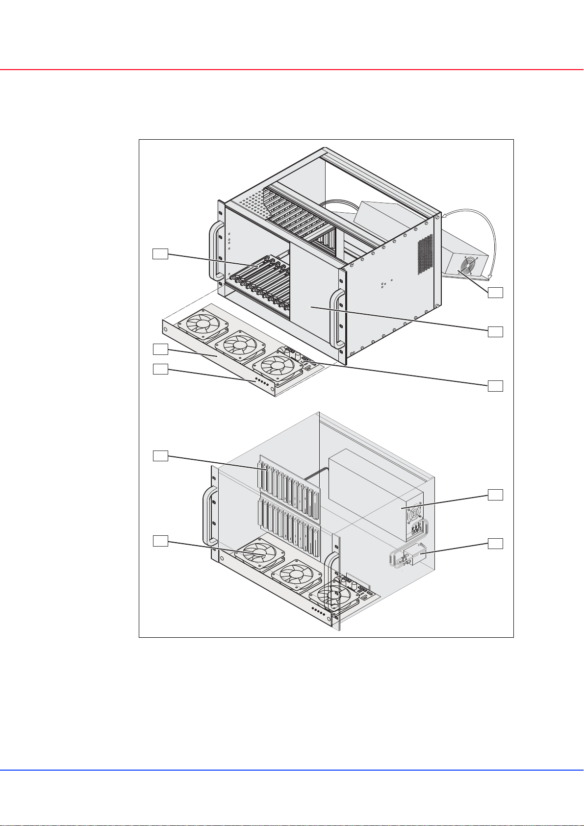
2.1 Mechanical Overview........................................................................................... 5
2.2 Subrack................................................................................................................ 6
2.3 VME Backplane................................................................................................... 6
2.4 Power Supply....................................................................................................... 7
2.4.1 Grounding.............................................................................................. 7
2.5 Thermals............................................................................................................ 10
2.6 Fan Control Module (FCM)................................................................................ 11
2.7 Chassis Monitoring Module (CMM) -optional- ................................................... 12
2.8 Display Module.................................................................................................. 13
3 Installation....................................................................................................... 14
3.1 Unpacking.......................................................................................................... 14
3.1.1 Ensuring Proper Airflow....................................................................... 14
3.2 Rack-Mounting................................................................................................... 15
3.3 Assembly of additional Backplanes................................................................... 16
3.4 Basic Functional Check..................................................................................... 17
4 Service............................................................................................................. 18
4.1 Technical support and Return for Service Assistance....................................... 18
4.2 Declaration of Conformity.................................................................................. 18
4.3 Scope of delivery............................................................................................... 19
4.4 Accessories ....................................................................................................... 19
4.5 Spare Parts........................................................................................................ 19
5 Technical Data ................................................................................................ 20
6 Mechanical Dimensions................................................................................. 21