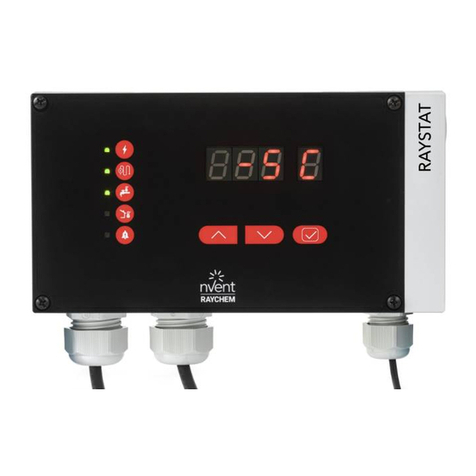
nvent RAYCHEM T2000 Installation guide

ALARM/COMMUNICATIONS
INTERFACE
T2000
CM 2000
RECEIVE
CARRIER
REQ TO SEND
ALARM
TRANSMIT
CONTROL MODULE
T2000
TEMP CURRENT SET PT
OUTPUT
ALARM
TRANSMIT
RECEIVE
11758
ADDRESS
CM 2000
˚F
CONTROL MODULE
T2000
TEMP CURRENT SET PT
OUTPUT
ALARM
TRANSMIT
RECEIVE
11758
ADDRESS
CM 2000
˚F
CONTROL MODULE
T2000
TEMP CURRENT SET PT
OUTPUT
ALARM
TRANSMIT
RECEIVE
11758
ADDRESS
CM 2000
˚F
CONTROL MODULE
T2000
TEMP CURRENT SET PT
OUTPUT
ALARM
TRANSMIT
RECEIVE
11758
ADDRESS
CM 2000
˚F
CONTROL MODULE
T2000
CONTROL MODULE
T2000
CONTROL MODULE
T2000
CONTROL MODULE
T2000
CONTROL MODULE
T2000
CM 2000 Control Module, Firmware versions up to V2.35
CM 2000+ Control Module, Firmware versions up to V3.1X
AC 2000 Alarm/Communications Interface
AC 2000+ Alarm/Communications Interface, Firmware versions up
to V1.4X
Installation, Operating, and Maintenance manual
T2000 HEAT TRACE
CONTROLLER

2 | nVent.com
CONTENTS
Introduction 4
Certication 4
General Instructions 4
Limited Warranty 4
Conducted and Radiated Emissions—FCC/DOC Statement of Compliance 4
Technical Support 4
Important Warnings and Notes 5
Section 1 Overview 6
1.1 Introduction 6
1.2 nVent RAYCHEM T2000 Components 6
1.3 External Programming Devices 8
1.4 Control Module Overview 9
1.5 AC 2000+ Card Overview 11
1.6 Component Ordering Guide 12
Section 2 Installation and Wiring 15
2.1 Introduction 15
2.2 Initial Inspection 15
2.3 Operating Environment 15
2.4 Installation Location 15
2.5 Mounting Procedures 15
2.6 Wiring 17
2.7 Initial Power Up 18
Section 3 Control Module Programming and Conguration 19
3.1 Introduction and Initial Power-Up 19
3.2 Front Panel Features 19
3.3 Displayed Alarm Indicators 21
3.4 Point Setup Parameters 24
3.5 Alarm Settings 31
Section 4 Control Module Monitored Parameter Details 39
4.1 Introduction 39
4.2 Analog Readings 39
4.3 Maintenance Data 40
Section 5 Control Module Control Modes 42
5.1 Introduction 42
5.2 Switch Control Modes 42
5.3 Load Shedding Control Mode 44
5.4 Ambient Temperature Control (ATC) Mode 45
Section 6 Control Module Troubleshooting 46
6.1 Operator Checks 46
6.2 Common Problem Areas 46
6.3 Common Alarms—What to Look For 49
Section 7 AC 2000+ Programming and Conguration 52
7.1 Introduction 52
7.2InitialConguration 52
7.3 Input/Output Ports 53
7.4OperationalConguration 55
7.5 Remote Data Access 57
7.6 AC 2000+ Alarms – What to Look For 58

nVent.com |3
Section 8 Maintenance 59
8.1 Operator Maintenance 59
8.2 Replaceable Parts 59
Appendix A Specications 60
Appendix B RAYCHEM T2000 HTC Component Wiring Diagrams 63
B.1 Control Module / CT 2000 Contactor Wiring Diagram 63
B.2 Control Module / CT 2000-HAZ Single Pole SSR Wiring Diagram 64
B.3 Control Module / CT 2000-HAZ Two Pole SSR Wiring Diagram 65
B.4 AC 2000 Alarm / Communications Interface Card Wiring Diagram 66
B.5 AC 2000+ Alarm Communications Interface Card Wiring Diagram 67
B.6 AC 2000+ Local Port RS-232 Connections 68
B.7 External Alarm and Warning Relay Connections 68
B.8 CR 2000 Card Rack Terminal Assignments 69
B.9 CR 2000 Rev. A Card Rack Terminal Assignments 70
B.10 CR 2000+ Card Rack Terminal Assignments 71
Appendix C Label Details 72
Appendix D Card Rack Dimensions 73
Appendix E Load Shedding Operations 74
E.1 AC 2000+ LOAD SHEDDING SEQUENCE 74
E.2 CONTROL MODULE LOAD SHEDDING SEQUENCE 75
Appendix F 100 W PLATINUM RTD Table 76
Appendix G Factory Default / Conguration Sheets 77
G.1CM2000ControlModuleV2.35CongurationSheet 77
G.2CM2000+ControlModuleV3.1XCongurationSheet 78

4 | nVent.com
INTRODUCTION
Installation and Maintenance Instructions for:
• CM 2000 Control Module, firmware versions up to and including V2.35
• CM 2000+ Control Module, firmware versions up to and including V3.1X
• AC 2000+ Alarm/Communications Interface, firmware versions up to and including V1.4X
Notice: The information contained in this document is subject to change without notice.
CERTIFICATION
nVent certifies that this product meets its published specifications at the time of shipment
from the factory.
GENERAL INSTRUCTIONS
nVent strongly recommends careful consideration of the following when specifying and
installing the RAYCHEM T2000 HTC. Before installing a unit, the Installation and Maintenance
instructions provided with the unit must be read and understood.
• To avoid damaging the unit, never exceed the limits stated in the literature and on the labels.
• Use a back-up unit for applications where damage to a primary unit could endanger life, limb
or property.
• A high or low limit switch is necessary for applications where dangerous runaway conditions
could result.
• Adjustable ranges must be selected so that incorrect, inadvertent or malicious setting at any
range point cannot result in an unsafe system condition.
• Install units where shock, vibration and ambient temperature fluctuations will not damage
the unit or affect operations. Orient the equipment so that moisture does not enter the
enclosure via the electrical connection.
• The unit must not be altered or modified after shipment. Consult nVent if modification is
necessary.
• Periodic testing is necessary for critical applications where damage to unit could endanger
property or personnel.
• Electrical ratings stated in literature and on labels must not be exceeded. Overload on a
switch can cause damage, possibly on the first cycle. Wire the unit according to local and
national electrical codes.
• Use only nVent authorized replacement parts and procedures.
LIMITED WARRANTY
nVent’ limited standard warranty applies to all RAYCHEM products. You can access the
complete warranty on nVent.com
CONDUCTED AND RADIATED EMISSIONS—FCC/DOC STATEMENT OF COMPLIANCE
This equipment has been tested and found to comply with the limits for a Class A digital
device, pursuant to Part 15 of the FCC rules. These limits are designed to provide reasonable
protection against harmful interference when the equipment is operated in a commercial
environment. This equipment generates, uses, and can radiate radio frequency energy and,
if not installed and used in accordance with the instruction manual, may cause harmful
interference to radio communications. Operation of this equipment in a residential area is
likely to cause harmful interference, in which case the user will be required to correct the
interference at his own expense.
This equipment does not exceed Class A limits for radio emissions as set out in Schedule V to
VIII of the Radio Interference Regulations of Communication Canada.
Cet apparel respecte les limites de bruits radioelectriques applicables aux appareils
numeriques de Classe A prescrites dans la norme sur le materiel brouilleur:
“Appareils Numeriques,” NMB-003 edictee par le Ministre des Communications.

nVent.com |5
TECHNICAL SUPPORT
Local Representatives – Contact your local nVent representative for help. For the most
up-to-date and complete listing, go to nVent.com, click Heating > Customer Support, select
your region, click Go, choose an application, enter your postal code if prompted, and click Find.
Contact information for your local representative will appear.
FAQ – For Frequently Asked Questions, go to nVent.com, click Heating > Technical Support,
and select FAQ.
IMPORTANT WARNINGS AND NOTES
The following icons are used extensively throughout this manual to alert you to important
warnings that affect safety and to important notes that affect the proper operation of
the unit. Be sure to read and follow them carefully.

6 | nVent.com
SECTION 1 OVERVIEW
1.1 INTRODUCTION
This manual provides information pertaining to the installation, operation, testing, adjustment,
and maintenance of all the components of the RAYCHEM T2000 Series Heat Tracing
Controller (HTC). A RAYCHEM T2000 HTC is made up of at least one card rack, one alarm/
communications interface card, and one or more control modules, each with its own current
transformer and switching module.
The information coincides with the specific releases of firmware for the CM 2000, CM 2000+
and the AC 2000+ components which are listed on the cover page. As nVent releases new
firmware to significantly modify or enhance any of these components, new documentation
will accompany these releases. To ensure that you are using the correct documentation
for your particular version of RAYCHEM T2000 HTC, compare the firmware version number
of each component against the version numbers listed on the front page of this manual.
Assubsequentchangesaremade,supplementstothisdocumentwillbeincludedinmanuals
shipped after the firmware is released. Supplements will make specific reference to the
operational or functional changes.
Additional copies of this manual may be downloaded from the Literature section of
nVent.com.
1.2 RAYCHEM T2000 COMPONENTS
The RAYCHEM T2000 HTC is made up of a number of modular components, allowing the
ultimate in design flexibility. Figure 1-1 shows the RAYCHEM T2000 HTC with all of its
components. Appendix A lists the specifications for all of these components.
Flexible switch and wiring configurations allow the RAYCHEM T2000 HTC to be used in most
heat tracing applications. Please contact your nearest nVent sales office to discuss your
requirements. The following sections describe the primary function of each component.
1.2.1 CM 2000 CONTROL MODULE
The CM 2000 control module is the original control module used in the RAYCHEM T2000
system and has been replaced by the CM 2000+. Firmware versions will range from versions
V2.30 to V2.35. The CM 2000 control module is designed to provide all heat tracing control and
monitoring functions for a single heating circuit. It easily inserts into any of the four types of
card racks.
1.2.2 CM 2000+ CONTROL MODULE
The CM 2000+ control module is an enhanced version of the original CM 2000 control module.
Firmware versions will range from V3.14 and higher. The CM 2000+ control module is designed
to provide all heat tracing control and monitoring functions for a single heating circuit. It is
compatible with any of the four types of card racks.
1.2.3 AC 2000 ALARM/COMMUNICATIONS INTERFACE CARD
The AC 2000 is the original alarm/communications interface card designed for use with
the RAYCHEM T2000 system. As it is purely a hardware device and does not include a
microprocessor, it contains no firmware. The AC 2000 is designed to provide a modem
communications interface between the control modules and an external programming device
(780/GCC-9000, 760/HHP-9000, or 761 PMP).
One AC 2000 can act as the communications interface for up to 40 control modules. There
are four LEDs on the front panel of the AC 2000 that indicate communication activity between
the AC 2000 and any control module. There is also a single ALARM LED on the front panel to
indicate the status of the AC 2000’s internal alarm relay. This dry contact alarm relay (0.5 A
Max. 240 VAC Max.) is for remote alarm indication. It provides both a “fail-safe” normally open
and a “fail-safe” normally closed set of contacts. These normal states are true if the AC 2000 is
powered up and no alarms are present on any of the control modules (i.e.: the ALARM LED on
the front panel of the AC 2000 is off).
The AC 2000 will only operate when inserted into the left-most slot of the card rack.
However, the alarm relay connections are not available when using the CR 2000+ or the
CR 2000-CPS+ card racks.
See Appendix B4 for details on wiring to an AC 2000 alarm/communications interface card.

nVent.com |7
1.2.4 AC 2000+ ALARM/COMMUNICATIONS INTERFACE CARD
The AC 2000+ is an enhanced version of the original AC 2000 alarm/communications interface
card. It includes a microprocessor that provides the user with many more features than the
original AC 2000. Firmware versions may range from V1.00 and up. The AC 2000+ is designed
to provide communications interfacing (using isolated 2-wire RS-485, RS-232, or 10Base-T
Ethernet) between the control modules and an external programming device that supports the
Modbus®protocol (see Section 1.3). Each communications port on the AC 2000+ has its own
RX and TX LEDs to indicate communication activity.
The AC 2000+ includes “alarm” and “warning” relay driver outputs to drive external relays
connected to local annunciators. Each output has its own LED on the front panel,
to indicate its status. The AC 2000+ must only be inserted into the left-most slot of any of
the four types of card racks. However, the alarm and warning relay driver outputs,
and some of the communication ports are not available when using the CR 2000 or
the CR 2000-CPS card racks.
See Appendices B5 to B10 for details on wiring to an AC 2000+ alarm/communications
interface card.
1.2.5 CR 2000 CARD RACK
The CR 2000 card rack was the original card rack designed for use with the RAYCHEM T2000
system. It provided each control module its own isolated power supply connection.
Two versions of this card rack have been manufactured. The first version did not support the
ATC (Ambient Temperature Control) signal connection between the ten control modules, and
the second (Rev A) version did support the ATC signal. The CR 2000 card rack is designed to
provide mechanical protection and wiring terminals for one alarm/communications interface
card and up to ten control modules. The card rack also provides wiring terminals allowing the
inter-connection of up to another three card racks.
The following are the signal connections provided by the card rack for each of the ten control
modules:
• Two RTD inputs
• One ground fault current transformer input
• One load current transformer input
• One output to control either an SSR or contactor
• Power supply input
The following are the common signal connections provided by the card rack for each of the ten
control modules:
• Communications connections with the alarm/communications interface card
• Control module alarm status signal
• ATC signal interconnection with each of the ten control modules
The following are the signal connections provided by the CR 2000 card rack for the alarm/
communications interface card:
• A 2-wire communications connection (RS-485 or modem) for a remote programming device
• Power supply input
• One normally open dry contact relay output for a remote alarm indicator
• One normally closed dry contact relay output for a remote alarm indicator
See Appendix B8 and Appendix B9 for wiring details for a CR 2000 card rack.
1.2.6 CR 2000+ CARD RACK
The CR 2000+ card rack is similar to the original CR 2000 Rev A card rack (see Section 1.2.5),
except that it has been modified to support the additional features of the AC 2000+ alarm/
communications interface card.

8 | nVent.com
The following connections are provided for the alarm/communications interface card:
• A 2-wire communications connection (RS-485 or modem) for a remote programming device
• Power supply input
• One “warning” relay driver output for driving an external relay
• One “alarm” relay driver output for driving an external relay
• A second 2-wire RS-485 communications connection for a local programming device
• An Ethernet connection
See Appendix B10 for wiring details for a CR 2000+ card rack.
1.2.7 CR 2000-CPS CARD RACK
The CR 2000-CPS card rack is similar to the original CR 2000 card rack (see Section 1.2.5),
except it is modified so that each of the ten control modules use a common power supply
connection originating at the alarm/communications interface card in the left-most slot.
1.2.8 CR 2000-CPS+ CARD RACK
The CR 2000-CPS+ card rack is similar to the CR 2000+ card rack (see Section 1.2.6), except it
is modified so that each of the ten control mod-ules use a common power supply connection
originating at the alarm/communications interface card in the left-most slot.
1.2.9 CT 2000 CURRENT TRANSFORMER AND CONTRACTOR
SWITCHING MODULE
The CT 2000 current transformer and contactor switching module is used by a control module
that implements a contactor as its output switch. The control module connects to the CT 2000
via the connections on the card rack (see Appendix B1). The CT 2000 is used to measure load
and ground fault currents using internal current transformers as well as to switch an external
contactor using an internal relay.
1.2.10 CT 2000-HAZ CURRENT TRANSFORMER MODULE
A control module that implements an SSR as its output switch uses the CT 2000-HAZ current
transformer module. The control module connects to the CT 2000-HAZ via the connections on
the card rack (see Appendix B2 and Appendix B3). The CT 2000-HAZ is used to measure load
and ground fault currents using internal current transformers. The external SSR is controlled
directly by the control module via connections on the card rack.
1.2.11 BC 2000 BLANK COVER
The BC 2000 blank cover is used to cover slots in the card rack that do not contain a control
module or an alarm/communications interface card.
1.3 EXTERNAL PROGRAMMING DEVICES
The AC 2000+, CM 2000, and CM 2000+ devices require an external programming device to
view and modify their parameters and data. The type of device depends on the type of alarm/
communications interface card being used by the RAYCHEM T2000 HTC. The following
sections give details on the programming devices that may be used with each type of alarm/
communications interface card.
1.3.1 AC 2000 PROGRAMMING DEVICES
When using an AC 2000 alarm/communications interface card, only the following
programming devices may be used to access the parameters and data of a
RAYCHEM T2000 HTC:
• 780/GCC-9000 Group Communications Controller
• 760/HHP-9000 Handheld Programmer
• 761 Panel Mount Programmer
IMPORTANT: When using the 780/GCC-9000 Group Communications Controller, all of the
programming devices mentioned in Section 1.3.2 can be used upstream from the GCC.

nVent.com |9
1.3.2 AC 2000+ PROGRAMMING DEVICES
When using an AC 2000+ alarm/communications interface card, only programming devices
that support the Modbus protocol (Personal Computer, PLC, or DCS) may be used to access
the parameters and data of a RAYCHEM T2000 HTC.
When using a personal computer, we recommend using the RAYCHEM Supervisor
Configuration and Monitoring software to manage your RAYCHEM control system. The
software allows you to configure and monitor any RAYCHEM controller installed in the field
which includes an appropriate communications interface. The software also supports alarm
monitoring, with the ability to acknowledge and clear alarms, and advanced features such as
data logging, trending, recipes and batching.
For portable solutions, use the RAYCHEM PPD-IND or PPD-HAZ Portable Programming
Devices. These Windows CE-based PDAs (Personal Digital Assistants) provide an intuitive,
graphical user interface for configuration and troubleshooting. Access to all AC2000+
parameters is available, and interface cables are included to allow easy connection to your
T2000 panel. For more information, refer to the Portable Programming Device (PPD) Software
Installation and Operating Instructions document (H57402).
1.4 CONTROL MODULE OVERVIEW
1.4.1 DESCRIPTION
The CM 2000 and the CM 2000+ control modules, used in the RAYCHEM T2000 HTC each
control, monitor, and communicate alarms and data for a single heating circuit. As single point
controllers, they offer a complete range of features as well as superior reliability. The ability
to install the units in Class 1, Division 2 hazardous areas supports direct field installation if
desired.
The option to use either an external solid-state relay (SSR) or an external contactor to switch
single phase or three wire, three phase loads up to 600 VAC, makes the CM 2000/CM 2000+
control modules the most versatile products on the market.
1.4.2 FEATURES
A detailed description of available features in the CM 2000 and the CM 2000+ control modules
may be found in Section 3 of this manual. Highlights of specific features are included in the
following text.
Digital Readout
The actual temperature, the load current and the temperature setpoint are immediately
accessible to plant operators and maintenance staff. The display units are field selectable in
°For°C.
–40 to 149°F (–40 to 65°C) Operation
Extended temperature operation permits installation in all but the harshest environments.
Single or Dual Temperature Sensor Inputs
The ability to utilize one or two temperature sensor (TS) inputs, allows the selection of one of
nine control modes and programming of all temperature parameters.
High and Low Temperature Alarms
High and low temperature alarms are offered for both temperature sensor inputs.
High and Low Current Alarms
The low current alarm is more than just a continuity level alarm. The control module offers full
adjustment of both the high and the low alarm points over the entire current measurement
range.
Solid-state Relay (SSR) or Electro-mechanical Relay (EMR) Output
The CM 2000/CM 2000+ control modules are used with the CT 2000 current/switch module
to monitor load and ground fault currents as well as drive a remote electro-mechanical relay
(EMR) output switch. The CT 2000-HAZ current module is used to monitor load and ground
fault currents when driving a solid-state relay (SSR). With the SSR option, the user may
select a time-proportional control algorithm, a simple deadband control algorithm, or one of
two ambient control algorithms. The EMR version always uses either the deadband control
algorithm or the proportional ambient contactor control algorithm. Switching device failure
alarms are supported for both types of output devices.
10 | nVent.com
Ground Fault Alarm and Trip
Ground Fault (GF) current levels are monitored and may be displayed in mA. The availability of
the actual ground fault level gives the user the choice of both alarm and trip levels suitable for
the particular installation.
Overcurrent Protection
A unique overcurrent protection algorithm greatly reduces the possibility of damage to the
heating circuit or the SSR in the event of a temporary overload while allowing for initially high
in-rush currents (SSR options only).
Soft Starting
Given the circuit breaker size, the control module will limit the energy let-through to help
prevent nuisance breaker trips due to cable in-rush. This feature makes the control module
particularly attractive for use with self-regulating cables (SSR options only).
Minimum/Maximum Temperature Tracking
The control module maintains the minimum and maximum temperature values it has
measured since the last reset of these values. This is helpful in determining causes of
temperature alarms.
Latching/Non-latching Temperature Alarms
User selectable non-latching temperature alarms allow the control module to automatically
clear the alarm when the condition no longer exists.
High and Low Voltage Alarms
Operating at voltages less than design can cause serious loss of heater output. The alarming
of preset voltage deviations ensures the availability of sufficient wattage output.
Power-Limiting
The control module will control the maximum output wattage if the full load power exceeds
the specified Maximum Power Setpoint. This feature eliminates the need for low voltage
transformers in many applications and can assist in standardization of heating cable types
(SSR options only).
Auto-cycling
The control module will momentarily energize its heating circuit (for 10 seconds) at a
programmable interval. Heating circuit alarms will be generated at the time of auto-cycle
instead of when the heat is required. This feature eliminates the need for a preventative
maintenance program as these tests are performed at regular intervals by the control module.
Temperature Sensor Failure Alarm
Both open and shorted sensors are detected and alarmed by the control module. Additionally, the
control module may be configured to default to a remaining “good” sensor or to turn the output off.
Random Start
A startup delay between 0 and 9 seconds ensures that all control modules do not come on line
at the same time following a power failure.
Full Digital Communications
All control modules can communicate alarm and analog data to a monitoring system via the
alarm/communications interface card. With the availability of the heat trace data at the user’s
fingertips, historical trending of temperatures, power consumption, or other parameters are
available for analysis and system optimization.
CSA (C/US) & FM Approved
The RAYCHEM T2000 system is approved and certified for use in Class 1, Division 2, Groups
A,B,C,D hazardous locations, making them ideal for direct installation in the field. This can save
the expense of wiring back to a centrally located electrical distribution center.
Compact Size Modules
Innovative modular packaging allows for field addition of control modules as heating circuits
are added. Individual heating circuits can easily be locked out or replaced without affecting
other heating circuits. All heating circuits can be monitored simultaneously without scrolling.
Universal Voltage Input
The control module’s wide voltage input range (90 to 240 VAC) gives the user maximum
flexibility for installation and configuration as well as reducing the inventory requirements.

nVent.com |11
1.5 AC 2000+ CARD OVERVIEW
1.5.1 DESCRIPTION
The AC 2000+ alarm/communications interface card has similar functionality to the original
AC 2000 Alarm/Communications interface card, but also combines the features of a Group
Communications Controller (such as a Model 780/GCC-9000).
The AC 2000+ is designed to automatically poll all of the installed control modules for alarm
data as well as maintain a database of their setpoints, setup parameters, alarm and analog
data. Note that all control operations are performed by the CM 2000/CM 2000+ control
modules and not by the AC 2000+.
The user may configure setpoint or setup parameters for up to (40) CM 2000 and up to (256)
CM 2000+ control modules by using any of the AC 2000+ ports. The AC 2000+ communicates
with the control modules through the backplane of the CR 2000/CR 2000+ card rack(s).
IMPORTANT: The AC 2000+ belongs to a family of Group Communications Controller
(GCC) devices. While specific to the RAYCHEM T2000 series of products, the AC 2000+ is
nonetheless a Group Communications Controller (GCC). This nomenclature will be used
through this user manual.
1.5.2 FEATURES
A detailed description of available features supported by the AC 2000+ alarm/communications
interface card may be found in Section 7 of this manual. The following descriptions highlight
specific features of the AC 2000+:
Port Configuration
All of the communications port configuration parameters of the AC 2000+ may be reviewed
or modified via the local front panel RS-232 port using a PC running the “Communication
Controller Configuration Utility” program (see Section 1.5.3).
Communication Ports
All RAYCHEM T2000 HTC parameters and data may be reviewed and modified through the
following three communication ports of the AC 2000+:
1. Remote Port: This isolated RS-485 serial port allows up to (31) AC 2000+ devices to be
multi-dropped onto the same pair of RS-485 communication wires and then connected to a
remote upstream programming device such as a host computer, PLC or DCS.
2. Local Port: This serial port may be configured to use either the front panel RS-232
interface or the 2-wire RS-485 interface on the back of a CR 2000+ card rack. Select the
RS-232 interface to connect with one Personal Computer, PLC or DCS in close proximity
totheAC2000+.SelecttheRS-485interfaceifanumberofAC2000+devicesaretobe
multi-dropped onto the same pair of communications wires and connected to a local
communications device.
3. Ethernet Port: This connection provides an industry-standard 10Base-T interface and
supports a Modbus/TCP connection. This port is typically used when remote monitoring and
configuration is required using an Ethernet Local Area Network (LAN).
Relay Driver Outputs
The AC 2000+ has two “fail-safe” outputs to drive external 12Vdc relay coils. One is used for
indicating “Alarm” conditions and the other for indicating “Warning” conditions.
Monitoring
The status of the AC 2000+, and all of the control modules are continuously monitored for
proper operation and various alarm conditions. Control module information includes discrete
setpoint, setup and alarm data, as well as analog values such as temperatures, currents, etc.
Tags
The AC 2000+ and each control module may be assigned an identification tag eliminating
confusing codes or cross-referencing. Tags may be up to 19 alpha-numeric characters in length.
Load Shedding
This is an advanced control mode, managed by the AC 2000+ alarm/communications interface
card. Load shedding overrides temperature control and forces the output of the selected
control modules off until reset by the AC 2000+. This mode is initiated by using a remote
Modbus command from an external upstream programming device. See Sections 3.4.18
to 3.4.20, 5.3, 7.4.2, 7.4.3, 7.4.6.7, and 7.4.7 as well as Appendix E in this manual for details
regarding the load shedding features and related parameters.

12 | nVent.com
1.5.3 ADDITIONAL DOCUMENTATION
In addition to this manual, details of the Modbus protocol mapping for the AC 2000+ may be
found in the Group Communications Controller: Modbus Protocol Interface – Linear Mapping
and the Group Communications Controller: Modbus Protocol Interface – Page Mapping
documents. This information will be required to properly communicate with and operate the
AC 2000+ using a remote personal computer, process computer, or some other form of host
computer system.
The Communication Controller Configuration Utility, Installation and Operating Instructions
document will provide information on how to set up various communication parameters
required by the AC 2000+ alarm/communications interface card using the “Communication
Controller Con-figuration Utility” program.
1.5.4 SUPPORT
Application assistance is available from nVent for questions specific to the operation of the AC
2000+ hardware and software or its use in conjunction with the CM 2000 and the CM 2000+
control modules.
1.6 COMPONENT ORDERING GUIDE
The T2000 system consists of the following components:
• CR 2000+ Card Rack (can accommodate one AC 2000+ and p to 10 CM 2000+’s)
• AC 2000+ Alarm/Communications Interface
• CM 2000+ Control Module
• CT 2000 CT Module
• Switching Device (Solid-state Relay or contactor)
Figure 1.1 RAYCHEM T2000 System Components

nVent.com |13
The following tables summarize model codes for the RAYCHEM T2000 series products. Note
that the first table identifies the most recent products. These components should be specified
for new designs.
Current Product Model Codes
Model Code Model Description Detailed Description
CM 2000+ RAYCHEM T2000 Control
Module with advanced
feature set
Plug-in control module, with firmware
versions V3.14 and up, that provides all heat
tracing control and monitoring functions.
Plugs into all types of CR 2000 card racks and
interfaces with all types of CT 2000 and AC
2000 modules.
AC 2000+ Alarm/Communications
Inter-face Card with GCC
functionality
Plug-in modules that provides RS-232, RS-485
or Ethernet interfacing between CM 2000/
CM 2000+ control modules and a PC or an
external upstream programming device.
Includes two relay output devices for remote
alarm and warn-ing indication.
CR 2000+ Isolated Power Card Rack
supporting AC 2000+
features
Panel mount rack provides mechanical
protection and electrical connections for the
CM 2000/CM 2000+ control modules as well
as the AC 2000+ module. All control modules
are individually powered.
CR 2000-
CPS+
Card Rack with Common
Power Supply supporting AC
2000+ features
Panel mount rack provides mechanical
protection and electrical connections for the
CM 2000/CM 2000+ control modules as well
as the AC 2000+ module. All control modules
utilize a common power source.
CT 2000 CT module for use with
Electromechanical
Contractors
Current transformer and switching module.
Load current conductors pass through to
provide accurate load current and ground
fault current measurements. Internal relay
switches an exter-nal contactor. Interfaces
with the CM 2000/CM 2000+ control
modules.
CT 2000-HAZ CT Module for use with
Solidstate Relay Modules
Approved For Hazardous
Areas
Current transformer module. Load current
conductors pass through this module to
provide accurate load current and ground
fault measurements. Internal circuitry drives
an external solid-state relay. Interfaces with
the CM 2000/CM 2000+ control modules.
BC 2000 Blank Cover Blank cover plate to occupy empty or unused
slots in all types of CR 2000 card racks.

14 | nVent.com
Legacy Product Model Codes
Model Code Model Description Detailed Description
CM 2000 TRACER™ 2000 Control
Module
Plug-in control module that provides all heat
tracing control and monitoring functions.
Plugs into all types of CR 2000 card racks
and interfac-es with CT 2000 and AC 2000
modules. Use a CM 2000+ for new designs.
AC 2000 Alarm/
Communications
interface Card
Plug-in module that provides a modem
interface between CM 2000/CM 2000+ control
modules and an external 780 Series/GCC-
9000, 760 Series/HHP-9000, or 761 Series
programmer. Includes a relay for remote alarm
indication.
CR 2000 Isolated Power Card
Rack
Panel mount rack provides a mechanical
protec-tion and electrical connections for the
CM 2000/CM 2000+ control modules and
the AC 2000 module. All control modules are
individually powered. Use a CR 2000+ for new
designs.
CR 2000-CPS Card Rack with
Common Power
Supply
Panel mount rack provides a mechanical
protec-tion and electrical connections for the
CM 2000/CM 2000+ control modules and
the AC 2000 module. All control modules are
individually powered. Use a CR 2000-CPS+ for
new designs.

nVent.com |15
SECTION 2 INSTALLATION AND WIRING
WARNING:
Electrical Hazard
Ensure all personnel involved in installation, servicing, and programming are qualified and
familiar with electrical equipment, their ratings and proper practices and codes. Multiple
voltages and signal levels may be present during the installation, operation, and servicing of
this product. Do not power the product until the safety provisions outlined in this section have
been observed.
2.1 INTRODUCTION
This section includes information regarding the initial inspection, preparation for use, and
wiring instructions for the components of the RAYCHEM T2000 HTC. See Appendix B for wiring
details.
2.2 INITIAL INSPECTION
Inspect the shipping container for damage. If the shipping container or cushioning material
is damaged, it should be kept until the contents of the shipment have been verified for
completeness and the equipment has been checked mechanically and electrically. Procedures
forconfiguringandoperatingtheRAYCHEMT2000HTCaregiveninSections3and7.Ifthe
shipment is incomplete, mechanically damaged, defective in any way, or the RAYCHEM
T2000HTCdoesnotpasstheelectricalperformancetests,notifythenearestnVent
representative. If the shipping container is damaged, or the cushioning material shows signs of
stress,notifythecarrieraswellasyournVentrepresentative.Keeptheshippingmaterialsfor
the carrier’s inspection.
2.3 OPERATING ENVIRONMENT
The standard CM 2000/CM 2000+ control module using a Solid-state Relay (SSR) and a
CT2000-HAZmodule,issuitableforClass1,Division2,GroupsA,B,CandDhazardousareas.
Hazardous areas are defined by Article 500 of the National Electrical Code and Section 18 of
the Canadian Electrical Code.
The standard CM 2000/CM 2000+ control module using an Electro-mechanical contactor and
a CT 2000 module is suitable for use in ordinary (non-hazardous) areas only.
WARNING:
Some wiring configurations will use more than one power source and all must be de-energized
prior to performing any maintenance on a control module or its heating circuit.
The operating environment should be within the limitations specified for the RAYCHEM
T2000HTCcomponentsasoutlinedinAppendixA.
2.4 INSTALLATION LOCATION
The wide ambient operating temperature range of the RAYCHEM T2000 HTC permits
installation in most any convenient location. Considerations should include expected
atmospheric conditions, accessibility for maintenance and testing, the location of existing
conduits, and hazardous area rating. Ambient temperature conditions may affect load
current ratings.
WARNING:
Fire and Explosion Hazard
Be sure the product is approved for the intended location as defined by Article 500 of the
National Electrical Code and/or Part I, Section 18 of the Canadian Electrical Code.
2.5 MOUNTING PROCEDURES
2.5.1 CARD RACK REMOVAL AND INSTALLATION
WARNING:
Shock Hazard
Turn off all power to the card rack and individual control modules during installation or removal
to avoid the risk of injury to personnel and damage to the RAYCHEM T2000 HTC.

16 | nVent.com
WARNING:
Electrical Hazard
Always verify all wiring connections before applying power to the card rack or any heating
circuit. To avoid injury or equipment damage, do not install or remove wiring while power is on.
Both types of CR 2000 and CR 2000+ card racks are designed to be mounted to a swing out
door of a panel using four card rack mounting brackets (see Appendix D for panel cutout and
dimensions). Remove all wires connected to the terminal blocks on the back of the card rack
by inserting a small bladed screw driver in the terminal block slot and pulling the wires out
of the terminal block. Pay particular attention to the location of each wire, as all wires must
be terminated properly upon replacement for proper operation. Incorrect terminations may
damage a control module or the alarm/communications interface card.
To remove the card rack from the panel, loosen the mounting screw on each of the four
mounting brackets located on both the top and bottom sides of the card rack. Once loose, the
mounting bracket may be removed from the card rack by sliding it forward and lifting vertically
from the card rack.
Install in the reverse order.
2.5.2 CONTROL MODULE REMOVAL AND INSTALLATION
WARNING:
Shock Hazard
Always ensure that all power to the individual control modules is turned off during installation
or removal to avoid the risk of injury to personnel and damage to the control modules.
WARNING:
Hazardous Area Explosion Hazard
Do not install or remove the control module while the unit is powered.
To remove a control module from any of the ten right-most slots of the card rack, loosen the
screw on the top front edge of the control module faceplate. However, do not remove it! Once
the screw has been loosened approximately 1/4”, grasp the screw and pull firmly straight
out, away from the card rack. If the screw is still engaged, slowly loosen it by hand continuing
to pull away from the card rack. When the mounting screw is free of the card rack, slide the
control module out of the card rack by grasping the faceplate. Do not handle the control
module by the PC board. Store immediately in the anti-static bag provided.
Install in the reverse order.
2.5.3 ALARM/COMMUNICATION INTERFACE CARD REMOVAL AND INSTALLATION
WARNING:
Always ensure that all power to the alarm/communications interface card is turned off during
installation or removal to avoid the risk of injury to personnel and damage to the card.
WARNING:
Hazardous Area Explosion Hazard
Do not install or remove the alarm/communications interface card while the unit is powered.
To remove an Alarm/communications Interface card from the left-most slot of the card rack,
loosen the screw on the top front edge of the card’s faceplate. However, do not remove it!
Once the screw has been loosened approximately 1/4”, grasp the screw and pull firmly straight
out, away from the card rack. If the screw is still engaged, slowly loosen it by hand continuing
to pull away from the card rack. When the mounting screw is free of the card rack, slide the
interface card out of the card rack by grasping the faceplate. Do not handle the interface card
by the PC board. Store immediately in the anti-static bag provided.
Install in the reverse order.
IMPORTANT:
• When using an AC 2000 with a CR 2000+ or a CR 2000-CPS+ card rack, the dry contact alarm
relay connections are not available.

nVent.com |17
• When using an AC 2000+ with a CR 2000 or a CR 2000-CPS card rack, the alarm and warning
relay driver outputs, the Ethernet communication port, and the Local RS-485 communication
port are not available.
2.5.4 CT MODULE REMOVAL AND INSTALLATION
WARNING:
Always ensure that all power to the individual heating circuit is turned off during installation or
removal to avoid the risk of injury to personnel and damage to the CT module.
WARNING:
Hazardous Area Explosion Hazard
Do not install or remove the CT module while the unit is powered.
To remove a CT module, first remove the wires that pass through the CT module from the
contactor, SSR, or the field wiring terminals and carefully pull the wires through the CT module
housing. Next remove all of the wires from the CT module terminal block by inserting a small
bladed screw driver in the terminal block slot and pulling the wire out of the terminal block.
Remove the two mounting screws and remove the CT module.
Install in the reverse order.
2.6 WIRING
Wire the card rack as indicated by the wiring diagrams supplied. See Appendix B for a
complete set of wiring diagrams. All terminals are labeled with terminal numbers and the
corresponding legend is printed on the wiring label beside the terminal block.
Do not to use wire sizes that exceed the marked terminal ratings and avoid terminating two
wires on the same terminal.
Use of the incorrect screwdriver size may damage the terminals.
Use the terminal block behind the right-most slot, to connect the following three termination
resistors:
• 3300ΩresistoracrosstheterminalslabeledSIG+andSIG–
• 120ΩresistoracrosstheterminalslabeledTX/RX+andTX/RX–
• 120ΩresistoracrosstheterminalslabeledRTS/DCD+andRTS/DCD–
• 120ΩresistoracrosstheterminalslabeledREMOTE+andREMOTE–(AC2000+only)
• 120ΩresistoracrosstheterminalslabeledLOCAL+andLOCAL–(AC2000+only)
Use twisted, three-conductor shielded cable for extending RTD leads. Wire size should ensure
that the maximum lead resistance specified for the CM 2000/CM 2000+ is not exceeded.
Communications wiring should be two conductor twisted shielded cable. Shields on both
RTD and communications wiring should be grounded at one end only. Communications cable
shield should only be grounded at the alarm/communications interface card terminal provided.
RTDcableshieldsshouldbegroundedatthecontrolmoduleterminalprovided.
If the card racks are installed in either a metallic or non-metallic enclosure, follow the
enclosure manufacturer’s recommendations for proper grounding. Do not rely on conduit
connections to provide a suitable ground.
A ground terminal is provided on each card rack for connection of a system ground lead.
Proper system grounding is required for safe and correct operation of the RAYCHEM T2000
HTC protection features. Refer to Article 501-4(b) of the National Electrical Code for grounding
in hazardous areas, if appropriate.
2.6.1 ISOLATED POWER SUPPLY CARD RACK (CR 2000 & CR 2000+)
Conductors used to power the individual control modules and the alarm/communication
interface card, CT module signals, sensor inputs, alarm circuits and controller communications
all terminate on the back of the card rack. The standard card rack assembly has an individual
power source for each control module, therefore more than one power source will be present
on the card rack terminal blocks (see Appendix B).
2.6.2 COMMON POWER SUPPLY CARD RACK (CR 2000-CPS & CR 2000-CPS+)
Conductors used to power the individual control modules and the alarm/communication
interface card, CT module signals, sensor inputs, alarm circuits and controller communications
all terminate on the back of the card rack. The CPS card rack assembly has a common power

18 | nVent.com
source for all control modules. Power supply connections are made on the left-most slot
(seeAppendixBforwiringdetails).
2.6.3 CT MODULE (CT 2000 & CT 2000-HAZ)
Electrical conductors for the heat tracing load pass through the CT module housing and do not
terminate at the CT module. CT signal wires terminate on the CT module terminal block located
on the top of the CT module.
For the CT 2000 module, the contactor coil control wires terminate on the CT module terminal
block located on the top of the CT module. Switch control and CT signals must be terminated
as shown in the wiring diagrams in Appendices B-1 to B-3
WARNING:
Be certain that power has been removed from the heating circuit and control module prior to
disconnecting the switch control or CT signal leads.
2.6.4 INTERCONNECTING MULTIPLE CARD RACKS
When using an AC 2000 alarm/communication interface card, up to 4 card racks (containing
a maximum of (40) CM 2000 or CM 2000+ control modules) may be daisy-chained together to
one AC 2000.
When using an AC 2000+ alarm/communication interface card, up to (26) card racks
(containing a maximum of (256) CM 2000+ control modules) may be daisy-chained together to
one AC 2000+.
IMPORTANT: The AC 2000+ may be used with CM 2000 modules, however a maximum of
4cardracks(40CM2000s)maybedaisy-chainedtogether.
When sharing a single alarm/communications interface card among multiple card racks, it is
always inserted in the left-most slot of the first card rack. The left-most slots of the remaining
card racks are left empty.
Each card rack has two terminal blocks on the back at either side, which allows for convenient
daisy-chaining of card racks. When daisy-chaining card racks, use twisted multi-conductor
shielded cable with the shield terminated on the terminal block provided at the previous
card rack. The termination resistors are only required on the last card rack in the chain.
SeeAppendicesB4andB5forwiringdetails.
2.7 INITIAL POWER-UP
WARNING:
Before applying power to the RAYCHEM T2000 HTC:
• Close the panel door or stand clear of the RAYCHEM T2000 HTC. Although the control
modules incorporate overcurrent protection, a destructive switch failure can result from a
short circuited output. To avoid the possibility of any injury, no one should be directly in front
of the switches when they are initially powered up.
• Ensure that applying power to any heating circuit will not damage it if power limiting or the
setpoint temperature have not been set correctly. If there is any doubt, the load should be
disconnected until the control module has been suitably programmed for correct and safe
operation.
To minimize the risk of damage to the control module and its components due to a cable fault,
the integrity of the heating cable should be verified. This can be accomplished by performing
a high voltage insulation test using a “Megger” following the heating cable manufacturer’s
instructions. Ensure that the heating cable is not shorted by measuring the resistance using an
ohmmeter.
These tests must be performed with the heating cable completely disconnected.
Once the heating cable has been checked, it may be reconnected and power applied.

nVent.com |19
SECTION 3 CONTROL MODULE PROGRAMMING AND CONFIGURATION
3.1 INTRODUCTION AND INITIAL POWER-UP
Section 3 provides complete operating and programming details for the CM 2000 and the
CM 2000+ control modules. These details consist of initial power-up information, front panel
features, and function descriptions including: purpose, valid range settings, the procedure for
use, and some operational tips and suggestions.
3.1.1 RANDOM START-UP DELAY
All CM 2000 and CM 2000+ control modules incorporate a random start-up delay feature,
ensuring that all units do not power on their load the same time. When power is first applied to
a control module, it will hold its output off for a random time (0 to 9 seconds), equal to the last
digit of the address displayed on the front panel of the control module. Once this start-up delay
has timed out, the control module will begin normal operation.
3.1.2 POWER-UP OUTPUT ENABLING
When power is applied to a CM 2000 control module it will always turn its output on for approx.
6 seconds if the load shedding mode is disabled. When power is applied to a CM 2000+ control
module it will only turn its output on for approx. 10 seconds if the auto-cycling feature has
been enabled and if the control module is not in load shedding mode. By momentarily turning
the control module’s output on at power-up, the integrity of the heating circuit is tested and any
faults will be detected immediately.
3.1.3 AUTO COMMUNICATIONS DATA RATE SELECTION (CM 2000+ ONLY)
All CM 2000+ control modules will support either low or high speed data communications
to allow their use in either existing (low speed) systems or new (high speed) installations.
TheCM2000+willautomaticallysetitscommunicationsdataratetoeither300or9600baud.
This selection is based on the data rate of the first l communication detected by the CM 2000+
after it is reset. All control modules sharing a common communication bus must communicate
at the same data rate. To disable this feature, install the E6 jumper on the CM 2000+ module.
By doing this, the CM 2000+ will only communicate at 300 baud.
3.2 FRONT PANEL FEATURES
Front panel features of the control module are described in Figure 3-1. This figure contains
a detailed description of the indicators and label information. The remainder of this section
describes in detail the front panel display and status LEDs.
3.2.1 CONTROL MODULE FRONT PANEL DISPLAY
The three-character (seven segment plus decimal LED) display is found near the top of
the front panel of the CM 2000/CM 2000+ control modules. It is used to indicate certain
quantitative values to the operator. This display shows measured temperature and setpoint
values in °F or °C as well as actual load current in amperes. When the three-character display is
displaying a temperature value, either the °F LED or °C LED on right hand side of the display will
be illuminated depending on temperature units selected by the operator. Also, when displaying
temperature values in °F, the decimal point for the right-most character will also be illuminated.
3.2.2 DISPLAY OPERATION
All CM 2000 and CM 2000+ control modules have a random start-up delay associated with
them as described in Section 3.1.1. When power is first applied to a control module, it will
display the start-up delay (in seconds) and count down to zero. Immediately after this count
down has completed, the control module briefly (approximately 1/10 of a second in duration)
displays the version number of its operational program (firmware). This allows the user to refer
to specific Sections of the documentation as they relate to functions for a particular version of
the control module.
The control module then turns on all LEDs (except TRANSMIT and RECEIVE LEDs for the
CM 2000) and sequences through a test pattern so that the operator can verify that all LEDs
and display segments are functioning.

20 | nVent.com
The control module will then begin to display the following three parameters in sequence:
• Actual measured temperature from the temperature sensor(s),
• Heat trace load current in amperes, and
• The CONTROL SETPOINT temperature.
As these three values are displayed (each for approximately 2.5 seconds in duration), a
corresponding LED immediately below the display area illuminates to indicate which parameter
is being shown. Under certain conditions, the control module will display several messages on
the three-character display in place of one of these three parameters (see Section 3.3).
3.2.3 ‘TEMP’ STATUS LED
The TEMP status LED is located below the left-most character of the control module’s front
panel display. When illuminated, this LED indicates that the present value being shown on the
display is the actual temperature of the designated control temperature sensor (as determined
by the TS CONTROL MODE setting).
3.2.4 ‘CURRENT’ STATUS LED
The CURRENT status LED is located below the middle character of the control module’s front
panel display. When illuminated, this LED indicates that the present value being shown on the
display is the actual heat trace load current in amperes. If this LED is flashing, then it indicates
that the control module has measured a ground fault current in excess of the GF TRIP
CURRENT or has encountered a severe overcurrent situation and has tripped the output off.
3.2.5 ‘SETPT’ STATUS LED
The SETPT status LED is located below the right-most character of the control module’s front
panel display. When illuminated, this LED indicates that the present value being shown on the
display is the present value of the CONTROL SETPOINT temperature setting.
3.2.6 ‘OUTPUT’ STATUS LED
The OUTPUT status LED is located below the SETPT status LED on the right side of the control
module’s front panel display. When illuminated steadily, this LED indicates that the output
switch (contactor or SSR) is on and is allowing current to flow into the heating circuit. If this
LED is flashing, it indicates that the control module is pulsing its output on and off to maintain
the CONTROL SETPOINT temperature and/or control the average amount of current/power
that the heating load uses (proportional control mode, SSR option only).
3.2.7 ‘ALARM’ STATUS LED
The ALARM status LED is located below the OUTPUT status LED on the right side of the
control module’s front panel display. The color of this LED is amber for the CM 2000+, and red
for the CM 2000. If the control module detects any alarm condition, this LED will flash at a rate
of once per second.
3.2.8 ‘TRANSMIT’ STATUS LED
The TRANSMIT status LED is located below the ALARM status LED on the right side of the
control module’s front panel display. This LED will flash whenever the control module sends
information over its communication port to either the AC 2000 or the AC 2000+ alarm/
communications interface card.
3.2.9 ‘RECEIVE’ STATUS LED
The RECEIVE status LED is located below the TRANSMIT status LED on the right side of the
control module’s front panel display. This LED will flash whenever the control module receives
information over its communication port from either the AC 2000 or the AC 2000+ alarm/
communications interface card.
Table of contents
Other nvent Controllers manuals

nvent
nvent JBS-100-EC User manual

nvent
nvent RAYCHEM HWAT-ECO-16 User manual

nvent
nvent RAYCHEM ECW-GF User manual

nvent
nvent RAYCHEM Elexant 4010i User manual

nvent
nvent 910 Series Assembly instructions

nvent
nvent raychem tcontrol-cont-03 Specification sheet

nvent
nvent RAYCHEM HWAT-ECO User manual

nvent
nvent RAYCHEM Raystat V5 User manual
Popular Controllers manuals by other brands

Alemlube
Alemlube DK50 Owner technical manual

Woodward
Woodward easYgen-1600 Operation manual

DERUN LIGHTING TECHNOLOGY
DERUN LIGHTING TECHNOLOGY DR-CON-IR20M-3CH-LV user manual

MKS
MKS Oriel Instruments 3502 user manual

PCB Piezotronics
PCB Piezotronics 482B06 Installation and operating manual

Hadex
Hadex MPPT Series user manual