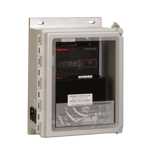
nvent RAYCHEM Elexant 4010i User manual

RAYCHEM-AR-H60624-40X0iOpsManual-EN-1905 nVent.com
|
1
nVent RAYCHEM Elexant 4010i/4020i User Manual

nVent RAYCHEM Elexant 4010i/4020i User Manual
RAYCHEM-AR-H60624-40X0iOpsManual-EN-1905 nVent.com
|
2
CONTENTS
1 OVERVIEW................................................................................................................................................................................6
1.1 Introduction ...................................................................................................................................................................6
1.1.1 Product Overview................................................................................................................................................6
1.1.2 Product Features ................................................................................................................................................7
1.2 Vital Information ..........................................................................................................................................................8
1.3 Technical Support........................................................................................................................................................8
2INSTALLATION AND WIRING ...........................................................................................................................................9
2.1 Initial Inspection...........................................................................................................................................................9
2.2 Operator Safety Considerations...............................................................................................................................9
2.3 Elexant 4010i/4020i Assembly.................................................................................................................................9
2.4 Connection and Indicators.......................................................................................................................................10
2.5 Mounting/Removal Procedures..............................................................................................................................10
2.5.1 Elexant 4010i mounting/removal procedure...............................................................................................10
2.5.2 Elexant 4020i mounting/removal procedure...............................................................................................10
2.6 Wiring and Interfaces................................................................................................................................................11
2.6.1 Input Power........................................................................................................................................................11
2.6.2 Load Connections:............................................................................................................................................11
2.6.3 AC Voltage Sense .............................................................................................................................................12
2.6.4 RS-485 IN ...........................................................................................................................................................12
2.6.5 RS-485 OUT........................................................................................................................................................13
2.6.6 Ethernet ..............................................................................................................................................................14
2.6.7 ...............................................................................................................................................................14
2.6.8 USB Connector..................................................................................................................................................14
2.6.9 Reset Button ......................................................................................................................................................15
2.6.10 3-Wire RTD Connections .................................................................................................................................15
2.6.11 2-Wire RTD Connections .................................................................................................................................15
2.6.12 4-20 mA Connections ......................................................................................................................................16
2.6.13 Connections to SSRs .......................................................................................................................................17
2.6.14 Alarm Relay........................................................................................................................................................19
2.6.15 Digital Inputs......................................................................................................................................................19
2.6.16 AUX 24V Output ................................................................................................................................................20
2.6.17 Limiter Relay Output.........................................................................................................................................20
2.6.18 Contactor Output ..............................................................................................................................................21
3PRODUCT OPERATIONS.....................................................................................................................................................22
3.1 Control Features.........................................................................................................................................................22
3.1.1 Output Type........................................................................................................................................................22
3.1.2 Control Mode Algorithms................................................................................................................................22
3.1.3 Output Overrides...............................................................................................................................................23

nVent RAYCHEM Elexant 4010i/4020i User Manual
RAYCHEM-AR-H60624-40X0iOpsManual-EN-1905 nVent.com
|
3
3.2 Monitoring ...................................................................................................................................................................26
3.2.1 Temperature ......................................................................................................................................................26
3.2.2 Electrical .............................................................................................................................................................28
3.2.3 Device Maintenance.........................................................................................................................................30
3.2.4 External Devices................................................................................................................................................31
3.3 Communication ..........................................................................................................................................................31
3.3.1 ...............................................................................................................................................................31
3.3.2 ............................................................................................................................................32
3.4 Device Information ....................................................................................................................................................33
3.4.1 Information ........................................................................................................................................................33
3.5 Alarms...........................................................................................................................................................................33
3.5.1 Alarm Relay Modes ..........................................................................................................................................33
3.5.2 Alarm Functionality ..........................................................................................................................................33
3.5.3 Alarm Sources...................................................................................................................................................34
3.6 Proles .........................................................................................................................................................................35
3.7 Internal Memory.........................................................................................................................................................35
3.8 Graphical User Interface (GUI)................................................................................................................................36
3.9 LED Status Indicators................................................................................................................................................36
3.10 GUI Screen Saver Mode............................................................................................................................................36
4 SAFETY LIMITER..................................................................................................................................................................37
4.1 Safety Limiter..............................................................................................................................................................37
4.1.1 Safety Function of the Limiter in the Elexant 4020i ...................................................................................37
4.1.2 Area of Use.........................................................................................................................................................37
4.1.3 Block Diagram ...................................................................................................................................................37
4.1.4 Resetting the Safety Limiter ...........................................................................................................................38
4.1.5 Setting the Temperature Set Point ................................................................................................................38
4.1.6 Main Output Interlock ......................................................................................................................................39
4.1.7 Internal Diagnostic............................................................................................................................................39
4.1.8 Functional Test..................................................................................................................................................39
4.1.9 Functional Test Procedure..............................................................................................................................39
4.1.10 Test in the Event of a Fault..............................................................................................................................40
4.1.11 Determining Safety Integrity of the nVent RAYCHEM Elexant 4020i-Mod-Is-Lim................................40
4.1.12 PFDavg Safety Function..................................................................................................................................40
4.1.13 System Failure Modes.....................................................................................................................................41
4.1.14 Response to Fault Conditions........................................................................................................................41
5 GRAPHICAL USER INTERFACE .........................................................................................................................................42
5.1 Home Screen...............................................................................................................................................................42
5.1.1 Control Setup.....................................................................................................................................................42
5.1.2 Temperature ......................................................................................................................................................42
5.1.3 Electrical .............................................................................................................................................................43
5.1.4 Alarms.................................................................................................................................................................43
5.1.5 Maintenance......................................................................................................................................................43
5.1.6 ................................................................................................................................................................43
5.1.7 Network ..............................................................................................................................................................44

5.1.8 Safety Limiter.....................................................................................................................................................44


nVent RAYCHEM Elexant 4010i/4020i User Manual
RAYCHEM-AR-H60624-40X0iOpsManual-EN-1905 nVent.com
|
4
5.1.9 User Interface ....................................................................................................................................................44

5.1.10 Info.......................................................................................................................................................................44

5.2 Main Screen.................................................................................................................................................................45
5.2.1 Main Screen: Single Phase Controllers.........................................................................................................45
5.2.2 Alarm Status......................................................................................................................................................46
5.2.3 Trace Status.......................................................................................................................................................46
5.2.4 Main Screen: Three-phase Controller............................................................................................................47
5.3 Information Screen.........................................................................................................................47
5.4 Control Setup ..............................................................................................................................................................48
5.4.1 Control Temp Setpoint.....................................................................................................................................48
5.4.2 Control Temp Aggregation Mode ..................................................................................................................49
5.4.3 Temperature Failure Mode..............................................................................................................................50
5.4.4 Control Temperature Alarms..........................................................................................................................51
5.5 Control Mode Page....................................................................................................................................................52
5.5.1 Control Mode.....................................................................................................................................................53
5.5.2 Algorithm Settings............................................................................................................................................54
5.5.3 Output Type........................................................................................................................................................55
5.5.4 ........................................................................................................................................56
5.6 Output Limiting Page ................................................................................................................................................57
5.6.1 Output Limiting Mode ......................................................................................................................................57
5.6.2 ..................................................................................................................58
5.6.3 Circuit Breaker Limiting ...................................................................................................................................59
5.6.4 Turns Ratio Dependent Settings....................................................................................................................60
5.6.5 Load Shedding Page ........................................................................................................................................61
5.6.6 Load Shedding Failsafe Mode........................................................................................................................62
5.6.7 Miscellaneous Page .........................................................................................................................................62
5.7 Temperature Settings Page.....................................................................................................................................65
5.7.1 ................................................................................................................................65
5.7.2 Temp Limiting....................................................................................................................................................68
5.8 Electrical Settings......................................................................................................................................................70
5.8.1 Trace Current.....................................................................................................................................................70
5.8.2 Ground Fault ......................................................................................................................................................72
5.8.3 Trace Voltage.....................................................................................................................................................73
5.8.4 Trace Resistance ..............................................................................................................................................76
5.9 Alarms...........................................................................................................................................................................77
5.10 Maintenance Page.....................................................................................................................................................79
5.10.1 Temperature ......................................................................................................................................................79
5.10.2 Volts and Power................................................................................................................................................80
5.10.3 Current ................................................................................................................................................................80
5.10.4 Misc.....................................................................................................................................................................81
5.11 Proles Page...............................................................................................................................................................83
5.12 Network Setup Page..................................................................................................................................................84
5.12.1 ...............................................................................................................................................................85
5.12.2 RS-485.................................................................................................................................................................85

nVent RAYCHEM Elexant 4010i/4020i User Manual
RAYCHEM-AR-H60624-40X0iOpsManual-EN-1905 nVent.com
|
5
5.12.3 Ethernet ..............................................................................................................................................................85
5.12.4 ............................................................................................................................................86
5.13 Safety Limiter Settings Page ..................................................................................................................................86
5.13.1 Safety Limiter Setup.........................................................................................................................................87
5.13.2 Safety Limiter Maintenance............................................................................................................................88
5.14 User Interface Settings.............................................................................................................................................90
5.14.1 Language............................................................................................................................................................90
5.14.2 Temperature Units............................................................................................................................................90
5.14.3 Passcode............................................................................................................................................................91
5.14.4 ..............................................................................................................................................................91
6 FIRMWARE UPGRADE.......................................................................................................................................................93
6.1 Firmware Upgrade Procedure..........................................................................................................93
7 TROUBLESHOOTING ...........................................................................................................................................................94
7.1 Troubleshooting .............................................................................................................................94
8 APPENDIX A ..........................................................................................................................................................................95

nVent RAYCHEM Elexant 4010i/4020i User Manual
RAYCHEM-AR-H60624-40X0iOpsManual-EN-1905 nVent.com
|
6
LIST OF TABLES
Table Page
.....................................................................................................................................6
.....................................................................................................................................7
....................................................................................................................................23
.............................................................................................................23
............................................................................................................................................24
..................................................................................................................28
................................................................................................................................................32
............................................................................................................................................32
................................................................................................................................................35
.................................................................................................................................36
.............................................................................................................................................39
..........................................................................................................40
....................................................................................................................................41
................................................................................................................................................41
.....................................................................................................................................46
.....................................................................................................................................................50
.....................................................................................................................52
..............................................................................................................................................53
.......................................................................................................................................55
...................................................................................................................................................55
.................................................................................................57
......................................................................................................................68
..............................................................................................................69
.................................................................................................71
...................................................................................................73
.................................................................................................74
.................................................................................................................................75
...........................................................................................77
.........................................................................................................77
............................................................................................................................................85
..........................................................................................................................................85
..........................................................................................................................................86
..........................................................................................................................................94
..................................................................................................................................95
...............................................................................................................................97

nVent RAYCHEM Elexant 4010i/4020i User Manual
RAYCHEM-AR-H60624-40X0iOpsManual-EN-1905 nVent.com
|
7
CHAPTER-1
1. OVERVIEW
1.1 Introduction
This manual provides information pertaining to the installation, operation, testing, adjustment and maintenance of the
nVent RAYCHEM Elexant 4010i/4020i Heat Tracing Controllers.
1.1.1 Product Overview
This section contains an overview of the Elexant 4010i/4020i Heat Trace Controller. It introduces the
manual.
The two major variants of the Elexant 4000 series controllers are the 4010i and the 4020i. The 4010i
models are designed for single circuit operation, and installed individually in an enclosure with an
to external EMR or SSR as the application requires.
1.1.1.1 Description
The Elexant 4010i/4020i series electronic heat tracing controllers control, monitor,
and communicate alarms and data for one
areas.
1.1.1.2 Elexant 4010i/4020i Series Variants
P/N Type Description
10380-001 4010i-EMR-FW
10380-002 4010i-SSR-FW
10380-003 4010i-EMR-SW Elexant 4010i EMR Controller in Stainless Steel Enclosure with Window
10380-004 4010i-SSR-SW Elexant 4010i SSR Controller in Stainless Steel Enclosure with Window
10380-005 4010i-EMR-IS-FW -
glass Enclosure with Window
10380-006 4010i-SSR-IS-FW
10380-007 4010i-EMR-IS-SW
Steel Enclosure with Window
10380-008 4010i-SSR-IS-SW
Stainless Steel Enclosure with Window
10380-015 4010i-MOD
10380-016 4010i-MOD-IS
10380-009 -
10380-010
10380-011
10380-012
Table 1 - Elexant 4010i Variants

nVent RAYCHEM Elexant 4010i/4020i User Manual
RAYCHEM-AR-H60624-40X0iOpsManual-EN-1905 nVent.com
|
8
P/N Type Description
10380-020 4020i-MOD Elexant 4020i Module
10380-021 4020i-MOD-IS
10380-022 4020i-MOD-IS-LIM
10380-023 4020i-MOD-3P Elexant 4020i 3 Phase Module
10380-024 4020i-MOD-3P-IS
10380-025 4020i-MOD-IS-PRF
10380-026 4020i-MOD-IS-LIM-PRF
10380-027 4020i-MOD-3P-IS-PRF
Table 2 - Elexant 4020i Variants
1.1.2 Product Features
found later in this manual. Highlights
1.1.2.1 Local Conguration
for more details.
1.1.2.2 Alarms
The Elexant 4010i/4020i controller generates different types of alarms to draw the user’s attention to
1.1.2.3 Control
external Contactors, SSRs and Analog SSRs are supported.
Control Modes:
•
•
•
• Always ON
• Always OFF
The Elexant 4010i/4020i controller also supports Power Limiting, Circuit Breaker Protection, Tempera-
ture Sensor Fail On/Off, Load Shedding and several other features.
See Section 3.1.1 and 3.1.2 for a detailed description of these modes.
1.1.2.4 Monitoring
The Elexant 4010i/4020i measures a variety of parameters including temperature and electrical heat
-
eters.
1.1.2.5 Maintenance Data
The Elexant 4010i/4020i system logs the maximum and minimum temperatures, current, ground fault,
-
ing data for future design criteria. In addition the system logs accumulated data for Heater On Time,
Power, and others. See Section 3.2.3 for a detailed description of Maintenance Data.

nVent RAYCHEM Elexant 4010i/4020i User Manual
RAYCHEM-AR-H60624-40X0iOpsManual-EN-1905 nVent.com
|
9
1.1.2.6 Protection
The Elexant 4010i/4020i offers multiple protection functions including ground-fault protection, output
protection. See Section 3.1.3.2 for a detailed descrip-
tion of these protection functions.
1.1.2.7 Communication
-
1.2 Vital Information
This manual is a guide for the setup and operation of the Elexant 4010i/4020i Heat Tracing
Controllers.
IMPORTANT:
nVent Thermal, LLC makes no warranties as to the accuracy or completeness of the information and disclaims any
1.3 Technical Support
Contact nVent Customer Care at:
North America:
Email: [email protected]
Tel: +1.800.545.6258
Europe, Middle East, Africa:
Email: [email protected]
Tel: +32.16.213.511
Email: [email protected]
Tel: +86.21.2412.1688
Latin America:
Email: [email protected]
Tel: +1.713.868.4800

nVent RAYCHEM Elexant 4010i/4020i User Manual
RAYCHEM-AR-H60624-40X0iOpsManual-EN-1905 nVent.com
|
10
CHAPTER – 2
2. INSTALLATION AND WIRING
2.1 Initial Inspection
and electrically. .
2.2 Operator Safety Considerations
non-hazardous areas only.
details.
2.3 Elexant 4010i/4020i Assembly
variants of the unit.
1 Phase Version
Front
Front
Top
Top
Bottom
Bottom
Side
Side
3 Phase
Figure 1 - The Elexant 4010i/4020i Assembly

nVent RAYCHEM Elexant 4010i/4020i User Manual
RAYCHEM-AR-H60624-40X0iOpsManual-EN-1905 nVent.com
|
11
2.4 Connection and Indicators
CONNECTIONS AND INDICATORS
A. TB1 Wiring
Terminals Function
1 TS1 (White)
TS1 (Red)
TS1 (Red)
TS2 (White)
TS2 (Red)
TS2 (Red)
TS3 (White)
TS3 (Red)
TS3 (Red)
TS Lim (White)
TS Lim (Red)
TS Lim (Red)
2
3
4
5
6
7
8
9
1
3
10
11
12
B. TB2 Wiring
Terminals Function
1 TC3+
TC2+
TC1+
TC3–
TC2–
TC1–
– No Connect
SSR–
SSR+
DIGITAL INPUT (COM)
DIGITAL INPUT 1
DIGITAL INPUT 2
2
3
4
5
6
7
8
9
10
11
12
RS485 IN+
RS485 IN–
RS485 COM
RS485 OUT+
RS485 OUT–
13
14
15
16
17
RS485 COM
18
E. Status LEDs
F. USB Connector
G. Ethernet Connection
H. Profibus (optional)
Status:
Indicates status of Elexant 4020i module
Off No power
Green Normal operation, no internalfaults
Red Device Reset
Flash R/G Unlocked/Not Calibrated
COMM
Flash Green Receive Active
Alarm
Red Illuminates when an alarm is tripped
Flash Red Transmit Active
Output Shows status of switched output
C. TB3 Wiring
Terminals Function
1 24V+ OUT
Limiter Relay
Output Relay
24V COM
External Jumper Required
Alarm_NC
Alarm _COM
Alarm_NO
2
3
4
5
6
7
8
9
D. TB4 Wiring
Terminals Function
1 EGND
POWER IN (L1)
POWER IN (L2/N)
L1 ACV Sense
2
3
4
L2/N ACV Sense
5
WARNING: Shock Hazard.
Disconnect from live voltage prior
to accessing terminals
1 53 3 912
B
18
1 1
TB1 TB2 TB3
TB4
FEH
AC
Figure 2 - Connections and Indicators
2.5 Mounting/Removal Procedures
2.5.1 Elexant 4010i mounting/removal procedure
2.5.2 Elexant 4020i mounting/removal procedure
2.5.2.1 Elexant 4020i mounting procedure
Insert the rear top of the module into the DIN rail, then push down and inwards to engage the clip.

nVent RAYCHEM Elexant 4010i/4020i User Manual
RAYCHEM-AR-H60624-40X0iOpsManual-EN-1905 nVent.com
|
12
Figure 3 - Mounting the Elexant 4020i Unit
2.5.2.1 Elexant 4020i removal procedure
Push the module downwards to disengage the clip, then rotate the module towards yourself.
Figure 4 - Removing the Elexant 4020i
2.6 Wiring and Interfaces
2.6.1 Input Power
enclosure. Connect earthing or grounding wire to terminal 1 of TB-4, Line 1 to terminal 2 of TB-4, Line 2
Figure 5 - Input Power
2.6.2 Load Connections:
This section applies only to Elexant 4010i-Mod units.
Connections are made to the load using screw terminals on TB4. All variants use the same output
connection.
enclosure.

nVent RAYCHEM Elexant 4010i/4020i User Manual
RAYCHEM-AR-H60624-40X0iOpsManual-EN-1905 nVent.com
|
13
Figure 6 – Elexant 4010i - Load Connections
2.6.3 AC Voltage Sense
This section applies only to Elexant 4020i units.
Figure 7 – Elexant 4020i - AC Voltage Sense
2.6.4 RS-485 IN
RS-485 IN along with RS-485 OUT are used for setting up series RS-485 communications connections
when using multiple controller modules.
Note
and the signal ground of the upstream device. This wiring method will reduce noise induced through
ground potential differences.

nVent RAYCHEM Elexant 4010i/4020i User Manual
RAYCHEM-AR-H60624-40X0iOpsManual-EN-1905 nVent.com
|
14
Figure 8 - RS-485 IN
2.6.5 RS-485 OUT
Note
•
Figure 9 - RS-485 Out

nVent RAYCHEM Elexant 4010i/4020i User Manual
RAYCHEM-AR-H60624-40X0iOpsManual-EN-1905 nVent.com
|
15
2.6.6 Ethernet
Figure 10 - Ethernet port
2.6.7 Probus
Figure 11 - Probus Interface on Elexant 4020i Variant
2.6.8 USB Connector
Figure 12 - USB Port on the Elexant 4010i/4020i

nVent RAYCHEM Elexant 4010i/4020i User Manual
RAYCHEM-AR-H60624-40X0iOpsManual-EN-1905 nVent.com
|
16
2.6.9 Reset Button
Figure 13 - Reset button on the Elexant 4010i/4020i
2.6.10 3-Wire RTD Connections
version of the controller can accept up to four 3-wire RTD inputs. Connections are the same for all of the
Note:
to work. See Section 4.1 for a detailed description of the Safety Limiter.
Figure 14 - 3-wire RTD connections
2.6.11 2-Wire RTD Connections

nVent RAYCHEM Elexant 4010i/4020i User Manual
RAYCHEM-AR-H60624-40X0iOpsManual-EN-1905 nVent.com
|
17
Figure 15 - 2-Wire RTD connections
2.6.12 4-20 mA Connections
Figure 16 - Elexant 4-20 mA Connections

nVent RAYCHEM Elexant 4010i/4020i User Manual
RAYCHEM-AR-H60624-40X0iOpsManual-EN-1905 nVent.com
|
18
2.6.13 Connections to SSRs
output connections.
CAUTION:
Figure 17 - Terminals 8 and 9 on TB2
Figure 18 – Elexant 4020i Single Phase One Pole - Connections to SSR

nVent RAYCHEM Elexant 4010i/4020i User Manual
RAYCHEM-AR-H60624-40X0iOpsManual-EN-1905 nVent.com
|
19
Figure 19 – Elexant 4020i Single Phase Two Pole - Connections to SSRs
L3
L2 L1
N
3PH
TB2
Circuit
Breaker
SSR
SSR
SSR
L2
L1
L3
N
8
9
To Load
Figure 20 – Elexant 4020i Three Phase - Connections to SSRs

nVent RAYCHEM Elexant 4010i/4020i User Manual
RAYCHEM-AR-H60624-40X0iOpsManual-EN-1905 nVent.com
|
20
2.6.14 Alarm Relay
Figure 21 - Alarm Relay
2.6.15 Digital Inputs
-
mum voltages.
Figure 22 - Digital Inputs
This manual suits for next models
1
Table of contents
Other nvent Controllers manuals

nvent
nvent 910 Series Assembly instructions

nvent
nvent JBS-100-EC User manual

nvent
nvent RAYCHEM T2000 Installation guide

nvent
nvent RAYCHEM HWAT-ECO-16 User manual

nvent
nvent raychem tcontrol-cont-03 Specification sheet

nvent
nvent RAYCHEM Raystat V5 User manual

nvent
nvent RAYCHEM HWAT-ECO User manual

nvent
nvent RAYCHEM ECW-GF User manual