nvent Raychem NGC-UIT-ORD User manual

NGC-UIT-ORD / NGC-UIT-OUT
Installation Manual
Montageanleitung
Manuel d’installation

2 | nVent.com
For English text, go to page 3
Für Deutsch, siehe Seite 11
Pour la version française, voir page 19

nVent.com | 3
In case an instruction or information applies to both the
NGC-UIT-ORD and the NGC-UIT-OUT the User Interface will
be called NGC-UIT without the extention -ORD or -OUT
Installation Instructions
Description
The nVent RAYCHEM NGC-UIT-ORD and nVent RAYCHEM
NGC-UIT-OUT are panel mounted displays used in conjunction with
other approved nVent RAYCHEM control and monitoring devices.
The NGC-UIT-ORD is rated IP 54 (NEMA 12), however, the display can
best be viewed indoors or when protected from direct sunlight.
The NGC-UIT-OUT is rated IP 56 (NEMA 4X) and the display can be
viewed outdoors or indoors. The NGC-UIT kits include all hardware
required for mounting in a suitable electrical panel. These
instructions describe how to mount the NGC-UIT in an electrical
panel and are intended only for personnel experienced in panel
construction.
Tools Required
• Masking tape • #16 (3/16) drill bit
• 11/32 inch nut driver • Jig saw (recommend using
• Metal file carbon steel blade with 24 TPI)
Approvals/Certifications
Hazardous Locations
Class 1, Div. 2,
Groups A, B, C, D, T4
Class 1, Zone 2
Groups IIC, T4
163617
This component is an electrical device which
must be installed correctly to ensure proper
operation and to prevent shock or fire. Read
these important warnings and carefully follow
all the installation instructions.
• Component approvals and performance are
based on the use of specified parts only. Do
not use substitute parts.
NGC-UIT-ORD kit shown
installed in user’s panel
INDOOR AND OUTDOOR USER INTERFACE TERMINAL FOR NVENT RAYCHEM NGC SYSTEMS
General
Supply voltage 100 – 240 VAC ±10%, .25 A max/25 VA,
50/60 Hz
Operating temperature –40°C to 65° (–40°F to 149°F)
EMC Immunity – Industrial
Emission – Commercial / Light Industrial
Vibration Unit tested to IEC-60068-2-6
Shock Unit tested to IEC-60068-2-27
Dimensions 260 mm wide X 168 mm high X 76 mm deep
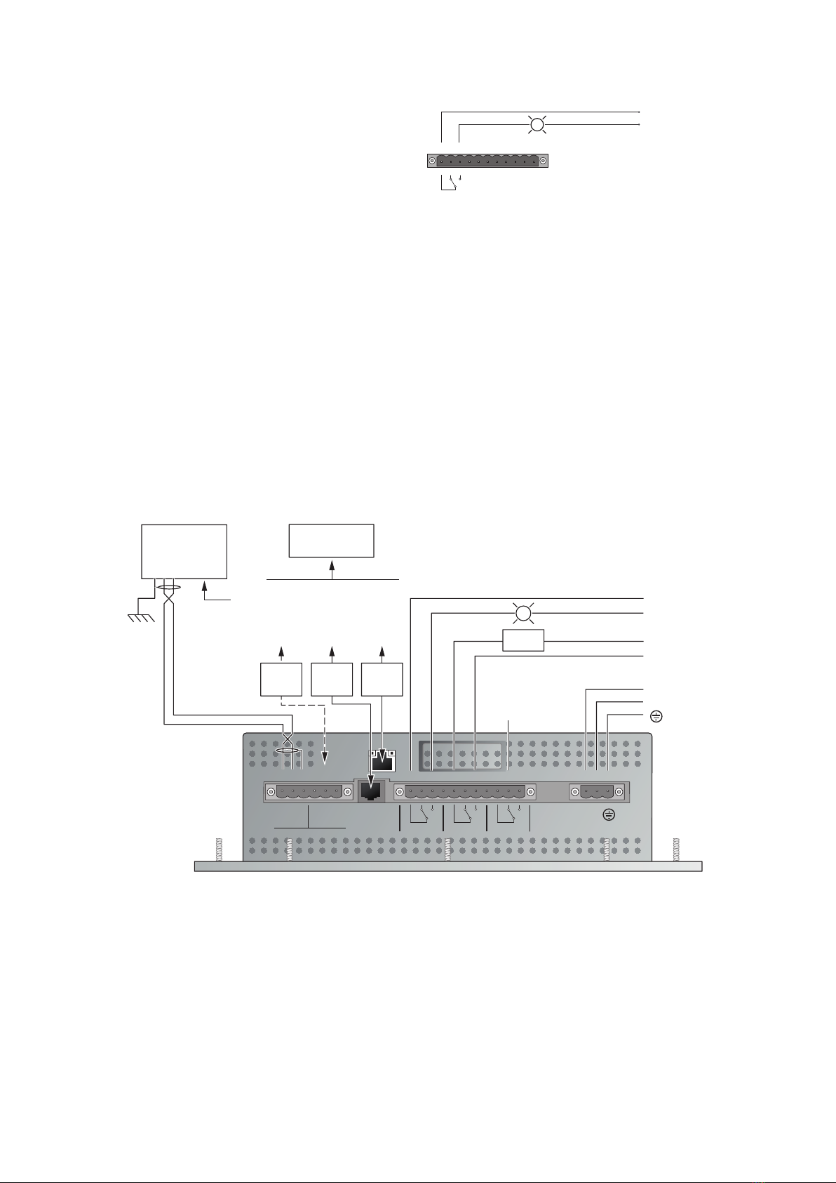
Control Outputs
Relay outputs Three relay outputs, SPDT contacts,
switching loads up to 277 VAC/3 A
Relays may be assigned for alarm outputs
11 position Phoenix-style pluggable screw
terminal connector with retaining screws
Network Connection
Local port/ remote RS-485/RS-232, selectable. Port may be used
to communicate with Supervisor Software
RS-232 is non-isolated, RJ-11 connection
RS-485, 2-wire Isolated. Phoenix-style
pluggable screw terminal connector with
retaining screws. Maximum number of
devices 256. Fail safe design with optional
termination resistors
Data Rate to 2400 to 57600 baud
Maximum cable length for RS-485 not to
Field port RS-485 2-wire isolated. Used to
communicate with external nVent RAYCHEM
devices, such as NGC-30-CRM, MONI-RMC
and RMM2. Maximum cable length not
to exceed 1200 m (4000 ft). Cable to be
shielded twisted pair
Phoenix style pluggable screw terminal
connector with retaining screws. Maximum
number of devices 256. Fail safe design with
optional termination resistors
Data rate to 9600 baud
LAN 10/100 Base-T Ethernet port with Link and
Activity Status LEDs
USB port USB 2.0 Host port Type A receptacle
Status LEDs
Relay Three LEDs showing the ON/OFF Status
for each relay, LED ON indicates relay is
energized
Field Transmit and Receive activity
Local/Remote Transmit and Receive activity
USB host Three colors showing status:
Green = USB key inserted
Red = USB key fault
UIT status Three colors showing system status:
Green = Normal Condition
Red = Fault Condition
Yellow = loading software/configuration
LCD Display
Display LCD is a 16.6 cm (6.5 inch) QVGA, color
TFT transflective device with integral
CCFL backlight. (For use indoors or when
protected from direct sunlight)
Touch screen 4-wire resistive touch screen interface for
user entry. Usable with gloved fingers
Nonhazardous Locations
73/23/EEC: Low Voltage Directive
including amendments
89/336/EEC: Electromagnetic Compatibility
Directive including amendments
LR67275
(Russia, Kazakhstan, Belarus)
For other countries contact your local nVent representative.

4 | nVent.com
Overview of Installation Procedure for NGC-UIT
Page #
A. Provide suitable panel enclosure, and determine 2
locations for NGC-UIT-ORD assembly in panel
B. Cut opening and mount NGC-UIT-ORD on front of panel 3
C. Installing common alarm light 4
D. Connect power and communication to the UIT 4
E. Servicing 5
F. Cleaning 5
G. Configuration switches 5
H. Reset switch 5
I. Cutting template 7
A. Provide Suitable Panel Enclosure, and Determine Locations for NGC-UIT Assembly in Panel
1. Provide suitable panel enclosure
To protect its electronic components, the NGC-UIT must be
mounted in a minimum NEMA 1 enclosure. A IP 54 (NEMA 12)
or better enclosure is recommended. The NGC-UIT assembly
comes with a sealing gasket and hardware to mount the
enclosure.
Note: The RAYCHEM NGC-UIT is designed for operation in
ambient temperatures from –40°C to 65°C (–40°F to 149°F). If
the ambient temperature is outside this range, a space heater
and/or cooling fan will be required in the panel.
2. Determine locations for the NGC-UIT assembly in the
electricalpanel
The NGC-UIT should be located on the front of the panel near
eye level (for convenient viewing). The NGC-UIT assembly is an
electronic unit and must not be located where it will be exposed
to strong magnetic fields or excessive vibration.
C1
CB19
CB17
CB15
CB13
CB3
CB9
CB11
CB7
CB5
CB1
CB16
CB42
CB20
CB18
CB4
CB14
CB12
CB10
CB8
CB6
CB2
C2 C3 C4 C5 C6 C7 C8 C9 C10
CB23
CB25
CB27
CB29
CB21
CB26
CB28
CB30
CB22
CB24
CB31
CB33
CB35
CB37
CB39 CB40
CB36
CB32
CB34
CB38
1
3
5
7
9
19
17
15
13
11
29
27
25
23
21
39
37
35
33
31
2
4
6
8
10
12
14
16
18
20
30
28
26
24
22
32
34
36
38
40
PanelNGC-UIT-ORD
assembly location
Panel
door
Alarm
light
A
B
D
E
C
Kit Contents
Item Qty Description
A 1 NGC-UIT display
B 1 Sealing gasket
C 10 #8 washers (stainless steel)
D 10 #8/32 locknuts (stainless steel)
E 1 1.5 meter (5 feet) RS-232 adaptor cable

nVent.com | 5
B. Cut Opening and Mount NGC-UIT on Front of Panel
1. Locate the NGC-UIT on front of panel
Locate the NGC-UIT assembly on the front of the panel at a level
convenient for viewing. Make sure the cover on the back of the
assembly will not interfere with existing panel hardware.
(Refer to full size cut-out template with all dimensions
Cutting
Area
Cutting Template
140.7 mm
(5.54")
231 mm
(9.1")
Note: Cutting the opening for the display is a craft sensitive
procedure; if it is not done correctly, the panel door can
be damaged. The procedure for laying out and cutting the
opening for the display must be undertaken with care, and by
personnel qualified and experienced in panel construction.
2. Prepare and mark the position of the display opening and
mounting holes
• Use the cut-out template on page 7 to lay out the opening for
the NGC-UIT display.
• Apply two layers of masking tape around the outer perimeter
of the intended opening to prevent scratching the panel
surface with the jigsaw.
• Use the template on page 7 to mark the opening and the
mounting holes for the user interface assembly.
Note: The following steps are most easily accomplished if the
panel door is on a horizontal surface.
3. Cut the display opening
Cut the opening for the NGC-UIT with a jigsaw using a 24 TPI
blade. Take care not to damage the panel door. Remove all
rough edges and burrs with a metal file before proceeding.
4. Drill the mounting holes
Drill the 10 holes with a 5 mm (3/16 inch) drill bit to mount the
NGC-UIT assembly in the panel.
5. Position the gasket on the outside of the panel door
• Place the sealing gasket between the NGC-UIT and front side
of enclosure door.
6. Mount the user interface assembly onto the panel door
• Place the NGC-UIT assembly in position; the ten mounting
screws go through the ten holes on the NGC-UIT assembly
mounting plate (see figure below).
UIT
display
Sealing
gasket
Panel
door
Inside of
panel door
UIT
display
• Place a #8 washer and #8/32 locknut on each of the ten
mounting studs; fasten only hand tight.
• Look at the front of the panel, and align the NGC-UIT
assembly so it is level (loosen nuts if necessary to reposition
the NGC-UIT assembly).
• After the display and gasket are properly positioned, tighten
the nuts to 1.13 Nm (Newton Meter) of torque using an 11/32
inch nut driver.
Do not overtighten and risk damage to hardware.

6 | nVent.com
Power and Earth Ground
1. Connect 100 to 240 VAC ±10% to AC input terminals (Line/L1
and Neutral/L2). Maximum wire size is 2.5 mm²
Ensure that branch circuit breaker does not exceed 15A and is
installed in accordance with local electrical codes.
2. A ground conductor must be terminated at the ground terminal
Communication
Field side port
1. This port is used to communicate with ModBus devices.
Connections to these terminals should be a shielded, twisted
pair cable. (Belden CDT cable 8761 or equivalent, maximum
length is 1200 m [4000 feet]). For more information, refer to
the NGC-30 Programming Guide (Install-111) and the NGC-30
Installation Manual (install-114).
Local port
1. This port is used to communicate to a host computer and is
user selectable for either RS-232, RS-485 or ethernet.
2. If the RS-232 port is utilized, the supplied RJ-11 to RS-232
adaptor cable must be used. For more information, refer to
the NGC-30 Programming Guide (Install-111) and the NGC-30
Installation Manual (install-114).
NGC-30-CRM,
RMC or RMM
Fail Safe Relay Outputs AC inputRS-485 Ports
10/100
Ethernet
RS-232
(DCE)
Local
S
+
S
+– –
N/L2
Line/L1
SIG –
SIG +
Shield
SIG –
SIG +
Shield
11109 321876543
Relay 3Relay 2Relay 1
RemoteField
21654321
To next
NGC-30-CRM,
RMC or RMM
Chassis
GRD
RS-485
cable
RS-232
cable
Ethernet
cable
Load
Note: When using RS-485 communication,
use Belden cable 8761 or equivalent.
RS-485 cable must not exceed 4000 ft.
Note: Relays are shown in the energized position (without an alarm condition).
Up to
277 V AC
3 Amps
Typical of
Relay 2 N/L2 100 to
240 V AC
±10%
Line/L1
Relay 2
Relay 1
PC
R
Select either RS-232, RS-485 or
Ethernet. Refer to the NGC-30
Programming Guide (INSTALL-111),
and the NGC-30 Installation Manual
(INSTALL-114) for further details.
An alarm light must be installed on the front of the enclosure to
indicate when an alarm has occurred. Relay 1 has already been
programmed for this purpose, and must be connected as shown.
If desired, install a push-to-test alarm light and/or interposing
relay and test button.
11109876543
Relay 1
21
230 Vac
Relay 1
R
C. Installing Common Alarm Light
D. Connect Power and Communication to the NGC-UIT

nVent.com | 7
E. Servicing
The NGC-UIT contains no user-serviceable parts. Contact your nVent representative for
F. Cleaning
The touch screen area of the NGC-UIT may be cleaned with a damp or dry cloth. Typical
window cleaning agents may be applied to aid in the removal of dirt, dust and grease. Do not
use abrasive cleaners.
G. Configuration Switches
The configuration switches are found on the side of the NGC-UIT.
Refer to the table below for settings.
Switch
Position
CommentsOn Off
TERM R-FIELD
(Field Port Termination
Select) Terminates local
RS-485 network.
120 Ohm
Termination
Enabled
(Factory Default)
Termination
Disabled For the local FIELD RS-485
network. If this NGC-UIT is the
first or last RS-485 device in
the network, it must be set to
ENABLED/ON. If the NGC-UIT
is NOT the first or last device, it
must be set to DISABLED/OFF.
TERM R-REMOTE
(Remote Port
Termination Select)
Terminates remote
RS-485 network
connected to PC and
RAYCHEM Supervisor
software
120 Ohm
Termination
Enabled
Termination
Disabled
(Factory
Default)
For the REMOTE RS-485
network connected to a PC. If
this NGC-UIT is the first or last
RS-485 device in the remote
network, it must be set to
ENABLED/ON.
If the NGC-UIT is NOT the first
or last device, it must be set to
DISABLED/OFF.
WDT
(Watch Dog Timer)
WDT Enabled
(Factory Default) WDT
Disabled WDT should normally be
enabled
H. Reset Switch
The Reset switch can be found on the side of the NGC-UIT. A pointed object is required to
press the reset switch and restart the UIT software.
TX
TX
1
3
USB
RX FIELD
RX LOCAL/REMOTE
2 OUTPUT
RELAYS
STATUS
RESET
USB
OFF TERM R-FIELD
OFF TERM R-REMOTE
OFF WDT
ON
ON
ON
Side View

8 | nVent.com
This Page Purposely Left Blank

nVent.com | 9
Cutout
Area
231 mm (9.1 in)
47 mm (1.84 in)
Cutting Template
141 mm (5.54 in)
47 mm (1.84 in)
.ø5 mm (18 in)
76 mm (3.0 in)
54 mm (2.12 in)
54 mm (2.12 in)76 mm (3.0 in) 76 mm (3.0 in)
10 places
IMPORTANT:
Before using this cutting template you must make
sure it has printed to scale or you will damage your
panel door. Printers* and copiers may make reduc
-
tions from the original size. Please ensure the file
has printed at 100% scale by using a ruler to confirm
the dimensions are as marked on this template
.
*Adobe Acrobat may reduce the document layout by default to
fit a generic printer's margins. Make sure scaling is turned off.
6 mm (0.24 in)
6 mm (0.24 in)
6 mm (0.24 in)
6 mm (0.24 in)
Cut here

10 | nVent.com

nVent.com | 11
Montageanleitung
Beschreibung
Bei dem nVent RAYCHEM NGC-UIT-ORD und NGC-UIT-OUT handelt
es sich um im Schaltschrank eingebaute Farb-LCD-Displays mit
Touchscreen-Oberfläche, welche in Verbindung mit anderen
zugelassenen RAYCHEM-Steuer-, Regel- und Überwachungsgeräten
zum Einsatz kommen. Das NGC-UIT-ORD weist die Schutzart IP
54 (NEMA 12) auf. Die beste Lesbarkeit bietet das Display jedoch
im Innenbereich oder wenn es vor direkter Sonneneinstrahlung
geschützt ist. Das NGC-UIT-OUT weist die Schutzart IP 56
(NEMA 4X) auf. Sämtliche für den Einbau in einen geeigneten
Schaltschrank benötigten Befestigungsteile werden mitgeliefert.
In dieser Anleitung wird der Einbau des NGC-UIT in einen
Schaltschrank beschrieben. Die Anleitung ist ausschließlich für
Personal mit Erfahrung im Schaltschrankbau vorgesehen.
Erforderliches Werkzeug
• Klebeband • 5mm Bohrer
• 11/32"-Steckschlüssel • Stichsäge (Verwendung eines
• Metallfeile Sägeblatts aus unlegiertem Stahl
mit 24 TPI wird empfohlen)
Zulassungen/Zertifizierungen
Ex-Bereiche Nicht-Ex-Bereiche
Bei dieser Komponente handelt es sich um ein
elektrisches Gerät, das welches entsprechend den
Vorgaben eingebaut und betrieben werden muss,
damit der einwandfreie Betrieb sichergestellt ist
und die Gefahr eines Stromschlags oder eines
Brandes ausgeschlossen werden kann. Lesen Sie
diese wichtigen Warnhinweise und befolgen Sie
alle Montageanweisungen genau.
• Zulassungen und Leistungsangaben gelten
nur, wenn Originalteile verwendet werden.
Verwenden Sie keine Fremdkomponenten.
Die Abbildung zeigt ein im Schaltschrank
eingebautes Touchpanel NGC-UIT-ORD
Allgemeines
Betriebsspannung 100 – 240 VAC ±10%, .25 A max/25 VA, 50/60 Hz
Betriebstemperatur –40°C to 65° (–40°F to 149°F)
EMV Entspricht EN ………Störfestigkeit – Industrie
Störaussendung - Handel / Leichtindustrie
Vibration nach IEC-60068-2-6
Stoßbelastung nach IEC-60068-2-27
Abmessungen 260 mm Breite x 168 mm Höhe x 76 mm Tiefe
Steuerausgänge
Relaisausgänge Drei Relaisausgänge, einpolige
Wechselkontakte, max. Schaltstrom 3A bei
AC 277 V
Die Relais können Alarmausgängen
zugewiesen werden
11-poliger Phoenix-Stecker mit
Schraubanschlüssen
Netzwerkanschluss
Lokaler / RS-485/RS-232, wählbar. Der Anschluss
Remote-Anschluss kann zur Kommunikation mit der Supervisor-
Software genutzt werden.
RS-232 ist ein nicht isolierter RJ-11-Anschluss.
RS-485, 2-adrig, isoliert. Phoenix-Stecker mit
Schraubanschlüssen. Maximal 256 Geräte
zulässig optional mit Abschlusswiderstand.
Datenübertragungsgeschwindigkeit:
2.400 bis 57.600 Baud.
Maximale Kabellänge für RS-485 darf 1.200
m nicht überschreiten. Es ist abgeschirmtes
Kabel zu verwenden.
Feldanschluss RS-485, 2-adrig, isoliert. Dient zur
Kommunikation mit externen Geräten wie
nVent RAYCHEM NGC-30-CRM, MONI-
RMC und RMM2. Maximale Leitungslänge
darf 1.200 m nicht überschreiten. Es ist
abgeschirmtes Kabel zu verwenden.
Phoenix-Stecker mit Schraubanschlüssen.
Max. 256 Geräte zulässig, optional. mit
Abschlusswiderstand
Datenübertragungsgeschwindigkeit bis 9.600
Baud
LAN 10/100 Base-T Ethernet-Anschluss mit Link-
und Activity-Status-LEDs
USB-Anschluss USB 2.0 Standardstecker Typ A
Status-LEDs
Relais Drei LEDs zeigen den EIN-/AUS-Zustand der
einzelnen Relais an. (LED an = Relais eingeschaltet)
Feld Sende- und Empfangsaktivität
Lokal/Remote Sende- und Empfangsaktivität USB-Verbindung
USB host Drei Farben dienen als Statusanzeige:
Grün = USB-Verbindung vorhanden
Rot = USB-Verbindung fehlerhaft
Gelb = USB-Verbindung akitiv
UIT-Status Drei Farben zeigen den Systemstatus an:
Grün = Normalbetrieb
Rot = Alarm
Gelb = Software/Konfiguration wird geladen
LCD-Display
Display Grafisches 16" TFT Farbdisplay mit
integrierter Hintergrundbeleuchtung
Touchscreen Resistiver 4-Draht Touch Screen für
Benutzereingaben, mit Handschuhen
bedienbar
LR67275
Klasse 1, Div. 2,
Gruppen A, B, C, D, T4
Klasse 1, Zone 2
Gruppen IIC, T4
LR67275
73/23/EWG: Niederspannungs-
richtlinie mit
Abänderungen
89/336/EWG: Richtlinie über
die elektro-
magnetische
Verträglichkeit mit
Abänderungen
Sollten sich Anweisungen oder Informationen sowohl auf das
NGC-UIT-ORD, als auch das NGC-UIT-OUT beziehen, wird das
Bedienterminal als NGC-UIT ohne die Erweiterung -ORD oder –
BEDIENTERMINAL FÜR RAYCHEM NGC-SYSTEME FÜR DEN EINSATZ IN INNENRÄUMEN UND
IMFREIEN

12 | nVent.com
Übersicht Montageanleitung NGC-UIT
Seite #
A. Schaltschrankgehäuse auswählen und Einbauort des 10
NGC-UIT-ORD im Schaltschrank festlegen
B. Öffnung ausschneiden und NGC-UIT-ORD an 11
der Schaltschrankvorderseite montieren
C. Leuchte Sammelstörmeldung einbauen 12
D. Strom- und Kommunikationsleitung am UIT anschließen 12
E. Servicearbeiten 13
F. Reinigung 13
G. Konfigurationsschalter 13
H. Reset-Schalter 13
I. Schablone zum Ausschneiden 15
A. Schaltschrankgehäuse auswählen und Einbauort des NGC-UIT im Schaltschrank festlegen
1. Schaltschrankgehäuse
Zum Schutz seiner elektronischen Bauteile muss das
NGC-UIT in ein Gehäuse eingebaut werden, welches mindestens
die Schutzart IP 54 oder höher aufweist. Im Lieferumfang des
Touchpanels NGC-UIT sind eine Dichtung sowie Kleinmaterial
zur Befestigung enthalten.
Anmerkung: Das RAYCHEM NGC-UIT ist für den Betrieb bei
Umgebungstemperaturen von –40°C bis 65°C ausgelegt. Liegt
die Umgebungstemperatur außerhalb dieses Bereichs, muss
der Schaltschrank mit einer geregelten Schaltschrankheizung
bzw. einem Lüfter ausgestattet werden.
2. Einbauort des NGC-UIT festlegen
Das NGC-UIT muss, damit es problemlos ablesbar ist, an der
Schaltschranktüre in Augenhöhe eingebaut werden. Beim
NGC-UIT handelt es sich um eine elektronische Baugruppe,
welche weder starken Magnetfeldern noch übermäßigen
Vibrationen ausgesetzt werden darf.
C1
CB19
CB17
CB15
CB13
CB3
CB9
CB11
CB7
CB5
CB1
CB16
CB42
CB20
CB18
CB4
CB14
CB12
CB10
CB8
CB6
CB2
C2 C3 C4 C5 C6 C7 C8 C9 C10
CB23
CB25
CB27
CB29
CB21
CB26
CB28
CB30
CB22
CB24
CB31
CB33
CB35
CB37
CB39 CB40
CB36
CB32
CB34
CB38
1
3
5
7
9
19
17
15
13
11
29
27
25
23
21
39
37
35
33
31
2
4
6
8
10
12
14
16
18
20
30
28
26
24
22
32
34
36
38
40
A
B
D
E
C
Lieferumfang
Position Menge Beschreibung
A 1 Touchpanel NGC-UIT-ORD
B 1 Dichtung
C 10 8/32" Unterlegscheiben (Edelstahl)
D 10 8/32" Gegenmuttern (Edelstahl)
E 1 RS-232-Adapterkabel (1,5 m)
Schalt-
schranktür
Einbauposition der
Baugruppe NGC-UIT-ORD
Schaltschrank
Alarmleuchte

nVent.com | 13
B. Einbauausschnitt anfertigen und NGC-UIT an der in der Schaltschranktüre montieren
1. NGC-UIT montieren
Montieren Sie die Baugruppe NGC-UIT in einer Höhe, welche
ein bequemes Ablesen des Displays ermöglicht. Vergewissern
Sie sich, dass das NGC-UIT nicht mit den Befestigungsteilen
und Verstrebungen des Schaltschranks in Berührung kommt.
Die Stabilität der Schaltschranktüre darf nicht beeinträchtigt
werden.
(Eine maßstabsgetreue Schablone zum Ausschneiden mit allen
Maßen finden Sie auf Seite 7.)
Auszuschneidender
Bereich
Schablobe
140.7 mm
(5.54")
231 mm
(9.1")
Anmerkung: Das Erstellen des Einbauausschnittes für
das Touchpanel erfordert sehr viel Geschick, da die
Schaltschranktür leicht beschädigt werden kann. Der
vorgesehene Ausschnitt muss vor dem Sägen sehr sorgfältig
markiert werden. Einbau und Anschluss des NGC-UIT darf
nur von qualifiziertem Fachpersonal durchgeführt werden.
2. Einbau / Befestigung des Touchpanels
• Markieren Sie den vorgesehenen Einbauort für das
Touchpanel NGC-UIT mit Hilfe der Schablone auf Seite 7.
• Umkleben Sie die markierte Schnittstelle mit zwei Schichten
Klebeband, damit die Oberfläche des Schaltschranks durch
das Sägen mit der Stichsäge nicht verkratzt wird.
• Markieren Sie die Montagebohrungen mit Hilfe der
Schablone.
Anmerkung: Die folgenden Schritte lassen sich am einfachsten
ausführen, wenn sich die Schaltschranktür auf einer
horizontalen Fläche befindet.
3. Öffnung für das Touchpanel ausschneiden
Schneiden Sie die Öffnung für das NGC-UIT mit einer Stichsäge
aus. Achten Sie dabei darauf, die Schaltschranktür nicht zu
beschädigen. Entfernen Sie alle rauen Kanten und Grate mit
einer Metallfeile, bevor Sie die weiteren Schritte ausführen.
4. Montageöffnungen bohren
Bohren Sie die 10 Öffnungen mit einem Bohrer M5, um das
Touchpanel NGC-UIT in den Schaltschrank einbauen zu können.
5. Dichtung außen an der Schaltschranktür anbringen
• Positionieren Sie die Dichtung zwischen das NGC-UIT und die
Vorderseite der Schaltschranktür.
6. Touchpanel in der Schaltschranktür montieren
• Setzen Sie das Touchpanel NGC-UIT in die Montageöffnung
ein und richten Sie es anschließend aus. Stecken Sie
die zehn Montageschrauben durch die Bohrungen in der
Schaltschranktüre gesteckt (siehe Abbildung unten).
• Setzen Sie eine Unterlegscheibe und eine Gegenmutter auf
jede der zehn Montageschrauben und ziehen Sie sie leicht
von Hand fest.
• Richten Sie die Baugruppe NGC-UIT gerade an der
Schaltschrankvorderseite aus. (Lösen Sie ggf. die Muttern,
um die Baugruppe NGC-UIT neu auszurichten.)
• Nachdem Touchpanel und Dichtung richtig positioniert
wurden, ziehen Sie die Muttern mit einem 11/32-Zoll-
Steckschlüssel auf ein Drehmoment von 1,13 Nm
(Newton-Meter) fest.
Ziehen Sie sie nicht übermäßig fest an, da die
Befestigungsteile sonst beschädigt werden könnten.
Schaltschranktür
Dichtung
UIT-Touchpanel
Innenseite der
Schaltschranktür
UIT-Touchpanel

14 | nVent.com
Stromversorgung und Erdschluss
1. Schließen Sie AC 100 bis 240 V ±10% an die Eingangsklemmen
(Phase/L1 und Neutralleiter/L2) an. Max. Leiterquerschnitt
Es ist sicherzustellen, dass der Leitungsschutzschalter im
Stromversorgungskreis 15 A nicht überschreitet. Örtliche
Vorschriften sind einzuhalten.
2. Ein Potentialausgleichskabel muss am vorgesehenen
Anschlusspunkt angeschlossen werden.
Kommunikation
Feldbus
1. Dieser Anschluss dient zur Kommunikation mit ModBus-
Geräten. Die Verbindungen zu diesen Anschlüssen müssen über
ein geschirmtes, verdrilltes Kabel erfolgen. (Belden-CDT-Kabel
8761 o. ä., max. 1.200 m). Weitere Informationen finden Sie im
Programmierhandbuch des NGC-30 (INSTALL-122) und in der
Montageanleitung des NGC-30 (INSTALL-124).
Lokaler Anschluss
1. Dieser Anschluss dient zur Kommunikation mit einem PC. Der
Benutzer hat die Wahl zwischen RS-232, RS-485 oder Ethernet.
2. Wenn der Anschluss RS-232 gewählt wird, muss das mitgelieferte
RJ-11-/RS-232-Adapterkabel verwendet werden. Weitere
Informationen finden Sie im Programmierhandbuch des NGC-30
(INSTALL-122) und in der Montageanleitung des NGC-30
(INSTALL-124).
D. Strom- und Kommunikationsleitung am NGC-UIT anschließen
NGC-30-CRM,
RMC oder RMM
Alarm-Relaisausgänge BetriebsspannungRS-485 Anschlüsse
10/100
Ethernet
RS-232
(DCE)
Local
S
+
S
+––
N/L2
Line/L1
SIG –
SIG +
Shield
SIG –
SIG +
Shield
11109321876543
Relay 3Relay 2Relay 1
RemoteField
21654321
Zum nächsten
NGC-30-CRM,
RMC oder RMM
Chassis-
Masse
RS-485
Kabel
RS-232-
Kabel
Ethernet-
Kabel
Last
Anmerkung:Bei Auswahl der RS-485-Kommunikation
verwenden Sie das Belden-Kabel 8761 o. ä.
Die RS-485-Leitung darf 1,2 km nicht überschreiten.
Anmerkung:Die Relais sind drahtbruchsicher (in eingeschaltetem Zustand, keine Störung) dargestellt.
max.
AC 277 V / 3 A
Relais 2
(typisch) N/L2
AC 100 bis
240 V ±10 %
Leitung/L1
Relais 2
Relais 1
PC
R
Wählen Sie RS-232, RS-485 oder
Ethernet. Weitere Einzelheiten sind
im Programmierhandbuch des
NGC-30 (INSTALL-122) und in der
Montageanleitung des NGC-30
(Install 124) beschrieben.
An der Vorderseite des Gehäuses muss eine Alarmleuchte
montiert werden, um Störungen anzuzeigen. Relais 1 wurde zu
diesem Zweck bereits vorprogrammiert und muss wie abgebildet
angeschlossen werden.
Alternativ können Sie einen Leuchtdrucktaster bzw. ein
Koppelrelais und eine Prüftaste montieren.
11109876543
Relay 1
21
230 Vac
Relay 1
R
C. Leuchte Sammelstörmeldung montieren

nVent.com | 15
E. Servicearbeiten
Das NGC-UIT enthält keine vom Benutzer zu wartenden
Teile. Wenden Sie sich an den Vertreter von nVent, falls
Wartungsarbeiten anfallen oder eine Autorisierungsnummer
benötigt wird.
F. Reinigung
Der Touchscreen-Bereich des NGC-UIT kann mit einem feuchten
oder trockenen Tuch gereinigt werden. Verschmutzung, Staub
und Fett lassen sich mit handelsüblichem Fensterreiniger leicht
entfernen. Verwenden Sie keine Scheuermittel.
G. Konfigurationsschalter
Die Konfigurationsschalter sind seitlich am NGC-UIT angebracht.
Die Einstellungen können Sie der Tabelle unten entnehmen.
Schalter
Position
AnmerkungenOn Off
TERM R-FIELD
(Auswahl des
Feldanschlusses)
schließt das lokale
RS485-Netzwerk ab.
120-Ohm-
Anschluss
aktiviert
(Werkseinstel-
lung)
Anschluss
deaktiviert Für das lokale RS485-FELD-
Netzwerk. Wenn dieses
NGC-UIT das erste oder letzte
RS485-Gerät im Netzwerk ist,
muss es auf AKTIVIERT/ON
gesetzt werden. Wenn das
NGC-UIT nicht das erste oder
letzte Gerät ist, muss es auf
DEAKTIVIERT/OFF gesetzt
werden.
TERM
R-REMOTE
(Auswahl
des Remote-
Anschlusses)
schließt das
RS485-Netzwerk ab,
welches an den PC
und die RAYCHEM
Supervisor-Software
angeschlossen ist.
120-Ohm-
Anschluss
aktiviert
Anschluss
deaktiviert
(Werkseinstel-
lung)
Für das RS485-REMOTE-
Netzwerk, welches an einen
PC angeschlossen ist. Wenn
dieses NGC-UIT das erste
oder letzte RS485-Gerät im
Netzwerk ist, muss es auf
AKTIVIERT/ON gesetzt werden.
Wenn das NGC-UIT nicht das
erste oder letzte Gerät ist,
muss es auf DEAKTIVIERT/
OFF gesetzt werden.
WDT
(Watch Dog Timer)
WDT aktiviert
(Werkseinstel-
lung)
WDT deaktiviert WDT sollte eingeschaltet sein
H. Reset-Schalter
Der Reset-Schalter ist seitlich am NGC-UIT angebracht. Zum
Betätigen des Reset-Schalters und Neustarten der UIT-Software
wird ein spitzer Gegenstand benötigt.
TX
TX
1
3
USB
RX FIELD
RX LOCAL/REMOTE
2 OUTPUT
RELAYS
STATUS
RESET
USB
OFF TERM R-FIELD
OFF TERM R-REMOTE
OFF WDT
ON
ON
ON
Seitenansicht

16 | nVent.com
Diese Seite wurde absichtlich leer gelassen

nVent.com | 17
Auszuschneidender
Bereich
231 mm (9.1 in)
47 mm (1.84 in)
Schablone zum Ausschneide
n
141 mm (5.54 in)
47 mm (1.84 in)
.ø5 mm (18 in)
76 mm (3.0 in)
54 mm (2.12 in) 54 mm (2.12 in)76 mm (3.0 in) 76 mm (3.0 in)
10 places
WICHTIG:
Bevor Sie diese Schablone zum Ausschneiden verwenden,
müssen Sie sich vergewissern, dass sie maßstabsgetreu
gedruckt wurde.
Drucker* und Kopierer können die Originalgröße verkleinert
wiedergeben. Bitte achten Sie da
rauf, dass die Datei im
Maßstab 1:1 (100 %) gedruckt wurde. Prüf
en Sie mit einem
Lineal nach, ob die Abmessungen den Markierungen auf
dieser Schablone entsprechen.
*Adobe Acro
bat kann das Dokumenten-Layout standardmäßig verkleiner
t
wiedergeben, um es an die üblichen Randeinstellungen des Druckers anzupassen.
Vergewissern Sie sich, dass die Skalierung deaktiviert wurde.
6 mm (0.24 in)
6 mm (0.24 in)
6 mm (0.24 in)
6 mm (0.24 in)
Hier ausschneiden

18 | nVent.com

nVent.com | 19
Instructions d’installation
Description
Le nVent RAYCHEM NGC-UIT-ORD et le NGC-UIT-OUT sont des
afficheurs à utiliser en association avec d'autres équipements agréés
de régulation et de surveillance RAYCHEM. Le NGC-UIT-ORD est
classifié IP 54 (NEMA 12). L'affichage sera toutefois plus facilement
lisible à l'intérieur d'un bâtiment ou à l'abri de la lumière directe du
l’afficheur est lisible tant à l’intérieur qu’à l’extérieur. Les kits NGC-UIT
incluent tout le matériel requis pour procéder au montage dans une
armoire électrique. Les instructions qui suivent sont exclusivement
destinées à des électriciens expérimentés et expliquent comment
monter le NGC-UIT dans une armoire électrique.
Outillage
• Ruban de masquage
• Clé à douille 11/32"
• Lime métallique
• Foret #16 (3/16)
• Scie sauteuse (utiliser de
préférence une lame au
carbure avec 24 TPI)
Agréments/Certifications
Zones explosibles Zones non explosibles
Classe 1, Div. 2,
Groupes A, B, C, D, T4
Classe 1, Zone 2
Groupes IIC, T4 73/23/EEC: Directive basse
tension avec
amendements
89/336/EEC: Directive
Compatibilité
électromagnétique
avec amendements
LR67275
LR67275
Ce composant est un équipement électrique qui
doit être installé dans les règles de l’art pour
garantir un fonctionnement correct et prévenir
tout risque d’électrocution ou d’incendie. Lisez
et respectez scrupuleusement les instructions
d’installation.
• Les agréments et performances des
composants sont basés sur l’utilisation
exclusive de pièces spécifiées. Ne pas
utiliser de pièces de substitution.
Kit NGC-UIT-ORD monté
dans une armoire électrique
Généralités
Tension d’alimentation 100 – 240 V ca ±10%, max. 0,25 A/25 VA,
Températures de service –40°C à 65°
CEM Immunité – Industrie
Émissions – Commerce / Industrie légère
Vibrations Unité testée selon IEC-60068-2-6
Résistance aux chocs Unité testée selon IEC-60068-2-27
Dimensions Largeur 260 mm, hauteur 168 mm,
Sorties de régulation
Sorties relais Trois sorties relais, contacts unipolaires
bidirectionnels, calibrés jusqu'à 277 V ca/3 A
Les relais peuvent être affectés aux sorties
d’alarme
Bornier enfichable à rétention de vis type
Phoenix, 11 positions
Connexion réseau
Local port/ remote RS-485/RS-232, à sélectionner. Le port
peut être utilisé pour communiquer avec le
logiciel Supervisor
RS-232 non isolé, connexion RJ-11
RS-485, 2 fils isolés. Bornier enfichable à
rétention de vis type Phoenix. Maximum 256
appareils. Mode de sécurité avec résistances
d’extrémité en option.
Débit données de 2400 à 57600 bauds
La longueur maximale de câble pour RS-485
ne peut dépasser 1200 m. Câble blindé à
paire torsadée
Port terrain RS-485, 2 fils isolés. Utilisé pour
communiquer avec des appareils externes,
tels que nVent RAYCHEM NGC-30-CRM,
MONI-RMC et RMM2. La longueur maximale
de câble ne peut dépasser 1200 m. Câble
blindé à paire torsadée
Bornier enfichable à rétention de vis type
Phoenix. Maximum 256 appareils. Mode
de sécurité avec résistances d’extrémité en
option.
Débit données jusqu’à 9600 bauds
LAN Port Ethernet 10/100 Base-T avec diodes
d’état de connexion et d’activité
Port USB USB 2.0 Port hôte Réceptacle Type A
Témoins lumineux
Relais Trois témoins lumineux affichant le statut
MARCHE/ARRÊT de chaque relais; un témoin
allumé indique que le relais est sous tension
Site Transmission et réception
Local/Distant Transmission et réception
Hôte USB Trois couleurs, correspondant aux statuts
suivants:
Vert = clé USB introduite
Rouge = erreur clé USB
Jaune = USB en cours d’utilisation
Statut UIT Trois couleurs, correspondant aux statuts
système suivants:
Vert = Normal
Rouge = Erreur
Jaune = Chargement de logiciel/
configuration
Affichage LCD
Affichage L’écran LCD 16,6 cm est un appareil couleur
QVGA, TFT transflectif à rétroéclairage CCFL
intégré (pour utilisation à l’intérieur ou à l’abri
de la lumière directe du soleil)
Écran tactile Interface résistive écran tactile à 4 fils pour
entrée utilisateur. Fonctionne également
avec des gants
Lorsqu’une instruction ou une information concerne à la fois
le NGC-UIT-ORD et le NGC-UIT-OUT, l’interface utilisateur est
appelée NGC-UIT, sans mention de l’extension -ORD ou -OUT
TERMINAL D'INTERFACE UTILISATEUR (UIT) INTÉRIEUR ET EXTÉRIEUR POUR SYSTÈMES
RAYCHEM NGC

20 | nVent.com
Procédure d'installation du NGC-UIT
Page #
A. Prévoir un boîtier adapté et déterminer l’emplacement
du NGC-UIT dans l’armoire électrique 2
B. Pratiquer une découpe et monter le NGC-UIT
sur l’avant du panneau. 3
C. Installer un témoin lumineux 4
D. Brancher l’alimentation électrique et les câbles de
communication du terminal 4
E. Mise en service 5
F. Nettoyage 5
G. Commutateurs de configuration 5
H. Touche de remise à zéro 5
I. Gabarit de découpe 7
A. Prévoir un boîtier adapté et déterminer l’emplacement du NGC-UIT dans
l’armoireélectrique
1. Prévoir un boîtier adapté
Pour protéger les composants électroniques, le NGC-UIT doit
être monté dans un boîtier de catégorie NEMA 1 ou supérieure.
Il est recommandé d’opter pour un boîtier IP 54 (NEMA 12) ou
supérieur. Le kit NGC-UIT est fourni avec un joint d’étanchéité et
les éléments requis pour le montage sur l’armoire électrique.
Remarque: Le RAYCHEM NGC-UIT est conçu pour fonctionner
à des températures comprises entre –40°C et +65°C. Au-delà
de ces températures ambiantes, installer un chauffage et/ou un
ventilateur dans l’armoire.
2. Déterminer l'emplacement du NGC-UIT dans l'armoire
électrique
Installer le NGC-UIT à l’avant de l’armoire électrique, au niveau
des yeux (pour plus de commodité). Le kit NGC-UIT contient
des composants électroniques et ne doit donc pas être exposé
à des champs magnétiques intenses ou à des vibrations
excessives.
C1
CB19
CB17
CB15
CB13
CB3
CB9
CB11
CB7
CB5
CB1
CB16
CB42
CB20
CB18
CB4
CB14
CB12
CB10
CB8
CB6
CB2
C2 C3 C4 C5 C6 C7 C8 C9 C10
CB23
CB25
CB27
CB29
CB21
CB26
CB28
CB30
CB22
CB24
CB31
CB33
CB35
CB37
CB39 CB40
CB36
CB32
CB34
CB38
1
3
5
7
9
19
17
15
13
11
29
27
25
23
21
39
37
35
33
31
2
4
6
8
10
12
14
16
18
20
30
28
26
24
22
32
34
36
38
40
Armoire
électrique
Emplacement du
NGC-UIT-ORD
Porte
Témoin
lumineux
A
B
D
E
C
Contenu du kit
Référence Qté Description
A. 1 Afficheur NGC-UIT-ORD
B. 1 Joint d’étanchéité
C. 10 Rondelles #8 (acier inoxydable)
D. 10 Écrous de serrage #8/32 (acier inoxydable)
E. 1 1,5 mètre de câble adaptateur RS-232
Other manuals for Raychem NGC-UIT-ORD
1
This manual suits for next models
1
Table of contents
Languages: