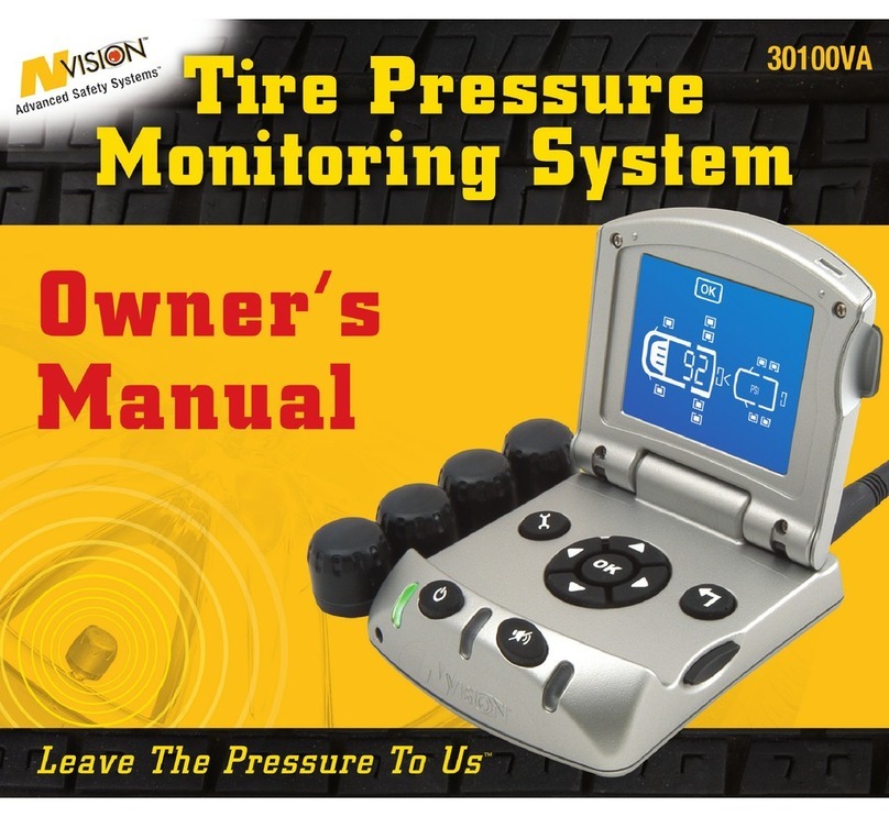
NVision 30100VA User manual

1

2
WELCOME
Thank you for purchasing our nVISION®Tire Pressure Monitoring System … the most sophisticated and
robust TPMS technology available!
This product is designed to give you years of reliable performance. If you have any questions about this product,
how to set it up or how to use, do not return it to the dealer where you bought it.
Instead, call our expert customer support team toll free at (800) 835-0129. Our tech service team is available
between the hours of 8am to 5pm CST, Monday through Friday.
NOTE: All warranties must be registered within 30 days of purchase. You can also visit
www.nVisionSafety.com to complete the warranty registration form, or call our customer support team
at the toll free number above.

3
TABLE OF CONTENTS
INITIAL INSTALLATION
Get Your TPMS Ready.............................................................................................................................................5-10
Boosting Your Signal ................................................................................................................................................. 11
Display Screen - Alerts ........................................................................................................................................19-20
Getting The Most From Your TPMS ......................................................................................................................... 21
YOUR NEW TPMS SYSTEM
Tire Safety Alerts........................................................................................................................................................ 12
TPMS Components..................................................................................................................................................... 13
Monitor Power Buttons............................................................................................................................................. 14
Navigation And Control Buttons.............................................................................................................................. 15
TPMS Warnings.......................................................................................................................................................... 16
Display Screen............................................................................................................................................................ 17
Edit Settings................................................................................................................................................................. 18
INFORMATION
Frequently Asked Questions................................................................................................................................22-27
FCC Compliance.......................................................................................................................................................... 28
Warranty Information............................................................................................................................................29-30
System Specifications............................................................................................................................................... 31

GETTING STARTED
It is important to read and understand your owner’s manual. It contains valuable information
as well as tips or suggestions for getting the most from your new TPMS System.
There are 3 basic installation steps:
1. Make sure you have the correct pressure in your tires before you install the system. It is best to install the
system in the morning when your tires are cool.
2. Turn on the monitor and scroll through the vehicle options that match your exact tire configuration.
Press the button to confirm your selection.
3. The system will ask you to install sensors one-by-one for each configuration. Locate the tire that corresponds to
the blinking tire symbol on your monitor. Screw the sensor on. When the pressure registers correctly, press .
You have established a unique electronic signature for that tire. Follow the prompts for all other tires.
Your nVISION®TPMS has a unique memory feature that allows you to store other configurations (trailers, vehicles,
motorhomes, etc.). Follow the same set up procedures for up to 4 different vehicles.
That’s it! Simple. Straight-forward. You’re now ready to roll….enjoy and be safe!!
4

5
GET YOUR TPMS READY
ACTIVATE
•Before you power up your TPMS system for the first time, you will need to attach the pivoting antenna. You will
find an antenna port in the back of the monitor. Screw the pivoting antenna into the port. Be careful not to over-
tighten the antenna.
TIP: The pivoting antenna provides flexibility and you can position to maximize signal strength from
sensors to the monitor. Also, easily pivots to fit into tight compartments in your RV.
•Insert Quick-Set™Installation Cord into the front of the monitor
for power. System will default to PSI. At initial start up, unit
will default to memory position #1
TIP: The Quick-Set™Installation Cord allows you to take the
monitor with you tire by tire for a faster and easier installation
experience.
Quick-Set™Installation Cord
(9-volt battery not included)
P
I
V
O
T
I
N
G

PSI
DEFINE MODE
When you turn your monitor on for the first time, your screen should look like
this. The “Define” Mode allows you to choose a wheel configuration that
exactly matches your vehicles and trailers.
TIP:We recommend that you program your most common driving
configurations into Memory Position 1 and 2.
Press the arrow keys to scroll through our menu of tire configurations to find
the correct configuration for your vehicle. For example, If you have a 10-wheel
motorhome scroll to this configuration
Stop on correct vehicle configuration and press to confirm selection
REMEMBER: Please take your monitor with you to each tire using the Quick-Set™Installation Cord.
NOTE:It is critical that you place the sensor on the tire that corresponds to the
flashing tire on the monitor. The system will store this specific sensor location into
memory. If you don’t put the sensor on the corresponding tire location, the pressure
will be read and reported properly, but the display will not provide the correct tire
location.
The monitor will advance to sensor installation on the tires. You will begin with the left front
tire. Please follow the diagram below when installing the sensors for your vehicle.
6
START

PSI
7
The monitor will advance to the next sensor location to install. Repeat the
same steps to complete the installation on all tires you will be monitoring.
SPARE TIRES: We recommend monitoring your spare tire so that
you know it is ready in the event of a tire failure. If you don’t want to
monitor this tire, move the curser to “NO” while this tire is blinking
and press “OK” to confirm. The system will advance to the next tire.
IMPORTANT: After you press on the last sensor in memory
position 1, monitor will advance to memory position 2 to install
your next vehicle or trailer configuration.
Press to move to Memory Position 2 and repeat the same steps
as you did for Memory Position 1 to complete your installation.
Once you have installed all of your vehicles or trailers you wish to
monitor. Use the navigational buttons and scroll to “SAVE” and
Press to exit Define Mode and enter Vehicle Position Mode.
PSI
PSI
The front left tire will begin flashing. This is where the first sensor
needs to be attached
Screw the sensor on the valve stem
The “YES” icon on the screen will be flashing. Wait for the correct
pressure to appear
Press after the correct pressure appears on the monitor

PSI
8
VEHICLE POSITION MODE
After saving your last memory position the system advances to Vehicle Position
Mode. This mode allows you to choose among the vehicles or trailers you have
stored.
TIP: In Vehicle Position Mode all defined vehicles or trailers will display
on the RIGHT side of the screen. Once positions are selected for front
and or back, the icons will display in the assigned positon.
“FRONT” icon is flashing, Press
Select the memory position you wish to monitor in the “FRONT” (The front
vehicle will be located on the LEFT hand side of the screen in normal mode)
Press to confirm
“BACK” icon is flashing, Press
Select the memory position you want to monitor in the “BACK” (The back
vehicle will be located on the RIGHT hand side of the screen in normal mode).
Press to confirm.
If you only want to monitor 1 vehicle, select “FRONT” or “Back” for
that vehicle. Then scroll to “SAVE” and Press to advance to
normal mode.
TIP: Only 1 “Front” and 1 “Back” Vehicle Configuration can be monitored
at a time.
“SAVE” icon will be flashing on the screen. Press to save your vehicle
configuration and advance to normal mode.
PSI
PSI

9
NORMAL OPERATION
Once you have completed programming your Memory Positions, your system
will enter normal operating mode. Your TPMS system will begin checking
your tires. You will see a series of check marks illuminate in the middle on
the right side of the display screen. These checks indicate that your TPMS
system is reestablishing the RF connections with each sensor and verifying
tire conditions. When all tire conditions report at normal levels, checking
will stop and your monitor will illuminate the green light.
If you have turned your monitor off, you will need to turn it on to begin the
normal operation mode. Note that from the off position, your TPMS system
will need to reestablish the RF signature for each sensor for the Memory
Positions last used. This process could take up to 5 minutes depending on the communication cycle of the sensors.
When the monitor reestablishes RF connections, the monitor will display a yellow light, to indicate that it has yet to
verify all tire conditions.
TIP: We recommend that once your system is operating, you leave it plugged in and turned on. This ensures that
you have a continuous monitoring of all tires. If your vehicle is to be parked for more than 30 days, we recommend
you turn the monitor off.
PSI
This is what your screen should
look like in Normal Mode.

10
PSI
CHANGING YOUR VEHICLE POSITION
When in Normal Mode, Press the Vehicle Position Button on the monitor.
CAUTION: Pressing the Vehicle Position Button will clear all memory
positions that have been saved in the “FRONT” or “BACK” Position
“FRONT” icon is flashing, Press
Select the memory position you wish to monitor in the “FRONT” (The front
vehicle will be located on the LEFT hand side of the screen in normal mode)
Press to confirm
“BACK” icon is flashing, Press
Select the memory position you would like to monitor in the “BACK” (The back
vehicle will be located on the RIGHT hand side of the screen in normal mode)
Press to confirm.
“SAVE” icon will be flashing on the screen. Press to save your vehicle
configuration and advance to normal mode.
When all tires report within normal tire conditions, the green light will
illuminate.
PSI
PSI

11
BOOSTING YOUR SIGNAL
RF (Radio Frequency) signals are commonly used in wireless devices. The RF frequencies in your nVISION TPMS
system conform to all FCC Rules.
The RF system in your TPMS device has been designed to use normal objects in the environment to reverberate
signals from the wheels to the monitor. In normal use, most environments will provide the necessary impediments
to reverberate signals.
You may have occasion where an absence of objects on one side of your vehicle may not allow certain sensor
signals to be received by the monitor. If this should happen, you will receive a missing sensor signal. While this
error is likely to be rare, it can occur.
Different vehicles and longer distances can also affect the quality of your signal reception. If you are
experiencing excessive missing sensor notifications, we recommend you add an nVISION®Repeater.
This is available at a modest additional cost through our Customer Care Team (800) 835-0129.
30300VA TPMS Repeater

12
Your New
nVISION TPMS
Offers 5 Total
Tire Safety
Features
!
STOP
!
STOP
!
STOP
!
STOP

2. Pivoting Antenna
13
nVISION® TPMS COMPONENTS
Your nVISION®TPMS Has 6 Basic Components
1. A specially designed monitor that has a unique flip top to improve viewing angles.
2. A pivoting antenna that will attach to the monitor base.
3. A special non-skid pad designed for vinyl dash boards to help prevent the monitor from
sliding while driving.
4. An electrical cord to power the monitor. The cord plugs into a 12-volt outlet or
cigarette lighter.
5. Four (4) electronic tire pressure sensors. Note that additional sensors can be purchased
separately for additional tires. We recommend that you also purchase a sensor for your
spare tire to ensure you have a replacement should you ever experience a tire failure.
6. Quick-Set™installation cord that plugs into the monitor during the setup process for power.
This helps install your system in minutes. Requires a 9-volt battery (not included) to work.
1. Monitor 3. Non-Skid Pad
6. Quick-Set™Cord
(9-volt battery not included)
5. Sensors
4. Power Cord

MONITOR POWER BUTTONS
There are two buttons on the face of the monitor (See Illustration B).
On/Off Button: When the monitor is plugged into a 12-volt DC power source, pushing this button will
power on or power off the monitor. For best results, we recommend that you always leave your monitor
on. This provides a continuous monitoring connection with your tire sensors. If you are just powering up
the monitor, it may take a couple of minutes for the connection between the sensors and monitor to
be reacquired. The electrical draw of the monitor is insignificant and should not affect the vehicle battery.
Volume Button: This button allows you to adjust the volume and mute the system.
There are 4 sound levels:
Mute = Press Volume Button Once
Low = Press Volume Button Twice
Medium = Press Volume Button Three Times
High = Press Volume Button Four Times
Pressing the Volume Button a Fifth Time recycles to mute. Keep pressing the symbol until it is at
the desired level.
14
Illustration B: Monitor Face Buttons
On/Off Volume

15
NAVIGATION AND CONTROL BUTTONS
Press the Quick-Release Button on the right side of the monitor and the display screen will open to
reveal your navigation and control buttons.
Selection “OK”
Has up/down/left/right arrows with a OK push
button in the center. This allows you to move
the cursor to different options and confirm your
selections. You can also use the arrows to check
your tire pressures
Vehicle Configuration (Define Mode)
To initiate programming of all vehicle/trailer
configurations
Position
To change the configuration of what vehicle you
want to drive and/or tow
Undo
To erase programming choices or back up in the
programming mode to previous selections
Edit Sensor
To enter a programmed vehicle configuration to
add/delete sensors
Quick-Release
Button
BATTERY NOT
INCLUDED

16
TPMS WARNINGS
Illustration C:
Warning Lights
On the face of the monitor (Illustration C) you will find 3 different colored lights. These lights are designed to
provide a quick reference to the status of your tires.
!
STOP
!
STOP
!
STOP
!
STOP
!
STOP
!
STOP
Dangerously Low
Pressure Alert (25%)
High Temperature
High Pressure Alert
Low Pressure Alert
(12.5%)
Low Battery
Missing Sensor
TIP: We recommend that
while the green light is lit,
which indicates all tires
are reporting normal tire
conditions, you keep the
monitor display closed.
This will minimize driver
distractions.
GREEN
This means you are saving money
by maximizing your fuel economy
and tire tread life.
YELLOW ALERTS
(Yellow Light Will Flash)
These warnings do not need your
immediate attention. Please get off
the road at your next convenient stop.
RED ALERTS
(Red Light Will Flash With Audible
Tone Beeps For 5 Seconds)
Please get off road immediately to
prevent a tire failure!

17
DISPLAY SCREEN - ALERTS
The LCD has been designed to provide you with an exact match to the tire configuration for your driving and towing
situations. It gives you the power to view your tire conditions from the comfort of your driver’s seat … whether
you’re moving or stationary … and regardless of whether conditions.
TIP: Your nVISION®TPMS will not prevent tires from losing pressure or failing. Your new system is
designed to detect and notify you of changing tire conditions.
GREEN – Tire
conditions are safe
YELLOW – Please pull
off the road at next
convenient stop
RED – Get off the road
immediately to avoid
tire failure
Low Tire Pressure
(12.5% LOW)
Volume Control
Low Battery
Dangerously Low Tire
Pressure (25% LOW) High Tire Pressure High Tire
Temperature
Missing Sensor
All tires are
functioning
correctly
Identifies what
mode your in
Save all changes
to your system
Memory Positions

18
EDITING SETTINGS
ADDING/DELETING SENSORS
Once you have completed your vehicle/towed vehicle selections, you will be able to add or delete specific
tire or sensor locations. For example, you may need to change out a sensor due to a low battery. Follow the steps
below to complete:
To add a sensor, Press the “Sensor Edit” Button on the monitor.
Move to the specific tire, press
This will illuminate “YES/NO”. To add, “YES” will be flashing and confirm by pressing .
Install sensor on corresponding tire and wait for the correct tire pressure reading.
Press to confirm and to accept sensor.
To delete, select “NO” and press
Press “Sensor Edit” Button to save and exit Sensor Edit Mode

19
Your nVISION TPMS has a unique 5-Level Alert System
SAFE TIRE CONDITIONS: Properly inflated tires are safer, run cooler and last longer. Also, helps increase fuel
economy and tire tread life by 50% or more. This alert means all tire all good. The GREEN light on the front of the
monitor will be illuminated.
LOW PRESSURE: At 12.5% below the baseline pressure level, you will receive this alert. The YELLOW light on the
monitor will begin to flash and will flash continuously until the low pressure condition has been resolved. To ensure
that you are aware of the alert, a corresponding signal tone will sound with the YELLOW light. It will beep for 5
seconds. If you want to silence the warning signal, simply press the volume control button to “MUTE” the sound of
the alert. The display screen will show the accepted symbol of low tire pressure.
Tires 12.5% low are not considered dangerous, but you may begin to notice a slight deterioration in vehicle handling.
Certainly, you will be experiencing reduced fuel economy. In addition, you will be creating excessive tire wear.
If you receive a Level 1 Alert, we suggest that you get off the road at the first convenient opportunity and air up the
tire(s) to proper levels.
If you want to see which tire or tires have experienced a pressure loss, open the display screen. Tires with low
pressures will flash. If you have only one low tire, the monitor will display that tire, along with the current tire
pressure. If you have more than one 12.5% below normal pressure, all low tires will flash. You can use the arrow
keys to review the pressure levels in each tire.
MISSING SENSOR: There are several possible reasons for a missing sensor. If your system loses communication
with a sensor, this will trigger the YELLOW light on the front of the monitor to illuminate. NO audible warning will
alert you because while it is important to know you lost a sensor it does not require your immediate attention. To
determine which sensor is missing, open your display screen and you will see a missing sensor icon flashing. In
addition, the tire position of the missing sensor will also flash. If the RF signal connection has been interrupted, it
could take several minutes to reestablished the connection.
LOW BATTERY: Approximately 2 weeks prior to expiration, the sensor will send a notification to the monitor
indicating low battery. This will trigger the YELLOW light and the display screen will illuminate the low battery icon.
!
STOP
!
STOP
!
STOP

20
DANGEROUSLY LOW PRESSURE: At 25% below the baseline pressure level, you will receive this alert. The RED
light on the monitor will begin to flash and will flash continuously until the low pressure condition has been resolved.
To ensure that you are aware of the alert, a continuous signal tone will sound with the RED light for 5 seconds. If you
want to silence the warning signal, simply press the volume control button to “MUTE” the sound of the alert. The
monitor display will also illuminate a STOP sign to indicate the dangerous driving condition.
Tires 25% low are considered DANGEROUS. You will feel a deterioration in control and performance. It is imperative
that you exit the roadway at the first safe opportunity. You should immediately air up the tire(s) to proper levels.
If you want to see which tire or tires have experienced a pressure loss, open the display screen. Tires with
dangerously low pressures will flash. If you have only one low tire, the monitor will display that tire, along with the
current tire pressure. If you have more than one 25% below normal pressure, all low tires will flash. You can use the
arrow keys to review the pressure levels in each tire.
HIGH PRESSURE: At 24% ABOVE the baseline pressure level, you will receive this alert. The RED light on the
monitor will begin to flash and will flash continuously until the high pressure condition has been resolved. To ensure
that you are aware of the alert, a corresponding signal tone will sound with the RED light. It will beep for 5 seconds.
If you want to silence the warning signal, simply press the volume control button to “MUTE” the sound of the alert.
The monitor display will also illuminate a HIGH PRESSURE ICON to indicate the dangerous driving condition.
Over-inflated tires cause uneven wear on the tread of your tires making your tires not last as long. You will also
notice a decrease in vehicle handling and braking performance.
HIGH TEMPERATURE: At 176° F or 80° C, you will receive this alert. The RED light on the monitor will begin to
flash and will flash continuously until the high temperature condition has been resolved. To ensure that you are
aware of the alert, a corresponding signal tone will sound with the RED light. It will beep for 5 seconds. If you want
to silence the warning signal, simply press the volume control button to “MUTE” the sound of the alert. The monitor
display will also illuminate a HIGH TEMPERATURE ICON to indicate the dangerous driving condition.
Hot tires increase your risk of a blowout. If you receive this alert notification please exit the roadway as soon as
possible and let your tires cool down.
!
STOP
!
STOP
!
STOP
TIP: Once errors are corrected it can take up to 5 minutes for the correction to register on the monitor.
Table of contents
Other NVision Measuring Instrument manuals
Popular Measuring Instrument manuals by other brands

Omron
Omron H7CX - datasheet

BESAFE
BESAFE Digital Safety user manual

Datacolor
Datacolor SpyderTV quick start guide

Macherey-Nagel
Macherey-Nagel NANOCOLOR Advance Operating instruction

Airflow Instruments
Airflow Instruments AV 30 operating instructions

DENT Instruments
DENT Instruments PowerScout 12 HD quick start guide