Copyright 2017 NVT Phybridge | 413-0004-1 | 2017/07 | Page 2
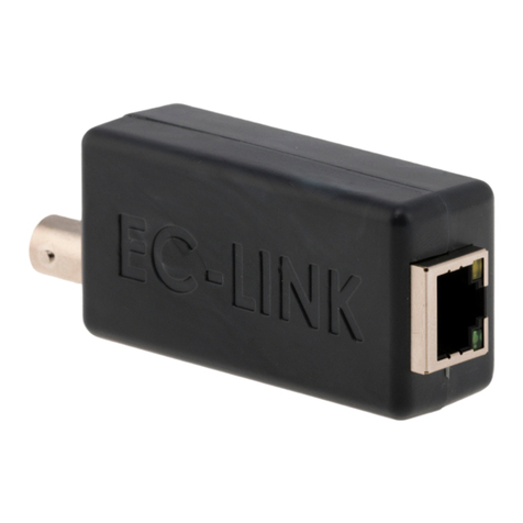
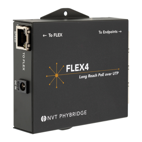
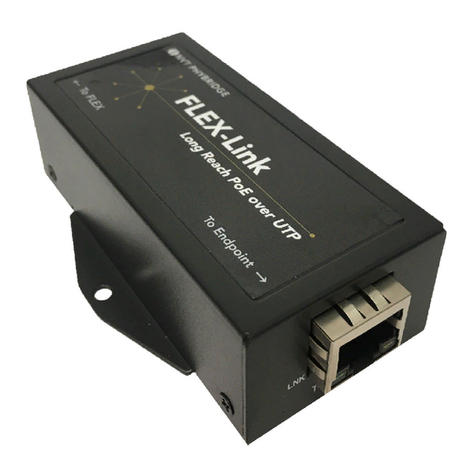
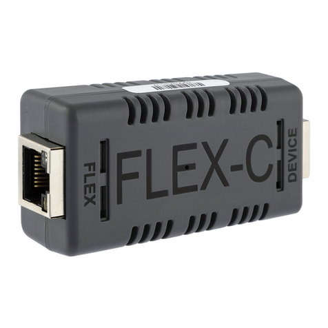
1 RJ45 port: UTP cable (2-pair or 4-pair)
4 pair CAT5e
Cable Type
1 pair CAT5e
2 pair CAT5e
2 pair CAT5e
100 Mbps
Data Rate
100 Mpbs
10 Mbps
100 Mbps
610m/ 2000ft
Reach
610m/2000ft
300m/1000ft
300m/1000ft
(adapter must be locally powered)
QUICK INSTALL GUIDE - FLEX EXTENDER KIT
888.901.3633 | +44 (0) 208 977 6614 | www.nvtphybridge.com Copyright 2017 NVT Phybridge | 445-0004-1 | 2017/07 | Page 2888.901.3633 | +44 (0) 208 977 6614 | www.nvtphybridge.com
Note the Following:
All of the above instructions provide basic
installation information necessary for the proper
and safe functioning of this equipment. Persons
installing or maintaining this product must read
all of the safety instructions and the parts of
system grounding, which are applicable to the
system being maintained. Only trained, qualified
service personnel shall install or maintain this
product.
WARNINGS
FAILURE TO FOLLOW ALL INSTRUCTIONS
MAY RESULT IN IMPROPER EQUIPMENT
OPERATION AND/OR RISK OF ELECTRICAL
SHOCK.
ANY CONNECTION TO AN OUTSIDE PLANT
LEAD, AN OFF-PREMISE APPLICATION, OR
ANY OTHER EXPOSED PLANT APPLICATION
MAY RESULT IN A FIRE OR SHOCK HAZARD,
AND/OR DEFECTIVE OPERATION, AND/OR
EQUIPMENT DAMAGE.
Keep these instructions with the equipment.
Do not attempt to install or service this
equipment unless you are skilled in the
installation and maintenance of electronic
telecommunications equipment and have
successfully completed specific training for this
equipment.
Compliance and
Environmental Information
All the compliance and environmental
information is available on our website
www.nvtphybridge.com.
Technical Support
The NVT Phybridge Technical Support Group is
available to assist you with product installation,
configuration, monitoring and troubleshooting
procedures. Should you experience trouble with
this equipment or for repair or warranty
information, please contact NVT Phybridge at
Safety Warnings
Refer to the FLEX24 or FLEX8 Quick Install
Guides under “Safety Warnings” for the FLEX
adapters
Reportez-vous aux Quick Install Guides
FLEX24 ou FLEX8 sous “Safety Warnings”
pour les adaptateurs FLEX
Beachten Sie die FLEX24- oder FLEX8- Quick
Install Guides unter “Safety Warnings” für die
FLEX-Adapter
Consulte las Quick Install Guides FLEX24 o
FLEX8 bajo “Safety Warnings” para los
adaptadores FLEX
Katso FLEX24- tai FLEX8 Quick Install Guides
FLEX-sovittimien “Safety Warnings” alla
Raadpleeg de FLEX24 of FLEX8 Quick Install
Guides onder “Safety Warnings” voor de
FLEX-adapter
Se FLEX24 eller FLEX8 Quick Install Guides
under “Safety Warnings” för FLEX-adaptrarna
Ανατρέξτε στους οδηγούς FLEX24 ήFLEX8
Quick Install Guides στην ενότητα “Safety
Warnings” για τους προσαρμογείς FLEX
Fare riferimento alla sezione FLEX24 o FLEX8
Quick Install Guides sotto “Safety Warnings”
per gli adattatori FLEX
Consulte o FLEX24 ou FLEX8 Quick Install
Guides em “Safety Warnings” para os
adaptadores FLEX
Irreferi għall-FLEX24 jew FLEX8 Quick Install
Guides taħt “Safety Warnings” għall-adapters
FLEX
Vaadake FLEX24 või FLEX8 Quick Install
Guides alusel “Safety Warnings” FLEX
adapterid
A FLEX adapterek “Safety Warnings” című
részében olvassa el a FLEX24 vagy a FLEX8
Quick Install Guides című részt
Nanašajo na FLEX24 ali FLEX8 Quick Install
Guides pod "Safety Warnings" za FLEX
adapterji
Další informace naleznete v příručkách
FLEX24 nebo FLEX8 Quick Install Guides v
části "Safety Warnings" pro adaptéry FLEX
Kreiptis į FLEX24 ar FLEX8 Quick Install
Guides pagal "Safety Warnings" Už FLEX
adapteriai
Skatiet FLEX24 vai FLEX8 Quick Install Guides
zem "Safety Warnings,” lai FLEX adapteri
Pozrite si FLEX24 alebo FLEX8 Quick Install
Guides v časti "Safety Warnings" pre
adaptéry FLEX
Sjá FLEX24 eða FLEX8 Quick Install Guides
undir "Safety Warnings " fyrir FLEX-millistykki
Zobacz FLEX24 lub FLEX8 Quick Install
Guides w sekcji "Safety Warnings" w
przypadku adapterów FLEX
Se FLEX24 eller FLEX8 Quick Install Guides
under "Safety Warnings" for FLEX-adaptere
Consultați ghidurile FLEX24 sau FLEX8 Quick
Install Guides din secțiunea "Safety
Warnings" pentru adaptoarele FLEX
Обърнете се към FLEX24 или FLEX8 Quick
Install Guides в"Safety Warnings" за
адаптери FLEX.


