NVT Phybridge FLEX24-10G User manual

242220181614
232119171513
12108642
1197531
Installation Details
Quick Install Guide - FLEX24-10G
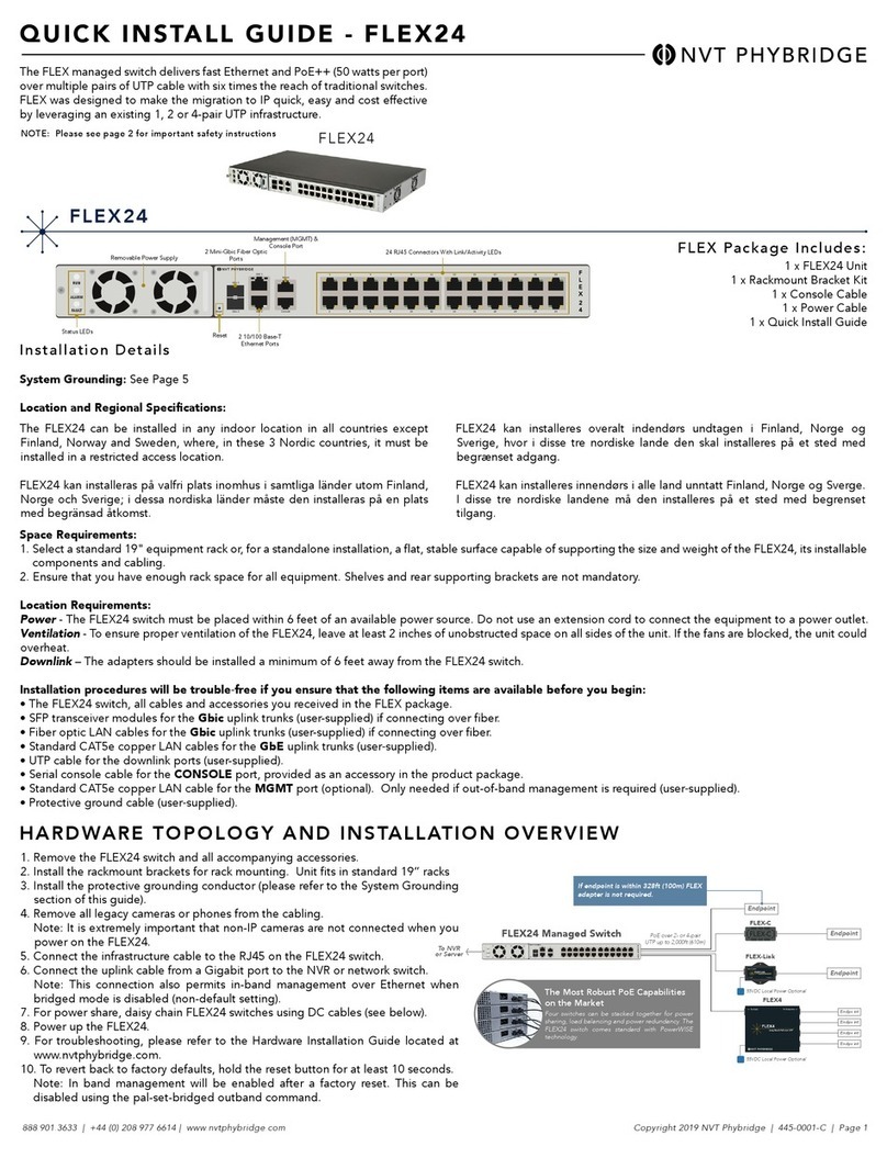
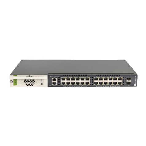
The FLEX24-10G Layer 3 managed switch delivers Gigabit Ethernet and PoE++
(50 watts per port) over multiple pairs of UTP cable with six times the reach of
traditional switches. FLEX was designed to make the migration to IP quick, easy
and cost effective by leveraging an existing 1, 2 or 4-pair UTP infrastructure.
Status LEDs
Removable
Power Supply Management (MGMT)
& Console Port 24 RJ45 Connectors With
Link/Activity LEDs
Reset 2 SFP+ Ports
1 x FLEX24-10G Unit
1 x Rackmount Bracket Kit
1 x Console Cable
1 x Power Cable
1 x Quick Install Guide
FLEX24-10G Package Includes:
System Grounding: See Page 5
Location and Regional Specifications:
Space Requirements:
1. Select a standard 19" equipment rack or, for a standalone installation, a flat, stable surface capable of supporting the size and weight of the FLEX24-10G, its
installable components and cabling.
2. Ensure that you have enough rack space for all equipment. Shelves and rear supporting brackets are not mandatory.
Location Requirements:
Power - The FLEX24-10G switch must be placed within 6 feet of an available power source. Do not use an extension cord to connect the equipment to a power outlet.
Ventilation - To ensure proper ventilation of the FLEX24-10G, leave at least 2 inches of unobstructed space on all sides of the unit. If the fans are blocked, the unit could
overheat.
Downlink – The adapters should be installed a minimum of 6 feet away from the FLEX24-10G switch.
Installation procedures will be trouble‐free if you ensure that the following items are available before you begin:
• The FLEX24-10G switch, all cables and accessories you received in the FLEX package.
• SFP/SFP+ transceiver modules for the 10G uplink ports (user-supplied).
• Fiber or UTP cable (user-supplied) for the SFP/SFP+ modules.
• UTP cable for the downlink ports (user-supplied).
• Serial console cable for the CONSOLE port, provided as an accessory in the product package.
• Standard CAT5e copper LAN cable for the MGMT port (optional). Only needed if out-of-band management is required (user‐supplied).
• Protective ground cable (user‐supplied).
The FLEX24-10G can be installed in any indoor location in all countries except Finland,
Norway and Sweden, where, in these 3 Nordic countries, it must be installed in a
restricted access location.
FLEX24-10G kan installeras på valfri plats inomhus i samtliga länder utom Finland,
Norge och Sverige; i dessa nordiska länder måste den installeras på en plats med
begränsad åtkomst.
FLEX24-10G kan installeres overalt indendørs undtagen i Finland, Norge og Sverige,
hvor i disse tre nordiske lande den skal installeres på et sted med begrænset adgang.
FLEX24-10G kan installeres innendørs i alle land unntatt Finland, Norge og Sverge. I
disse tre nordiske landene må den installeres på et sted med begrenset tilgang.
Hardware Topology & Installation Overview
1. Remove the FLEX24-10G switch and all accompanying accessories.
2. Install the rackmount brackets for rack mounting. Unit fits in standard 19”
racks.
3. Install the protective grounding conductor (please refer to the System
Grounding section of this guide).
4. Remove all legacy devices from the cabling. Note: It is extremely important that
non-IP devices are not connected when you power on the FLEX24-10G.
5. Connect the infrastructure cable to the RJ45 on the FLEX24-10G switch.
6. Connect a downlink or uplink port to the network switch.
7. For power share, daisy chain FLEX24-10G switches using DC cables (see below).
8. Power up the FLEX24-10G.
9. For troubleshooting, please refer to the Hardware Installation Guide located at
www.nvtphybridge.com.
10. To revert back to factory defaults, hold the reset button for 50 seconds or until
the fault (!) LED on the power supply stops flashing red. Alternatively, factory
reset can be observed by connecting the console cable; command line of
switch will confirm that factory reset has occurred during the boot process.
Copyright 2020 NVT Phybridge | 445-0030 REV. B | Page 1888.901.3633 | +44 (0) 208 977 6614 | www.nvtphybridge.com
PoE over Multi-Pair UTP up to 2,000ft (610m)
FLEX4
FLEX4
Long Reach PoE over UTP
FLEX-Link
FLEX-C
FLEX-Link
LongReach PoE over UTP
IP Endpoint
IP Endpoint
IP Endpoint
IP Endpoint
IP Endpoint
IP Endpoint
Local Power
Option
Local Power
Option
To Application
FLEX24-10G
The Most Robust PoE Capabilities on the Market
Four switches can be stacked together for power sharing and power
redundancy. The FLEX24-10G switch comes standard with PowerWISE
technology.
IP Endpoint Functions like a normal PoE+ switch for distances up to 328ft (100m).
No adapter required.
All manuals and user guides at all-guides.com

IN OUT
IN OUT
IN OUT
IN OUT
Quick Install Guide - FLEX24-10G
Power Capabilities & Considerations
FLEX24-10G switches come standard with a hot swappable PowerWise power supply for power sharing. The switches are amongst the lowest power consuming
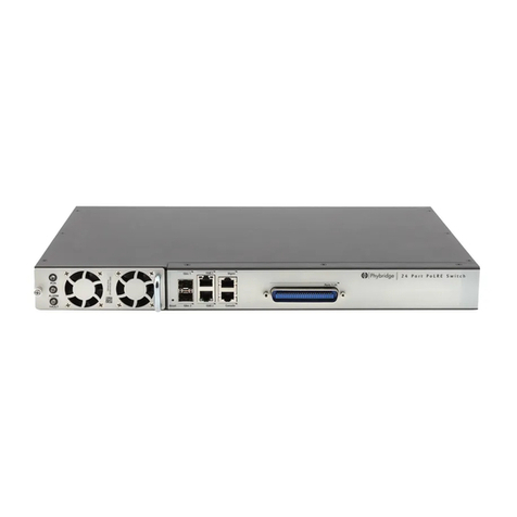
switches in the industry. For a redundant power configuration, daisy-chain multiple FLEX24-10G switches: You can connect up to a maximum of 4 units for
power sharing.
• Mount all FLEX24-10G switches in the same equipment rack, with no more than 1U space between any two
units.
•Note: You can daisy-chain the units together while they are up and running or power them up afterward.
• Facing the rear of the units, install the DC cables (available through Phybridge) as follows:
• Note: To fit properly, the DC cable must be inserted into the DC input/output connector with its hairpin clip on
top.
• For the top unit, insert the first cable into the DC input connector on the left until it clicks into place. Bring
the other end of the cable down to the next unit, and connect to the DC output connector on the right.
• Continue in the same way for each pair of units, connecting the DC input (left) connector on the upper unit
to the DC output (right) connector on the lower unit.
• Important: For the bottom unit, the last cable from the DC input (left) connector goes up to the DC output
(right) connector on the top unit. This is required to create a fully redundant ring.
Note: If you need to move a cable to a different DC connector on the FLEX24-10G, press the hairpin clip at
the top of the DC cable and pull the cable out.
Warning: All daisy-chained units must be set to the same voltage. By default, units are set to 56VDC.
Configuring the FLEX24-10G (2 Methods)
Connecting to the Admin GUI
Accessibility:
• Out of band management available through
the management port.
Default IP Address:
• MGMT = 192.168.1.1
• VLAN 1 = 192.168.100.1
Default Username & Password:
• Username: admin
• Password: admin
Steps to Change the IP Address:
1. Click on ETHERNET menu option on the top bar.
2. Once Ethernet page is displayed select Uplink Ports.
3. Type in the new IP address and prefix into the "IP
Address / Prefix" field inside the "VLAN 1" panel.
Note: Either an IPv4 or IPv6 address can be used. To
use DHCP, enable the "DHCP" toggle.
4. Type in the new IP address of the default gateway into
the "Default gateway:" field.
5. Click the "Apply" button next to any fields which were
modified.
6. Refer to the admin guide for more software details.
Connecting to FLEX24-10G:
1. Change the IP address of your PC or Laptop to
192.168.1.2
2. Connect your Ethernet port on the PC or Laptop to the
MGMT port on the FLEX24-10G.
3. Open a web browser that is up to date and browse to
http://192.168.1.1
4. Login is “admin”, password is “admin” (without quotes).
5. You are now in the Admin GUI.
Note: Change IP addresses to avoid conflict.
(Ethernet/Uplink Ports)
Connecting to the Command Line Interface (CLI)
Accessibility:
• Console cable connected directly to the
console port.
Console Port Serial Settings:
• 115200/8/N/1
Default Username & Password:
• Username: admin
• Password: admin
Steps to Change the IP Address:
1. The following commands must be issued to change VLAN 1's IPv4
address:
configure terminal
interface vlan 1
ip address 192.168.9.1 255.255.255.0
Substitute the provided example IP information for your own.
a) The command syntax is: ip address <ipv4_address> <subnet_mask>
2. Refer to the CLI section of the administration guide for more
information.
Connect to the Console Port:
1. Connect the RJ45 end of the serial cable to the console
port of the FLEX24. Connect the serial end of the serial
cable to the serial port of your PC.
2. Configure your serial port to 115200/8/N/1.
3. Login is “admin”, password is ”admin” (without quotes).
4. You are now connected to the CLI via the console port.
Steps to Change the Management Port IP Address:
1. Log into the unit via the serial console port (115200,8,N,1,None).
2. The following commands must be issued to change the IP address of the
management port:
configure terminal
interface vlan 1001
ip address 192.168.10.1 255.255.255.0
Substitute the provided example IP information for your own.
a) The command syntax is: ip address <ipv4_address> <subnet_mask>
3. Refer to Chapter 1 of the Administration Guide for more information and how
to configure an IPv6 address.
Steps to Save the Configuration:
1. Type in “end” or issue ctrl+z on the keyboard to return to Privileged EXEC mode.
2. The configuration is saved by issuing the “copy running-config startup-config”
command.
3. The switch configuration has now been saved.
Copyright 2020 NVT Phybridge | 445-0030 REV. B | Page 2888.901.3633 | +44 (0) 208 977 6614 | www.nvtphybridge.com
All manuals and user guides at all-guides.com

Quick Install Guide - FLEX24-10G
Note the Following:
All of the above instructions provide basic installation information necessary for the proper and safe functioning of this equipment. Persons installing or maintaining this product must
read all of the safety instructions and the parts of system grounding, which are applicable to the system being maintained. Only trained, qualified service personnel shall install or maintain
this product.
Keep these instructions with the equipment.
Do not attempt to install or service this equipment unless you are skilled in the installation and maintenance of electronic telecommunications equipment and have successfully
completed specific training for this equipment.
WARNINGS
FAILURE TO FOLLOW ALL INSTRUCTIONS MAY RESULT IN IMPROPER EQUIPMENT OPERATION AND/OR RISK OF ELECTRICAL SHOCK.
ANY CONNECTION TO AN OUTSIDE PLANT LEAD, AN OFF-PREMISE APPLICATION, OR ANY OTHER EXPOSED PLANT APPLICATION MAY RESULT IN A
FIRE OR SHOCK HAZARD, AND/OR DEFECTIVE OPERATION, AND/OR EQUIPMENT DAMAGE.
• Access to the interior of this unit shall be made only by a qualified technician.
• This unit may have more than one power input. To reduce the risk of energy or shock hazard, disconnect all power inputs before servicing.
• To ensure adequate cooling of the equipment, a 2-inch unobstructed space must be provided around all sides of the unit.
• The Power Socket shall be installed near the equipment and shall be easily accessible
• To prevent the risk of shock or fire hazard, replace fuse with same type and rating.
CAUTION: The ground lug is a main earth terminal that must be permanently connected to earth.
• Der Zugang ins Innere des Gerätes ist nur einem fachlich qualifizierten Techniker gestattet.
• Dieses Gerät kann mehr als eine Leistungsaufnahme. Um das Risiko von Energie oder Gefahr eines elektrischen Schlags zu reduzieren, trennen Sie alle Macht Eingaben,
bevor Wartungsarbeiten an der Einheit.
• Um die Kühlung des Gerätes nicht zu beeinträchtigen, ist es notwendig, an allen Seiten des Gerätes ca 5 cm Raum zu lassen.
• Stellen Sie das Gerät in der Nähe eines geerdeten Schutzkontaktsteckers so auf,dass der Stecker leicht erreichbar und zugänglich ist.
• Zur Vermeidung der Stromschlag‐und Feuergefahr beim Auswechseln Sicherungen des gleichen Typs und der gleichen Nennleistung einsetzen.
VORSICHT: Die Erdungsöse ist einer der wichtigsten Erdungsklemme, die dauerhaft auf die Erde angeschlossen werden muss.
• Seul un spécialiste doit avoir accès l'appareil.
• Cette unité peut avoir plus d'une entrée d'alimentation. Pour réduire le risque de danger de l'énergie ou de choc, débranchez toutes les entrées d'alimentation avant de
réparer l'unité.
• Afin de ne pas nuire au processus de refroidissement, il est nécessaire de laisser un espace d'environ 5 cm de chaque côté de l'appareil.
• Placez l'appareil près d’une prise de courant facilement accessible.
• Afin d’éviter tout risque d’incendie ou d’électrocution, remplacez les fusibles par des fusibles de même type et de même ampérage.
ATTENTION: La cosse de terre est une borne de terre principale qui doit être connectée en permanence à la terre.
• El servicio de antenimiento y reparación de esta unitad solo puede ser realizado por técnicos autorizados por el fabricante.
• Esta unidad puede tener más de una entrada de energía. Para reducir el riesgo de peligro de descargas eléctricas o descargas eléctricas, desconecte todas las entradas de
alimentación antes de reparar la unidad.
• No bloquee las ranuras de ventilación del equipo, ya que los componentes podrian sobrecalentarse y sufrir daños.
• Para evitar el riesgo de choque electrico o de incendio, reemplace el fusible com otro del mismo tipo y capacidad nominal.
• Para su propia protección, cerciórese de que todas las conexiones eléctricas de los servicios públicos, incluyendo la puesta a tierra, las líneas telefónicas y el sistema de
tuberías de agua metálicas internas, si las hubiera, estén conectadas entre sí.
PRECAUCIÓN: El terminal de tierra es un terminal de tierra principal que debe estar permanentemente conectada a la tierra.
• L'accesso all'interno di questa unità `deve essere effettuata solo da un tecnico qualificato.
• Questo unisce possono avere più di un ingresso di potenza. Per ridurre il rischio di pericolo di energia o scosse, scollegare tutti gli ingressi di alimentazione prima di.
• Per garantire un adeguato raffreddamento dell'apparecchiatura, uno spazio libero da 2 pollici deve essere fornita intorno a tutti i lati dell'unità.
• The Power Socket `deve essere installata vicino all'apparecchio e` devono essere facilmente accessibili
• Per evitare che la prevenzione del rischio di scossa o di pericolo di incendio, sostituire il fusibile con lo stesso tipo e valore.
ATTENZIONE: Il capocorda è mano che il terminale di terra deve essere collegato a terra in modo permanente.
• Достъп до вътрешността на този уред трябва да се извършва само от квалифициран техник.
• Това устройство може да има повече от един вход. За да намалите риска от опасност от електрически или токов удар, изключете всички входове за захранване
преди извършване на сервиз.
• За да се осигури подходящо охлаждане на оборудването, трябва да се осигури 2-инчово свободно пространство около всички страни на устройството.
• Захранващият щепсел ще бъде инсталиран в близост до оборудването и ще бъде лесно достъпен
• За да предотвратите опасност от удар или пожар, сменете предпазителя със същия тип и квалификация.
ВНИМАНИЕ: Заземената ухо е основна заземяваща клема, която трябва да бъде постоянно свързана към земята.
• Juurdepääs interjööri selle üksuse tehakse ainult kvalifitseeritud tehnik.
• See üksus võib olla rohkem kui üks võimsustoide. Et vähendada energia või elektrilöögi vältimiseks lahutage kõik sisendvõimsus Enne hooldamist.
• Jahutuse tagamiseks seadme, 2-tolline vaba ruum peab olema ümber kõik küljed üksus.
• Pistikupesa peab olema seadme lähedal ning olema kergesti ligipääsetavad
• Selleks, et vältida riski ning tulekahjuoht, vaheta kaitse sama tüüpi ja hinnang.
ETTEVAATUST: Maapind kõrv on peamine Maa terminal peab olema püsivalt ühendatud maaga.
SAFETY WARNINGS AND PRECAUTIONS
Copyright 2020 NVT Phybridge | 445-0030 REV. B | Page 3888.901.3633 | +44 (0) 208 977 6614 | www.nvtphybridge.com
All manuals and user guides at all-guides.com

Quick Install Guide - FLEX24-10G
• Η πρόσβαση στο εσωτερικό της μονάδας πρέπει να γίνεται μόνο από εξειδικευμένο τεχνικό.
• Αυτή η μονάδα μπορεί να έχει περισσότερες από μία είσοδοι ισχύος. Για να μειώσετε τον κίνδυνο ηλεκτροπληξίας ή ηλεκτροπληξίας, αποσυνδέστε όλες τις εισόδους ισχύος
πριν από τη συντήρηση.
• Για να εξασφαλιστεί η κατάλληλη ψύξη του εξοπλισμού, πρέπει να υπάρχει ένας ελεύθερος χώρος 2 ιντσών γύρω από όλες τις πλευρές της μονάδας.
• Η πρίζα πρέπει να είναι εγκατεστημένη κοντά στον εξοπλισμό και να είναι εύκολα προσβάσιμη
• Για να αποφύγετε τον κίνδυνο κρούσης ή πυρκαγιάς, αντικαταστήστε την ασφάλεια με τον ίδιο τύπο και την ίδια βαθμολογία.
ΠΡΟΣΟΧΗ: Η προεξοχή γείωσης είναι ένας κύριος ακροδέκτης γείωσης που πρέπει να είναι μόνιμα συνδεδεμένος με τη γείωση.
• Piekļuve interjera šīs vienības veic tikai kvalificēts tehniķis.
• Šī vienība var būt vairāk nekā viena jaudas ievadi. Lai samazinātu risku, enerģijas vai strāvas triecienu, atvienojiet visus strāvas ieejas pirms apkopes.
• Lai nodrošinātu pietiekamu dzesēšanu iekārtu, 2 collu aizsegts telpu jānodrošina ap visām pusēm vienības.
• Power Socket jāuzstāda pie iekārtas, un jābūt viegli pieejamai
• Lai novērstu risku, ka trieciena vai ugunsgrēka briesmas, nomainīt drošinātāju ar tāda paša veida un reitingu.
UZMANĪBU: Zemes lug ir galvenais zemes terminālis, kas ir pastāvīgi savienots ar zemi.
• Prieiga prie šio įrenginio viduje, turi būti atlikti tik kvalifikuotas specialistas.
• Šis įrenginys gali turėti daugiau kaip vieno galios įvestį. Sumažinti energijos arba elektros smūgio pavojaus riziką, prieš aptarnaujant atjunkite visus maitinimo įėjimai.
• Siekiant užtikrinti tinkamą aušinimą įranga, 2 colių užgriozdinti erdvę turi būti pateikta apie visus įrenginio pusių.
• Maitinimo lizdas turi būti netoli įrenginio ir turi būti lengvai prieinama
• Siekiant užkirsti kelią šoko ar gaisro pavojus riziką, pakeiskite saugiklį su tos pačios rūšies ir įvertinimas.
ATSARGIAI: Pirmame rankena yra pagrindinis žemės terminalas, turi būti neišardomai sujungti į žemę.
• A készülék belsejét csak szakképzett szakember végezheti.
• Ennek a készüléknek több áramforrása is lehet. Az energia vagy az áramütés veszélyének csökkentése érdekében szüntesse meg az összes tápellátást a szervizelés előtt.
• A berendezés megfelelő hűtésének biztosítása érdekében egy 2 hüvelykes, akadálytalan helyet kell biztosítani a készülék minden oldalán.
• A tápegységet a berendezés közelében kell felszerelni, és könnyen hozzáférhetővé kell tenni
• Az ütésveszély vagy a tűzveszély elkerülése érdekében cserélje ki az azonos típusú és minősített biztosítékot
FIGYELMEZTETÉS: A földelőfülk egy olyan fő földelő kapocs, amelyet állandóan a földhöz kell csatlakoztatni.
• Toegang tot het interieur van dit toestel wordt alleen door een gekwalificeerde technicus uitgevoerd.
• Dit apparaat kan meer dan één stroominvoer hebben. Om het risico op energie- of schokgevaar te verminderen, moet u alle voedingsinvoer uitschakelen voordat u
onderhoudt.
• Om een adequate afkoeling van de apparatuur te garanderen, moet een 2-inch vrijstaande ruimte rondom alle kanten van het apparaat worden aangebracht.
• De stekker moet dichtbij de uitrusting worden geïnstalleerd en zijn gemakkelijk bereikbaar
• Om het risico op schokken of brandgevaar te voorkomen, vervang de zekering met hetzelfde type en de waarde.
VOORZICHTIG: De grondvliegtuig is een hoofdterminal die permanent op aarde moet worden aangesloten.
• Tilgang til det indre av denne enheten skal kun utføres av en kvalifisert tekniker.
• Denne enheten kan ha mer enn én strøminngang. For å redusere risikoen for energi eller støtfare, koble fra alle strøminngangene før service.
• For å sikre tilstrekkelig kjøling av utstyret, må det være 2 tommers uhindret plass rundt alle sider av enheten.
• Strømuttaket skal installeres i nærheten av utstyret og skal være lett tilgjengelig
• For å unngå fare for støt eller brannfare, bytt sikring med samme type og karakter.
FORSIKTIG: Jorden er en hoved jordterminal som må være permanent forbundet med jord.
• Dostęp do wnętrza tego urządzenia wykonuje tylko wykwalifikowany technik.
• Urządzenie może mieć więcej niż jedno wejście zasilania. W celu zmniejszenia ryzyka porażenia prądem lub porażenia prądem elektrycznym, przed przystąpieniem do obsługi
należy odłączyć wszystkie zasilanie.
• W celu zapewnienia odpowiedniego chłodzenia urządzenia, wokół wszystkich stron urządzenia musi być umieszczona 2-calowa przestrzeń bez przeszkód. • Gniazdo
zasilania powinno być zainstalowane w pobliżu urządzenia i powinno być łatwo dostępne
• Aby uniknąć ryzyka porażenia prądem lub pożaru, wymień bezpiecznik na ten sam typ i poziom.
UWAGA: Uziemienie jest głównym zaciskiem uziemienia, które musi być trwale połączone z ziemią
• O acesso ao interior desta unidade deve ser efectuado apenas por um técnico qualificado.
• Esta unidade pode ter mais de uma entrada de alimentação. Para reduzir o risco de energia ou choque elétrico, desconecte todas as entradas de alimentação antes de
realizar a manutenção.
• Para assegurar o resfriamento adequado do equipamento, um espaço sem obstruções de 2 polegadas deve ser fornecido em torno de todos os lados da unidade.
• O Power Socket deve ser instalado perto do equipamento e deve ser facilmente acessível
• Para evitar o risco de choque ou incêndio, substitua o fusível pelo mesmo tipo e classificação.
CUIDADO: O terminal de aterramento é um terminal de aterramento principal que deve ser permanentemente conectado à terra.
• Accesul la interiorul acestui aparat trebuie efectuat numai de către un tehnician calificat.
• Această unitate poate avea mai multe intrări de alimentare. Pentru a reduce riscul de pericol de energie sau de șoc, deconectați toate intrările de alimentare înainte de a
efectua lucrările de service.
• Pentru a asigura o răcire adecvată a echipamentului, trebuie prevăzut un spațiu liber de 2 inci pe toate laturile unității.
• Priza de alimentare trebuie instalată în apropierea echipamentului și trebuie să fie ușor accesibilă.
• Pentru a preveni riscul de șoc sau de pericol de incendiu, înlocuiți siguranța cu același tip și clasificare.
ATENȚIE: Urechea de împământare este un terminal principal de împământare care trebuie conectat permanent la pământ.
Copyright 2020 NVT Phybridge | 445-0030 REV. B | Page 4888.901.3633 | +44 (0) 208 977 6614 | www.nvtphybridge.com
All manuals and user guides at all-guides.com

Quick Install Guide - FLEX24-10G
• Dostop do notranjosti te enote se izvede le strokovnjak.
• Ta enota ima lahko več kot en vnos energije. Da bi zmanjšali tveganje za energijo ali udara, izvlecite vse napajalne vhodov pred servisiranjem.
• Da bi zagotovili ustrezno hlajenje opreme, mora 2-palčni neoviran prostor, je treba zagotoviti okoli vse strani enote.
• Vtičnica naj bo nameščena blizu opreme in zlahka dostopen.
• Da bi preprečili nevarnost udara ali nevarnosti požara, zamenjajte varovalko iste vrste in jakosti.
POZOR: Tla nos je glavni zemlja terminal, ki mora biti stalno povezan z zemljo.
• Prístup do interiéru tohto prístroja môže vykonať iba kvalifikovaný technik.
• Táto jednotka môže mať viac ako jeden vstupný výkon. Aby ste znížili riziko výskytu nebezpečenstva úrazu elektrickým prúdom alebo úrazu elektrickým prúdom, pred servisom
odpojte všetky napájacie vstupy.
• Aby bolo zabezpečené dostatočné chladenie zariadenia, musí byť okolo všetkých strán jednotky k dispozícii 2-palcový neobmedzený priestor.
• Sieťová zásuvka musí byť inštalovaná v blízkosti zariadenia a musí byť ľahko prístupná.
• Aby ste zabránili nebezpečenstvu výbuchu alebo požiaru, vymeňte poistku rovnakého typu a typu.
UPOZORNENIE: Uzemňovacia svorka je hlavná zemniaca svorka, ktorá musí byť trvalo pripojená k uzemneniu.
• Tämän laitteen sisätilojen saa suorittaa ainoastaan pätevä teknikko.
• Laitteessa voi olla enemmän kuin yksi virtalähde. Jos haluat vähentää energian tai sähköiskun vaaraa, irrota kaikki virtalähteet ennen huoltoa.
• Laitteen riittävän jäähdytyksen varmistamiseksi on järjestettävä 2 tuuman esteettömät tilat laitteen kaikkien puolien ympärille.
• Virtapistoke on asennettava lähelle laitetta ja sen on oltava helposti saatavilla.
• Vaihda sulake saman tyyppisellä ja luokalla, jotta iskun tai tulipalon vaara ei onnistu.
VAROITUS: Maadoituskappale on maadoitusliitin, joka on kytkettävä pysyvästi maahan.
• Tillgång till det inre av denna enhet ska endast utföras av en kvalificerad tekniker.
• Denna enhet kan ha mer än en strömingång. För att minska risken för energi- eller chockfare, koppla bort alla strömingångar före service.
• För att säkerställa tillräcklig kylning av utrustningen måste ett 2-tums fritt utrymme tillhandahållas runt alla sidor av enheten.
• Strömuttaget ska installeras nära utrustningen och vara lättillgängligt.
• För att undvika risk för chock eller brandfara, byt ut säkring med samma typ och betyg.
FÖRSIKTIGT: Jordslangen är en huvud jordterminal som måste vara permanent ansluten till jorden.
• Aðgangur að innanverðu þessa eininga skal aðeins gerð af viðurkenndum tæknimanni.
• Þessi eining getur haft fleiri en eina aflgjafa. Til að draga úr hættu á orku- eða lostáhættu skal aftengja öll inntak rafmagns fyrir þjónustu.
• Til að tryggja fullnægjandi kælingu búnaðarins verður að vera með 2 tommu óhindrað pláss fyrir alla hliðum tækisins.
• Rafmagnstengi skal komið fyrir nálægt búnaði og skal vera aðgengilegur.
• Til að koma í veg fyrir hættu á losti eða eldhættu skal skipta um öryggi með sömu tegund og einkunn.
VARÚÐ: Jörðin er aðal jarðstöðvar sem verður að vera varanlega tengdur við jörðina.
• Aċċess għall-intern ta 'din l-unità għandha ssir biss minn tekniku kkwalifikat.
• Din l-unità jista 'jkollhom qawwa aktar minn wieħed. Biex jitnaqqas ir-riskju ta 'enerġija jew xokk periklu, skonnettja l-inputs kollha ta' enerġija qabel servicing.
• Biex jiġi żgurat tkessiħ adegwat tat-tagħmir, 2-pulzier spazju mhux mfixkel għandhom ikunu provduti madwar naħat kollha tal-unità.
• Il Socket Qawwa għandha tkun installata ħdejn it-tagħmir u għandhom ikunu aċċessibbli faċilment.
• Biex ikun evitat ir-riskju ta 'xokk jew perikolu ta' nar, jissostitwixxu fjus bil istess tip u ratifika.
ATTENZJONI: Il lug art huwa terminal prinċipali art li għandha tiġi mqabbda b'mod permanenti mal-art.
• Adgang til det indre af denne enhed skal kun foretages af en kvalificeret tekniker.
• Denne enhed kan have mere end en strømindgang. For at reducere risikoen for energi eller stødfare skal du afbryde alle strømindgange inden service.
• For at sikre tilstrækkelig afkøling af udstyret skal der være en 2-tommers uhindret plads på alle sider af enheden.
• Stikkontakten skal installeres i nærheden af udstyret og skal være let tilgængeligt.
• For at undgå risiko for stød eller brandfare udskiftes sikringen med samme type og rating.
FORSIGTIG: Ground lug er en hoved jord terminal, der skal være permanent forbundet til jorden
• Pristup unutrašnjosti ove jedinice obavlja samo ovlašteni tehničar.
• Ova jedinica može imati više od jednog ulaznog napajanja. Da biste smanjili opasnost od opasnosti od strujnog udara, isključite sve napajanje prije servisiranja. • Kako bi se
osiguralo odgovarajuće hlađenje opreme, na svim stranama uređaja mora se osigurati neometan prostor od 2 inča.
• Utičnica napajanja mora biti instalirana blizu opreme i mora biti lako dostupna.
• Da biste spriječili opasnost od udara ili opasnosti od požara, zamijenite osigurač istom vrstom i ocjenom.
OPREZ: Podnožje za uzemljenje je glavni zemaljski terminal koji mora biti trajno spojen na zemlju.
All the compliance and environmental information is available on our website www.nvtphybridge.com.
Compliance and Environmental Information
Technical Support
The NVT Phybridge Technical Support Group is available to assist you with product installation, configuration, monitoring and troubleshooting
procedures. Should you experience trouble with this equipment or for repair or warranty information, please contact NVT Phybridge Inc. at +1 905.901.3633
Copyright 2020 NVT Phybridge | 445-0030 REV. B | Page 5888.901.3633 | +44 (0) 208 977 6614 | www.nvtphybridge.com
All manuals and user guides at all-guides.com

Quick Install Guide - FLEX24-10G
System Grounding (Earthing)
Protective grounding conductor
Install the protective grounding conductor to the system.
General grounding
Cabinets always require redundant and independent equipment grounding conductors between the cabinet and the wiring system ground: an insulated grounding
conductor and a supplementary (protective) ground.
Grounding conductor
The grounding conductor is provided as part of the three-wire, 15-Amp, AC-power cord set included with the equipment. If the power cord must be replaced, use a
power cord of the same gauge that has the same insulation, number of conductors, and usage ratings.
GROUND ALL SYSTEMS ACCORDING TO THESE INSTRUCTIONS BEFORE YOU CONNECT POWER LEADS.
FOLLOW INSTRUCTIONS EXPLICITLY TO ENSURE THE SAFETY OF PERSONNEL.
The ground symbol within a circle identifies the terminal to be connected to an external protective conductor. Connect this terminal to earth
ground before you make any other connections to the equipment. The protective grounding conductor must be:
• An Insulated wire, #5 (13mm2) to #14 (2mm2) AWG, with green and yellow stripes
• Connected to the grounding stud on the back of the cabinet.
Technical Specifications
Specifications subject to change without notice.
Copyright 2020 NVT Phybridge | 445-0030 REV. B | Page 6888.901.3633 | +44 (0) 208 977 6614 | www.nvtphybridge.com
Model FLEX24-10G
Part Number NV-FLX-024-10G
Dimensions 19 inches x 1U without rack ears: (HxWxD) 1.73” x 17.13” x 10.45”
(4.39cm x 43.51cm x 26.54cm)
Weight 7.35lb (3.33kg)
Mounting Standalone or rack or shelf-mountable 2 brackets included for installation
Processor MIPS32 24KEc, 500MHz
Interface:
Ethernet Uplink
Maximum 2 uplinks, each 10 Gb/s (full duplex):
•2 SFP+ ports: 1000 Base-T/TX/SX/LX/EX/ZX, 10GBase-CU/SR/LR/ER/ZR (determined by SFP or SFP+
transceiver module installed), Ethernet IEEE 802.3z, fiber optic cable/UTP
Interface:
Downlink (PoE and IP to Adapter)
24 x RJ45 Jacks
Speed: 10/100/1000Mb/s (full duplex)
PoE Power: 50 Watts Maximum per port
Maximum Distance:
Mode Cable Data Rate Reach
Standard CAT5e or better 10/100/1000Mbps 328ft (100m)
Long Reach Ethernet:
Mode Cable Data Rate Reach
Long Reach 1 - 4 pairs UTP 10/100Mbps 2,000ft (610m)
Management 1 LAN port (MGMT): RJ45 10/100/1000 base-T autosensing, IEEE 802.3
1 RS-232 console port: RJ45 to DB9 cable
Power Supply Hot-Swappable Power Supply Unit
Autosensing 100-240VAC, 50 / 60 Hz
Power Output 1000W max at 100VAC
1000W max at 240VAC
Power Consumption 20W
Power Injection (PoE) DC Voltage: 48VDC to 58VDC
IEEE 802.3af/at
PowerWISE
®
Power Sharing 2 male connectors (rear), DC IN and DC OUT: 48VDC to 58VDC
Operating Temperature 14°F to 113°F (-10°C to +45°C)
Humidity 10% to 95% (non-condensing) at 35°C (95°F)
All manuals and user guides at all-guides.com
This manual suits for next models
1
Table of contents
Other NVT Phybridge Switch manuals

NVT Phybridge
NVT Phybridge EC10 User manual

NVT Phybridge
NVT Phybridge PoLRE PL-08 User manual

NVT Phybridge
NVT Phybridge CLEER24 User manual

NVT Phybridge
NVT Phybridge FLEX24-10G User manual

NVT Phybridge
NVT Phybridge CLEER 24 User manual

NVT Phybridge
NVT Phybridge PoLRE24 User manual

NVT Phybridge
NVT Phybridge FLEX24 User manual
Popular Switch manuals by other brands

Girard Systems
Girard Systems 98GC230 installation guide

Brocade Communications Systems
Brocade Communications Systems A7533A - Brocade 4Gb SAN Switch Base Administrator's guide

TrackNet
TrackNet TABS Get started

K-Dyne
K-Dyne OMP L80-P manual

Cisco
Cisco Catalyst Express 500 Series Getting started guide

Elko
Elko SHT-7 manual