Copyright 2019 NVT Phybridge | 445-0001-C | Page 2888.901.3633 | +44 (0) 208 977 6614 | www.nvtphybridge.com
System Grounding: See Page 5
Location and Regional Specifications:
Space Requirements:
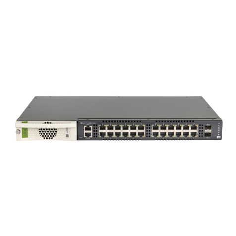
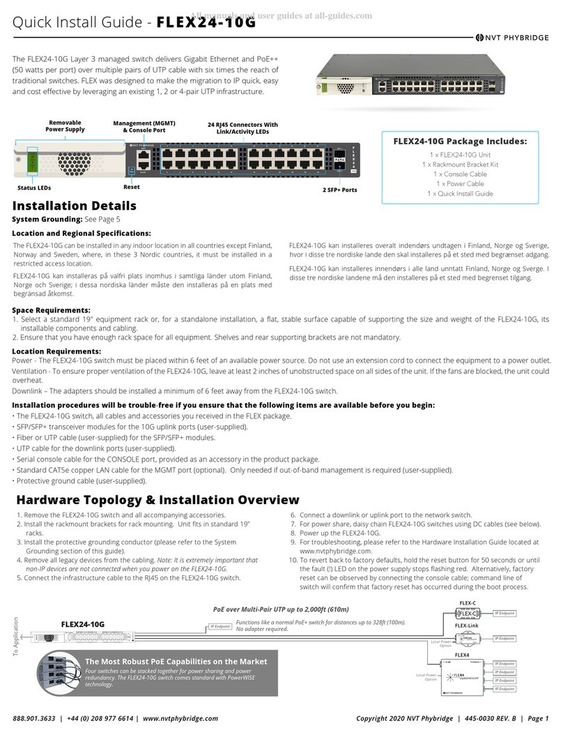
1. Select a standard 19" equipment rack or, for a standalone installation, a flat, stable surface capable of supporting the size and weight of the FLEX24, its installable
components and cabling.
2. Ensure that you have enough rack space for all equipment. Shelves and rear supporting brackets are not mandatory.
Location Requirements:
Power - The FLEX24 switch must be placed within 6 feet of an available power source. Do not use an extension cord to connect the equipment to a power outlet.
Ventilation - To ensure proper ventilation of the FLEX24, leave at least 2 inches of unobstructed space on all sides of the unit. If the fans are blocked, the unit could
overheat.
Downlink – The adapters should be installed a minimum of 6 feet away from the FLEX24 switch.
Installation procedures will be trouble‐free if you ensure that the following items are available before you begin:
• The FLEX24 switch, all cables and accessories you received in the FLEX package.
• SFP transceiver modules for the Gbic uplink trunks (user-supplied) if connecting over fiber.
• Fiber optic LAN cables for the Gbic uplink trunks (user-supplied) if connecting over fiber.
• Standard CAT5e copper LAN cables for the GbE uplink trunks (user‐supplied).
• UTP cable for the downlink ports (user-supplied).
• Serial console cable for the CONSOLE port, provided as an accessory in the product package.
• Standard CAT5e copper LAN cable for the MGMT port (optional). Only needed if out-of-band management is required (user‐supplied).
• Protective ground cable (user‐supplied).
POWER CAPABILITIES AND CONSIDERATIONS
FLEX24 switches come standard with a hot swappable PowerWise power supply for power/load sharing. The switch will support either an AC or DC power
source.
The switches are amongst the lowest power consuming switches in the industry.
For a redundant power configuration, daisy-chain multiple FLEX24 switches:
You can connect up to a maximum of 4 units for power/load sharing.
• Mount all FLEX24 switches in the same equipment rack, with no more than 1U space between any two units.
Note: You can daisy-chain the units together while they are up and running or power them up afterward.
• Facing the rear of the units, install the DC cables (available through Phybridge) as follows:
Note: To fit properly, the DC cable must be inserted into the DC input/output connector with its hairpin clip
on top.
• For the top unit, insert the first cable into the DC input connector on the left until it clicks into place. Bring the
other end of the cable down to the next unit, and connect to the DC output connector on the right.
• Continue in the same way for each pair of units, connecting the DC input (left) connector on the upper unit to
the DC output (right) connector on the lower unit.
Important: For the bottom unit, the last cable from the DC input (left) connector goes up to the DC output
(right) connector on the top unit. This is required to create a fully redundant ring.
Note: If you need to move a cable to to a different DC connector on the FLEX24, press the hairpin clip at the
top of the DC cable and pull the cable out.
CONFIGURING THE FLEX24 (2 METHODS)
Connecting to the Admin GUI
Default IP Address:
• MGMT = 192.168.1.1
• GBE1 & GBE2 = 192.168.100.1
Default User Name & Password:
• User Name: admin
• Password: admin
Steps to Change the IP Address:
1. Click on Ethernet menu option on the top bar.
2. Once Ethernet page is displayed select UPLINK
PORTS.
3. Type in new IP address in the IP Address section for IP
configuration.
4. Type in new Net Mask in the Net Mask section (e.g.
255.255.255.0).
5. Type in new IP address of the system default gateway
in the Default Gateway section.
6. Click Save Changes button to apply the modifications.
7. Refer to admin guide for more software details.
Connecting to FLEX24:
1. Change the IP address of your PC or Laptop to
192.168.1.2
2. Connect your Ethernet port on the PC or Laptop to the
MGMT port on the FLEX24.
3. Open a web browser that is up to date and type in/go
to http://192.168.1.1
4. Login is “admin” password is “admin” (without quotes)
5. You are now in the Admin GUI.
NOTE: Change IP addresses to avoid conflict.
(Ethernet/Uplink Ports)
Connecting to the Command Line Interface (CLI)
Accessibility:
• Console cable connected directly to the console port.
Console Port Serial Settings:
• 115200/8/N/1
Default User Name & Password:
• User Name: admin
• Password: admin
Steps to Change the IP Address:
1. Type in “pal-set-sys-ip GbE 192.168.9.1 255.255.255.0
192.168.9.255” Substitute the provided example IP
information for your own.
a. The usage is: pal-set-sys-ip GbE <IPADDRESS>
<NETMASK> <BROADCAST>
2. You will be prompted to confirm this information.
3. Refer to the CLI section of the administration guide for
more information.
Connect to the Console Port:
1. Connect the RJ45 end of the serial cable to the console
port of the FLEX24. Connect the serial end of the serial
cable to the serial port of your PC.
2. Configure your serial port to 115200/8/N/1.
3. Login is “admin”, password is ”admin” (without quotes)
4. You are now connected to the CLI via the console port.
Changing Management Port Default IP Address
The Mgmt IP default address of 192.168.1.1 may conflict with other FLEX24s. To prevent this from happening, you must change the IP address of the Mgmt Port to an IP which
will never be used on the network. For example, if your network belongs to the “192.168.X.X” subnet, change the Mgmt Port IP to “10.10.1.1”.
Steps to Change the Management Port IP Address:
1. Log into the unit via the serial console port (115200,8,N,1,None).
2. Type in “pal-set-sys-ip mgmt 10.10.1.1 255.255.255.0 10.10.1.255”
Substitute the provided example IP information for your own.
a. The usage is: pal-set-sys-ip mgmt <IPADDRESS> <NETMASK> <BROADCAST>
3. You will be prompted to confirm this information.
4. Refer to the CLI section of the administration guide for more information.
5. You are now connected to the CLI via the console port.
QUICK INSTALL GUIDE
IN
OUT
IN
OUT
IN
OUT
IN
OUT
IN
OUT
IN
OUT
