LED
USB
POWER
PSU
MB
SATA
USB
SATA
FAN 3
FAN 2
FAN 1
COMPONENT LIST
LISTA DE COMPONENTES
LISTE DES COMPOSANTS
KOMPONENTENLISTE
СПИСОК КОМПОНЕНТОВ
ELENCO DEI COMPONENTI
LISTA DE COMPONENTES
구성품 목록
部品リスト
零件表
零件表
A.
B.
C.
D.
E.
F.
G.
H.
I.
J.
K.
L.
Temperedglass thumb nut
Thumb screw 6-32 x 6mm
Special thumb screw 6-32 x 6mm
Hexagon screw 6-32 x 6mm
Screw 6-32 x 5mm
Screw M3 x 5mm
Screw KB5 x 10mm
Standoff 6-32 x 6.5+4mm
Standoff wrench
Cable tie
GPU stand
Breakout Cable
Temperedglass installation
Extension slots installation
Side panel, Front fan braket,SSD bracket
Power supply installation
Motherboard installation,3.5 hard drive installation
2.5 hard drive installation
Fan installation
Motherboard installation
Motherboard installation
Cable management
GPU installation
For Non-Intel Standard F_Panel Header Use
A.
B.
C.
D.
E.
F.
G.
H.
I.
J.
K.
L.
Pouce écrou
Vis à serrage à main 6-32 x 6 mm
Vis à serrage à main spéciale 6-32 x 6 mm
Vis hexagonale 6-32 x 6 mm
Vis 6-32 x 5 mm
Vis M3 x 5 mm
Vis KB5 x 10 mm
Entretoise 6-32 x 6,5 + 4 mm
Clé pour entretoise
Attache-câble
Support du GPU
Câble multi connexions
Mise en place du panneau en verre trempé
Plateau disque dur 2,5’’,installation des emplacements d'extension
Panneau latéral, Support d'alimentation électrique,Plateau disque dur
Installation de l'alimentation électrique
Installation de la carte mère,installation du disque dur 3,5’’
Installation du disque dur 2,5’’
Installation du ventilateur
Installation de la carte mère
Installation de la carte mère
Gestion du câblage
Installation du GPU
Pour le connecteur Front Panelde car tesmères non-intel
A.
B.
C.
D.
E.
F.
G.
H.
I.
J.
K.
L.
барашковая гайка
Винт с барашком 6-32 х 6 мм
Специальный винт с барашком 6-32 х 6 мм
Винт шестигранный 6-32 х 6 мм
Винт 6-32 х 5 мм
Винт M3 х 5 мм
Винт КВ5 х 10 мм
Стойка 6-32 х 6,5 + 4 мм
Гаечныйключ
Кабельный хомут:
Подставка для графического процессора
Кабель-разветвитель
Установка закаленного стекла
Установка лотка для жестких дисков 2,5'',разъемов расширения
Боковая панель, кронштейн для источника питания, лоток для жестких дисков
Установка источника питания
Установка материнскойплаты, установка жесткого диска 3,5''
Установка жесткогодиска 2,5''
Установка вентилятора
Установка материнскойплаты
Установка материнскойплаты
Организация кабельных систем
Установка графическогопроцессора
Для подключения фронтальной панели к материнским платам с разъёмами
не-Intel стандарта
A.
B.
C.
D.
E.
F.
G.
H.
I.
J.
K.
L.
엄지 손가락 너트
나비나사 6-32 x 6mm
특수 나비나사 6-32 x 6mm
육각나사 6-32 x 6mm
나사 6-32 x 5mm
나사 M3 x 5mm
나사 KB5 x 10mm
스탠드오프 6-32 x 6.5+4mm
스탠드오프 렌치
케이블 타이
GPU 스탠드
브레이크아웃 케이블
강화 유리 설치
2.5 하드 드라이브 트레이, 확장 슬롯 설치
사이드 패널, 전원공급장치 브래킷, HDD 트레이
전원공급장치 설치
마더보드 설치, 3.5 하드 드라이브 설치
2.5 하드 드라이브 설치
팬 설치
마더보드 설치
마더보드 설치
케이블 정리
GPU 설치
비 인텔 표준 메인보드 F-패널(전면 패널) 헤더 용
A.
B.
C.
D.
E.
F.
G.
H.
I.
J.
K.
L.
強化ガラスつまみナット
ツマミネジ6-32 x 6mm
特製ツマミネジ6-32 x 6mm
6角ネジ6-32 x 6mm
ネジ6-32 x 5mm
ネジ M3 x 5mm
ネジKB5 x 10mm
スタンドオフ6-32 x 6.5+4mm
スタンドオフ レンチ
ケーブルタイ
GPU スタンド
ブレークアウトケーブル
強化ガラス取り付け
2.5HDDトレイ、拡張スロット装着用
サイドパネル、電源ブラケット、HDDトレイ固定用
電源装着用
マザーボード装着、3.5HDD装着用
2.5HDD装着
ファン装着用
マザーボード装着用
マザーボード装着用
ケーブル整理用
GPU 取り付け
MBのF-PanelヘッダがIntel標準ではない場合
A.
B.
C.
D.
E.
F.
G.
H.
I.
J.
K.
L.
钢化玻璃指旋螺母
指旋螺丝 6-32 x 6mm
特制指旋螺丝
六角螺丝 6-32 x 6mm
螺丝 6-32 x 5mm
螺丝 M3 x 5mm
螺丝 KB5 x 10mm
脚柱 6-32 x 6.5+4mm
脚柱套筒板手
束线带
GPU 支架
分接线
钢化玻璃安装
2.5 硬碟托盘, 扩充槽安装
侧板, 电源支架
安装电源
3.5 硬盘安装, 主板安装
2.5 硬盘安装
安装风扇
主板安装
主板安裝
线缆管理
GPU 安装
用于非英特尔标准主板前版接口
A.
B.
C.
D.
E.
F.
G.
H.
I.
J.
K.
L.
鋼化玻璃手轉螺母
指旋螺絲 6-32 x 6mm
特製指旋螺絲
六角螺絲 6-32 x 6mm
螺絲 6-32 x 5mm
螺絲 M3 x 5mm
螺絲 KB5 x 10mm
腳柱 6-32 x 6.5+4mm
腳柱套筒板手
束線帶
GPU 底座
分接線
強化玻璃安裝
2.5 硬碟托盤, 擴充槽安裝
側板, 電源支架
安裝電源
3.5 硬碟安装, 主機板安装
2.5 硬碟安装
安裝風扇
主板安装
主板安裝
線纜管理
GPU 安裝
用於非英特爾標準主板前版接頭
A.
B.
C.
D.
E.
F.
G.
H.
I.
J.
K.
L.
Flügelmutter
Rändelschraube 6 – 32 x 6 mm
Spezielle Rändelschraube 6 – 32 x 6 mm
Sechskantschraube 6 – 32 x 6 mm
Schraube 6 – 32 x 5 mm
Schraube M3 x 5 mm
Schraube KB5 x 10 mm
Abstandhalter 6 – 32 x 6,5 + 4 mm
Abstandhalter-Schlüssel
Kabelbinder
GPU-Ständer
Kabelpeitsche
Installation des Hartglasfensters
2,5-Zoll-Festplatteneinschub,Installation von Erweiterungssteckplätzen
Seitenblende,Netzteilhalterung, Festplattenfach
Netzteilinstallation
Motherboard-Installation,3,5-Zoll-Festplatteninstallation
2,5-Zoll-Festplatteninstallation
Lüfterinstallation
Motherboard-Installation
Motherboard-Installation
Kabelverwaltung
GPU-Installation
Front Panel Header für alle gängigen nicht-IntelMainboards
A.
B.
C.
D.
E.
F.
G.
H.
I.
J.
K.
L.
Dado pollice
Viti a testa zigrinata 6-32 x 6 mm
Vite a testa zigrinata speciale 6-32 x 6 mm
Vite esagonale 6-32 x 6 mm
Vite 6-32 x 5 mm
Vite M3 x 5 mm
Vite KB5 x 10 mm
Distanziatore 6-32 x 6,5 + 4 mm
Chiave per distanziatori
Fascetta per cavi
Supporto GPU
Cavo multiconnessione
Installazione vetro temperato
2.5 Cassetto HDD,installazione alloggi d’espansione
Pannello laterale,staffa alimentatore, cassetto HDD
Installazione dell’alimentatore
Installazione della scheda madre,installazione HDD 3.5”
Installazione HDD 2.5”
Installazione della ventola
Installazione della scheda madre
Installazione della scheda madre
Gestione dei cavi
Installazione della GPU
Connettore F-Panel per Mainboard non Intel
A.
B.
C.
D.
E.
F.
G.
H.
I.
J.
K.
L.
Porca de polegar
Parafusos borboleta 6-32 x 6 mm
Parafusos de borboleta 6-32 x 6 mm
Parafusos hexagonal 6-32 x 6 mm
Parafusos 6-32 x 5 mm
Parafusos M3 x 5 mm
Parafusos KB5 x 10 mm
Separadores 6-32 x 6,5+4 mm
Chave para separador
Braçadeira para cabos
Suporte da GPU
Cabo divisor
Instalação do vidro temperado
tabuleiro da unidade de 2,5",instalação das ranhuras de extensão
painel lateral, suporte da fontede alimentação, tabuleiro de HDD
instalação da fonte de alimentação
instalação da placa principal, instalação da unidade de 3,5"
instalação da unidade de 2,5"
instalação da ventoinha
instalação da placa principal
instalação da placa principal
Gestão de cabos
Instalação da GPU
Para ligação do painel frontal (F-Panel) em placa-mãe padrãonão-Intel
A.
B.
C.
D.
E.
F.
G.
H.
I.
J.
K.
L.
Tuercade mariposa
Tornillode apriete manual de 6-32 x 6 mm
Tornillode apriete manual especial
de 6-32 x 6 mm
Tornillohexagonal de 6-32 x 6 mm
Tornillode 6-32 x 5 mm
TornilloM3 x 5mm
TornilloKB5 x 10 mm
Separador 6-32 x 6,5 +4 mm
Llave para separadores
Brida para cables
Soporte de la GPU
Cable multiconector
Instalación de vidrio templado
bandeja de unidad de disco duro de 2,5" e instalación de ranuras de extensión
panel lateral,sopor tede fuente de alimentación y bandeja para unidad
de disco duro
instalación de la fuente de alimentación
instalación de la placa base e instalación de la unidad de disco duro de 3,5"
instalación de la unidad de disco duro de 2,5"
instalación del ventilador
instalación de la placa base
instalación de la placa base
Administración de los cables
Instalación de la GPU
Para panel frontal de placas base no Intel.
x7
Installed x7
Accessory Box x0
CSpecial thumb screw 6-32 x 6mm
x10
Installed x4
Accessory Box x6
DHexagon screw 6-32 x 6mm
x8
Installed x0
Accessory Box x8
EScrew 6-32 x 5mm
x16
Installed x0
Accessory Box x16
FScrew M3 x 5mm
A
x4
Installed x4
Accessory Box x0
Tempered glass thumb nut
x16
Installed x8
Accessory Box x8
GScrew KB5 x 10mm
x4
Installed x4
Accessory Box x0
HStandoff 6-32 x 6.5+4mm
x1
Installed x0
Accessory Box x1
IStandoff wrench
x10
Installed x0
Accessory Box x10
JCable tie
x1
Installed x0
Accessory Box x1
KGPU Stand
x4
Installed x4
Accessory Box x0
BThumb screw 6-32 x 6mm
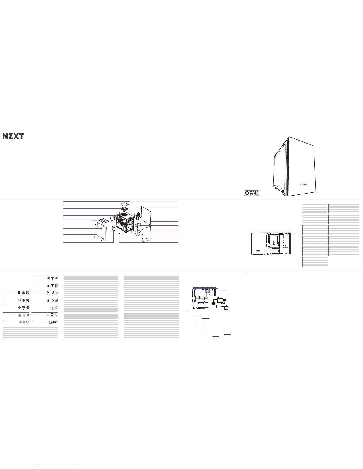
MINI-ITX CASE
H200i / H200
CLEARANCES AND SPECIFICATIONS
MEDIDAS Y ESPECIFICACIONES
DÉGAGEMENTS ET SPÉCIFICATIONS
ABSTÄNDE UND TECHNISCHE DATEN
ТЕХНИЧЕСКИЕ ХАРАКТЕРИСТИКИ И ЗАЗОРЫ
SPAZI NECESSARI E SPECIFICHE
DIMENSÕES E ESPECIFICAÇÕES
간격과 규격
空間と仕様
间距与规格
間距與規格
主板支援:
2.5’’SSD支援
3.5’’HDD支援
擴充槽
GPU 間距
線纜管理
CPU 散熱器間距
前面散熱氣
Mini-ITX
3+1
1
2
325mm
15.9mm
165mm
85mm
主板支持:
2.5’’SSD支持
3.5’’HDD支持
扩充槽
GPU 间距
线缆管理
CPU 散热器间距
前面散热气
Mini-ITX
3+1
1
2
325mm
15.9mm
165mm
85mm
マザーボードサポート
2.5’’SSDサポート
3.5’’HDDサポート
エクスパンションスロット
GPUクリアランス
ケーブルの管理
CPUクーラークリアランス
フロントラジエーター
Mini-ITX
3+1
1
2
325mm
15.9mm
165mm
85mm
Поддержка материнской платы
для твердотельных накопителей 2,5"
для жестких дисков 3,5"
Разъемы расширения
Зазор для графического процессора
Организация кабельных систем
Кулер процессора
Передний радиатор
Mini-ITX
3+1
1
2
325mm
15.9mm
165mm
85mm
Placa-principais suportadas
SSD de 2,5"
HDD de 3,5”
Ranhuras de expansão
Folga para a GPU
Gestão de cabos
Dissipador de CPU
Radiador frontal
Mini-ITX
3+1
1
2
325mm
15.9mm
165mm
85mm
마더보드 지원
2.5" SSD
3.5" HDD
확장 슬롯
GPU 간격
케이블 정리
CPU 쿨러
앞쪽 라디에이터
Mini-ITX
3+1
1
2
325mm
15.9mm
165mm
85mm
Cartes mère prises en charge
SSD 2,5’’
Disques durs 3,5’’
Baies d'extension
Longueur du GPU
Gestion du câblage
Radiateur du processeur
Radiateur avant
Mini-ITX
3+1
1
2
325mm
15.9mm
165mm
85mm
Placas base admitidas
Unidad de estado sólido de 2,5’’
Unidad de disco duro de 3,5”
Ranuras de expansión
Distancia de seguridad para GPU
Administración de los cables
Disipador de la CPU
Radiador frontal
Mini-ITX
3+1
1
2
325mm
15.9mm
165mm
85mm
Motherboard Support
2.5” SSD Support
3.5” HDD Support
Expansion Slots
GPU Clearance
Cable Management
CPU Cooler Clearance
Front Radiator
Mini-ITX
3+1
1
2
325mm
15.9mm
165mm
85mm
EXPLODED VIEW
VISTA EXPLOSIONADA
VUE EN ÉCLATÉ
EXPLOSIONSDARSTELLUNG
ТРЕХМЕРНОЕ ПРЕДСТАВЛЕНИЕ ДЕТАЛЕЙ
VEDUTA IN ESPLOSO
VISTA EXPLODIDA
확대도
展開図
部件分解图
部件分解圖
1.
2.
3.
4.
5.
6.
7.
8.
9.
10.
11.
12.
13.
14.
15.
16.
17.
18.
19.
섀시
상단 필터
상단 배기팬
상단 RGB LED 스트립
후면 배기팬
SFX PSU 브래킷
PSU 먼지 필터
좌측 강화 유리 패널
좌측 강화 유리 사이드 패널
SSD 트레이
전면 I/O
SSD 브래킷
스마트 장치 (H200i)
우측 메탈 패널
전면 먼지 필터
전면 베젤
전면 쿨러 브래킷
케이블 정리 바
GPU 스탠드
1.
2.
3.
4.
5.
6.
7.
8.
9.
10.
11.
12.
13.
14.
15.
16.
17.
18.
19.
シャーシ
上部フィルタ
トップ排出ファン
トップ RGB LED ストリップ
リア排出ファン
SFX PSU ブラケット
PSU ダストフィルター
左強化ガラスパネル
左サイド強化ガラスパネル
SSDトレイ
フロント I/O
SSD ブラケット
スマートデバイス (H200i)
右サイド金属パネル
フロントダストフィルター
フロントベゼル
フロントクーラーブラケット
クリーン保持具
GPU スタンド
1.
2.
3.
4.
5.
6.
7.
8.
9.
10.
11.
12.
13.
14.
15.
16.
17.
18.
19.
机箱
上部滤网
顶部排气扇
顶部 RGB LED 灯带
后排气扇
SFX PSU 支架
PSU 防尘过滤器
钢化玻璃指旋螺母
左侧钢化玻璃板
硬盘架
前端 I/O
SSD 支架
智能设备 (H200i)
右侧金属板
前端灰尘过滤器
前挡板
前端冷却器支架
理线档板
GPU 支架
1.
2.
3.
4.
5.
6.
7.
8.
9.
10.
11.
12.
13.
14.
15.
16.
17.
18.
19.
機殼
上部濾網
頂部排風風扇
頂部 RGB LED 燈條
後方排風風扇
SFX 電源供應器架
電源供應器防塵濾網
鋼化玻璃手轉螺母
左側強化玻璃面板
硬盤架
前方 I/O
SSD 架
智慧裝置 (H200i)
右側金屬面板
前方防塵過濾網
前面板
前方散熱器架
理線檔板
GPU 底座
Chasis
Filtro superior
Ventilador de escape superior
Tira LED RGB superior
Ventilador de escape trasero
Soporte de la PSU SFX
Filtro de polvo de la PSU
Panel de cristal templado izquierdo
Panel de vidrio templado lateral izquierdo
Bandeja unidad de estado sólido
E/S frontal
Soporte para SSD
Dispositivo inteligente (H200i)
Panel metálico derecho
Filtro de polvo frontal
Bisel frontal
Soporte del refrigerador frontal
Barra de limpieza
Soporte de la GPU
1.
2.
3.
4.
5.
6.
7.
8.
9.
10.
11.
12.
13.
14.
15.
16.
1 7.
18.
19.
SMART DEVICE (H200i)
DISPOSITIVO INTELIGENTE
APPAREIL INTELLIGENT
SMART DEVICE
ИНТЕЛЛЕКТУАЛЬНОЕ УСТРОЙСТВО
DISPOSITIVO INTELLIGENTE
DISPOSITIVO INTELIGENTE
스마트 장치
スマートデバイス
智能设备
智慧裝置
The Smart Device connects to your PC via a single internal USB 2.0 connector. Toenable control of the Smart Device, download
and install CAM from camwebapp.com.
FANCONNECTORS - Three Fan connectors for three channels.To attach additional fans, use the included fan splitters.
Note:The first fan connector with 4 pins on the fan splitter will be the primary fan. Do not mix PWM or 3-pin fans.
Note:To most effectively use CAM’ssmart Adaptive Noise Reduction, you should connect your CPU fan to the Smart Device.If you
choose to do this,you will need to disable the CPU Fan warning in your motherboard’s BIOS settings.
RGB LED CONNECTOR- One LED strip is integrated inside the case. Connect additional HUE+ LED strips via the end connector located
on the bottom LED strip.To connect Aer RGB,connect directly to the RGB LED connector.
POWER CONNECTOR- Connect to the power supply to power on the smart device, fans,and LED strips.
Note:Do not connect while PC is powered on.
CONECTORESDE VENTILADOR - Tres conectores de ventilador para tres canales.Para conectar ventiladores adicionales, utiliza los
cables bifurcadores paraventilador incluidos.
Nota:El primer conector de ventilador con 4 patillas del cable bifurcador para ventilador será el ventilador principal. No mezcle
ventiladores PWM y de 3 patillas.
Nota:Para utilizar la reducción de ruido adaptativa inteligente de CAM de la forma más eficaz, debes conectar el ventilador de la CPU al
dispositivo inteligente.Si decides hacerlo, deberás desactivar la advertencia del ventilador de la CPU en la configuración de la BIOS de
la placa base.
CONECTORLED RGB - Hay una tira de LED integrada en el interior de la caja. Conecta tiras LED HUE+ adicionales mediante el conector
final ubicado en la tira de LED inferior.Para conectar Aer RGB, conéctalosdirectamente al conector LED RGB.
CONECTORDE ALIMENTACIÓN - Conéctalo a la fuente de alimentación para alimentar el dispositivo inteligente,los ventiladores y las
tiras de LED.
Nota:No lo conectes mientras el PC esté encendido.
CONNECTEURS DE VENTILATEUR- Trois connecteurs de ventilateur pour troiscanaux. Pour installer d'autres ventilateurs, utilisez les
répartiteurs fournis.
Remarque:le ventilateur branché au premier connecteur de ventilateur à 4broches du répartiteur de ventilateur est le ventilateur
principal. Ne pas brancherles ventilateurs PWM et les modèles à 3broches sur le même canal.
Remarque:Pour profiter au maximum du système de réduction intelligente de bruit du CAM,vous devez relier le ventilateur de votre
processeur au Smart Device.Dans ce cas, vous devrez désactiver l'avertissement d'absence de ventilateur du processeur dans les
paramètres BIOS de votre carte mère.
CONNECTEUR LED RGB - Une bande LED est intégrée auboîtier. Connectez d'autres bandes LED HUE+ via le connecteur situé sur la
bande LED inférieure.Pour connecter Aer RGB, branchez directement au connecteur LED RGB.
CONNECTEUR D'ALIMENTATION - Branchez à l'alimentation pour alimenter le Smart Device, les ventilateurset les bandes LED.
Remarque:ne pas brancher lorsque l'ordinateur est sous tension.
LÜFTERANSCHLÜSSE- Drei Lüfteranschlüsse für drei Kanäle. Weitere Lüfterkönnen über die im Lieferumfang enthaltenen
Lüfter-Splitter angeschlossenwerden.
Hinweis:Der erste 4-polige Lüfteranschluss am Lüfter-Splitter ist der primäre Lüfter- PWM und 3-polige Lüfter dürfen nichtüber
denselben Kanal kombiniert werden.
Hinweis:Für den effizienten Einsatz der intelligenten Adaptive Noise Reduction am CAM sollten Sie den CPU-Lüfter mit dem Smart
Device verbinden.Sie müssen dazu die CPU-Lüfterwarnung in den BIOS-Einstellungen des Mainboards deaktivieren.
RGB-LED-STECKVERBINDER - Ein LED-Streifen ist in das Gehäuseintegriert .Weitere HUE+ LED-Streifen können über den
Endverbinder am unteren LED-Streifen angeschlossenwerden. Weitere Aer RGB können direkt über den RGB-LED-Steckverbinder
angeschlossen werden.
STROMANSCHLUSS- Schließen Sie das Netzteil an, um das Smart Device, die Lüfter und die LED-Streifen einzuschalten.
Hinweis:Nicht anschließen, während der PC eingeschaltet ist.
CONNETTORI VENTOLE - Treconnettori ventole per tre canali. Per fissare le ventole aggiuntive,utilizzare gli splitter ventole inclusi.
Nota:il primo connettore ventole con 4 pin sullo splitter ventola sarà la ventola principale. Non mischiareventole PWM e ventole a 3 pin
nello stesso canale.
Nota:per utilizzare in maniera più efficace la riduzione del rumore adattiva di CAM, si consiglia di connettere la ventola CPU al
dispositivo intelligente.Se si sceglie questa opzione, è necessario disattivare l'avviso relativo alla ventola CPU nelle impostazioni BIOS
della scheda madre.
CONNETTORE LED RGB - Una striscia LED è integrata nel case.Collegare i nastri LED HUE+ aggiuntivi al connettore finale posizionato
sul nastro LED inferiore.Per collegare la ventola Aer RGB, collegarla direttamente al connettoreLED RGB.
CONNETTORE DI ALIMENTAZIONE- Collegare l'alimentazione per accendere il dispositivo intelligente, le ventole e i nastri LED.
Nota:non effettuare il collegamento se il PC è acceso.
Le Smart Device se connecte à votre PC via un seul port USB2.0 interne.Pour activer le Smart Device, veuillez télécharger CAM
sur camwebapp.com.
Das Smart Device wird über den internen USB2.0-Anschluss mit IhremPC verbunden. Um die Steuerung des Smart Device zu
aktivieren, einfachCAM über camwebapp.com herunterladen und installieren.
Il dispositivo intelligente si collega al PC tramite un connettoreUSB 2.0 singolo interno. Per abilitare il controllo del dispositivo,
scaricare e installare CAM da camwebapp.com.
O dispositivo inteligente se conecta a seu computador por um conector USB 2.0 internosimples. Para habilitar o controle do
dispositivo inteligente,baixe e instale o CAM em camwebapp.com.
이 스마트 장치는 단일 내부 USB 2.0 커넥터를 통해 PC에 연결됩니다. 스마트 장치의 제어 기능을 사용하려면 camwebapp.com에서 CAM을
다운로드하고 설치하십시오.
スマートデバイスは、内蔵 USB 2.0 コネクタ 1 つで PC に接続します。スマートデバイスを制御するには、camwebapp.com から CAM をダ
ウンロードしてインストールしてください。
智能设备通过单个 USB 2.0 接口连接到您的计算机。要想控制智能设备,请从 camwebapp.com 下载并安装 CAM。
智慧裝置透過一個內部的 USB 2.0 連接器連接至電腦。若要控制智慧裝置,請至 camwebapp.com 下載並安裝 CAM。
Интеллектуальное устройство подключается к ПК через внутренний портUSB2.0 Для управления интеллектуальным устройством
загрузите и установитеCAM с сайта camwebapp.com.
El dispositivo inteligente se conecta a tu PC mediante un único conector USB 2.0interno. Para activar el control del dispositivo
inteligente,descarga e instala CAM desde camwebapp.com.
SMART DEVICE
PORTS CONECTORESDE VENTOINHA - Três conectoresde ventoinhas para três canais. Para conectar ventoinha adicionais, utilizeos divisores
para ventoinha incluídos.
Nota:O primeiro conector de ventoinha com 4 pinos no divisor para ventoinha será a ventoinha primária. Não misture ventoinhas PWM
ou 3 pinos.
Nota:Para usar a redução adaptável de ruído inteligente da CAM, você deve conectar a ventoinha da CPU ao dispositivo inteligente.
Se você escolher fazer isso,será necessário desabilitar o alerta da ventoinha da CPU nas configurações BIOS da placa-mãe.
CONECTORRGB DE LED - Uma tira de LED é intregrada à parte interna do gabinete. Conecte as faixas de LED HUE+ adicionais pelo
conector final localizado na parte inferior da faixa de LED.Para conectar o Aer RGB, conecte diretamente o conector LED RGB.
CONECTORDE ALIMENTAÇÃO - Conecte a fonte de alimentação à alimentação do dispositivo inteligente,às ventoinhas e às faixas de
LED.
Nota:Não conecte enquanto o computador estiver ligado.
Разъемывентиляторов - Три разъема вентиляторов для трех каналов. Чтобы присоединить дополнительные вентиляторы,воспользуйтесь
разветвительными кабелями для вентиляторов (в комплекте).
Примечание. Первый 4-контактный разъем разветвительногокабеля предназначен для основного вентилятора. Не используйте PWM и
3-контактные вентиляторына одном кана ле.
Примечание. Для максимально эффективного использования интеллектуальной функции адаптивного шумоподавления CAM необходимо
подключить вентилятор ЦП к интеллектуальному устройству.Если вы решите это сделать, необходимо будет отключить предупреждение
вентилятора ЦП в настройках BIOS материнскойплаты.
Светодиодныйразъем (RGB) - Одна светодиодная лента встроена внутрь корпуса. Подсоедините дополнительные светодиодныеленты HUE+ к
разъему,расположенному на конце светодиодной ленты. Чтобы подключить Aer RGB, подсоединитеего напрямую к светодиодному разъему (RGB).
Разъемпитания - Чтобы включить интеллектуальное устройство, вентиляторы и светодиодные ленты, подключите их к блоку питания.
Примечание. Не подключайте, если ПК включен.
팬 커넥터 - 3개 채널을 탑재했으며, 각 채널별로 3개의 팬 커넥터가 있습니다. 다른 팬을 추가로 설치하려면 포함된 팬 스플리터를 사용하십시오.
참고: 팬 스플리터에 핀 4개가 있는 첫 번째 팬 커넥터가 기본 팬입니다. PWM과 3핀 팬을 혼용하지 마십시오.
참고: CAM의 스마트한 적응형 노이즈 감소 기능을 효율적으로 사용하려면 CPU 팬을 스마트 장치에 연결해야 합니다. CPU 팬을 스마트 장치에 연결할
경우, 마더보드의 BIOS 설정에서 CPU 팬 경고 기능을 비활성화해야 할 수도 있습니다.
RGB LED 커넥터 - LED 스트립 1개가 케이스 내부에 내장되어 있습니다. 하부 LED 스트립에 위치한 엔드 커넥터를 통해 추가 HUE+ LED 스트립을 연
결하십시오. Aer RGB를 연결하려면 RGB LED 커넥터에 직접 연결하십시오.
전원 커넥터 - 전원 공급 장치에 연결하여 스마트 장치, 팬, LED 스트림에 전원을 공급합니다.
참고: PC 전원이 켜져 있는 동안에는 연결하지 마십시오.
ファンコネクタ - 3 つのチャネル用に 3 つのファンコネクタがあります。追加のファンを取り付けるには、付属のファンスプリッタを使用してください。
注:ファンスプリッタの最初の 4 ピンファンコネクタがプライマリファンになります。同じチャネルに PWM ファンと 3 ピンファンを混在させないでください。
注:CAM のスマート自動ノイズ低減機能を最も効果的に使用するには、CPU ファンをスマートデバイスに接続する必要があります。接続する場合は、マザーボ
ードの BIOS 設定で CPU ファンの警告を無効にする必要があります。
RGB LED コネクタ - 1 本の LED ストリップがケース内に統合されています。追加の HUE+ LED ストリップは、ボトム LED ストリップにあるエンドコ
ネクタで接続してください。Aer RGB を接続するには、RGB LED コネクタに直接接続してください。
電源コネクタ - スマートデバイス、ファン、LED ストリップに電源を供給するには、電源に接続してください。
注:PC の電源がオンの間は接続しないでください。
风扇接头 - 三个风扇接头,用于三个通道。要连接额外的风扇,请使用随附的风扇转接线。
注:风扇分频线上第一个 4 针风扇接头将用于主风扇。在同一通道请勿混淆 PWM 或 3 针风扇。
注:为了更有效地使用 CAM 的智能自适应降噪功能,您应该将 CPU 风扇连接到智能设备上。如果选择这样做,您应该在主板的 BIOS 设置中禁用 CPU 风
扇警告。
RGB LED 接头- 一条 LED 灯带已集成在机箱内。请通过底部 LED 灯带上的端接器连接额外的 HUE+ LED 灯带。要连接 Aer RGB,请直接连接至 RGB LED 接头。
电源接头 - 连接到电源,让智能设备、风扇和 LED 灯带通电。
注:请勿在计算机通电状态下进行连接。
風扇連接器 - 三個風扇連接器供三個通道使用。若要連接額外的風扇,請使用隨附的風扇分線器。
備註︰風扇分線器上的第一個 4 針腳風扇連接器將是主要風扇。請勿在同一個通道中混用 PWM 或 3 針腳風扇。
備註︰若要以最有效的方式使用 CAM 的自主適應降噪功能,您應將 CPU 風扇連接到智慧型裝置。若選擇這樣做,您必須停用主機板 BIOS 設定中的 CPU
風扇警告。
RGB LED 接頭 - 機殼內建一條 LED 燈條。透過底部 LED 燈條的端點接頭,即可連接額外的 HUE+ LED 燈條。若要連接 Aer RGB,請直接連接至
RGB LED 接頭。
電源連接器 - 連接至電源供應器,為智慧裝置、風扇及 LED 燈條供電和啟用。
備註︰電腦電源開啟時,請勿連接。
Motherboard-Unterstützung
2,5-Zoll-SSD
3,5-Zoll-Festplatte
Erweiterungssteckplätze
GPU-Abstand
Kabelverwaltung
CPU-Kühler
Vorderer Kühlkörper
Mini-ITX
3+1
1
2
325mm
15.9mm
165mm
85mm
Scheda madre supportata
SDD 2.5”
HDD 3.5”
Alloggi d’espansione
Spazio necessario alla GPU
Gestione dei cavi
Dispersore di calore CPU
Radiatore frontale
Mini-ITX
3+1
1
2
325mm
15.9mm
165mm
85mm
210MM 372MM
349MM
Châssis
Filtre à poussière du haut
Ventilateur en extraction du haut
Bande LED RVB du dessus
Ventilateur d'échappement arrière
Support du bloc d'alimentation SFX
Filtre à poussière du bloc d'alimentation
Vis à serrage à main pour le panneau en verre trempé
Panneau latéral gauche en verre trempé
Plateau SSD
E/S avant
Support du SSD
Smart Device (H200i)
Panneau métallique droit
Filtre à poussière avant
Cache avant
Support du dissipateur avant
Barre pour la gestion des câbles
Support du GPU
1.
2.
3.
4.
5.
6.
7.
8.
9.
10.
11.
12.
13.
14.
15.
16.
1 7.
18.
19.
Gehäuse
TopFilter
Lüfter für Luftauslass an Oberseite
RGB-LED-Streifen an Oberseite
Lüfter für Luftauslass an Rückseite
SFX-Netzteilhalterung
Netzteil-Staubfilter
Linke Hartglasblende
Hartglasfenster links
SSD-Fach
E/A an der Vorderseite
SSD-Halterung
Smart Device (H200i)
Seitliche Abdeckung rechts aus Metall
Staubfilter an Vorderseite
Einfassung an Vorderseite
Kühlerhalterung an Vorderseite
Reinigungsleiste
GPU-Ständer
1.
2.
3.
4.
5.
6.
7.
8.
9.
10.
11.
12.
13.
14.
15.
16.
1 7.
18.
19.
Chassis
Filtro superiore
Ventola di scarico superiore
Striscia LED RGB superiore
Ventola di scarico posteriore
Staffa alimentatore SFX
Filtro polvere alimentatore
Pannello laterale sinistro di vetrotemperato
Pannello laterale sinistro in vetrotemperato
Cassetto SDD
I/O anteriore
Staffa SSD
Dispositivo intelligente (H200i)
Pannello destro in metallo
Filtro polvere anteriore
Smussatura anteriore
Staffa raffreddamento anteriore
Barra di gestione dei cavi
Supporto GPU
1.
2.
3.
4.
5.
6.
7.
8.
9.
10.
11.
12.
13.
14.
15.
16.
1 7.
18.
19.
Chassi
Filtro de topo
Ventoinha de exaustão da parte superior
Tira de LED RGB da parte superior
Ventoinha de exaustão traseira
Suporte do PSU SFX
Filtro de pó do PSU
Painel esquerdo em vidro temperado
Vidro temperado do painel lateral esquerdo
Tabuleirode SSD
E/S frontal
Suporte do SSD
Dispositivo inteligente (H200i)
Painel de metal direito
Filtro de pó frontal
Moldura frontal
Suporte da ventoinha frontal
Barra de limpeza
Suporte da GPU
1.
2.
3.
4.
5.
6.
7.
8.
9.
10.
11.
12.
13.
14.
15.
16.
1 7.
18.
19.
Корпус
Верхний фильтр
Верхний вытяжной вентилятор
Верхняя светодиодная лента RGB
Задний вытяжной вентилятор
Кронштейн блока питания SFX
Пылевой фильтр блока питания
Левая панель из закаленного стекла
Левая боковая панель из закаленного стекла
Лоток для твердотельных накопителей
Разъемы спереди
Крепление SSD-накопителя
Интеллектуальное устройство (H200i)
Правая металлическая панель
Передний пылевой фильтр
Передняя рамка
Кронштейн передней системы охлаждения
Панель Clean sweep
Подставка для графического процессора
1.
2.
3.
4.
5.
6.
7.
8.
9.
10.
11.
12.
13.
14.
15.
16.
17.
18.
19.
x1
Installed x0
Accessory Box x1
LBreakout Cable
LED CONNECTOR
4
TOP RGB LED STRIP
18
CABLE BAR
19
GPU STAND
17
FRONT COOLER BRACKET
11
FRONT I/O
12
SSD BRACKET
13
SMART DEVICE (H200i)
14
RIGHT METAL PANEL
15
FRONT DUST FILTER
16
FRONT BEZEL
5
REAR EXHAUST FAN
6
SFX PSU BRACKET
7
PSU DUST FILTER
8
TEMPERED GLASS THUMB SCREW
9
LEFT TEMPERED GLASS SIDE PANEL
10
SSD TRAY
1
CHASSIS
2
TOP DUST FILTER
3
TOP EXHAUST FAN


 user manual")


