O3Zone OZ-1-A Assembly instructions

Ozone
Generator
Complete Kit Instructions
Installation, Programming, and Maintenance
Instructions for the O3Zone Generator
O
Z
O
N
E
G
E
N
E
R
A
T
O
R
O
Z
O
N
E
G
E
N
E
R
A
T
O
R

O3zone Generator Kit Instructions
2
Table of Contents
How It Works.......................................................................................3
Applications ..............................................................................3
Parts ..........................................................................................4
Installation Instructions.....................................................................5
Programming Procedures..................................................................8
Maintenance Instructions ..................................................................9
Check Ozone History ................................................................9
Adjust the Potentiometer.........................................................10
Replace the Cell ........................................................................12
Replace the Ozone Check Valve and Injector..........................13
Board Replacement............................................................................14
Maintenance Log ................................................................................15

3
OZONE GENERATOR KIT
Model No. oz-1-a
The Ozone Generator Kit is an optional system designed exclusively for use on air filtration
units. The generator, when installed and operated correctly, will assist in keeping your
filtration unit and media clean and functional without harmful chemical byproducts.
The generator works automatically during regeneration periods and requires very little
maintenance.
How it Works:
During regeneration, air filters recharge the top portion of the media tank with air. This
recharged air oxidizes contaminants in the water, allowing them to be filtered out through
the media below.
The Ozone Generator activates during the air-draw cycle of regeneration. As air is being
drawn into the tank, it passes through an electrical field created by the ozone generator
which converts normal oxygen (O2) to ozone (O3).The generated ozone is then drawn into
the tank which helps clean the unit of nuisance, slime producing bacteria. The ozone
generator will automatically turn itself o aer regeneration.
While producing ozone, the unit will measure and record the electrical amperage
consumed by the generator itself. The alarm feature, if turned on (default is o), will enter
into alarm status if a low amperage situation occurs for three consecutive regenerations.
This will be indicated by an alarm and the control valve will read “Service Ozone.” This
indicates the ozone generator is not operating correctly and may need to be adjusted (See
page 9 for more information on maintenance and troubleshooting)
Applications:
The Ozone Generator kit is compatible with filtration units using the following medias:
• Turbidex
• Catalytic Carbon
• Greensand Plus
•GST/Calcite
Warning: Do not install kit on an air filtration system that utilizes birm.

O3zone Generator Kit Instructions
4
Parts:
Prior to installation, confirm that the parts below are included with the kit. Some
components may arrive pre-installed. For replacement parts, contact Water-Right customer
service.
Item # Part # Description Qty
1 OZ1-A Ozone Kit Assembly with Replacement Board 1
1 OZ1-A-99 Ozone Kit Assembly with No Replacement Board 1
1 OZ1-CASE Enclosure Top, Bottom, and Clip 1
2 33217-WRP3 Replacement Cell 1
3 CH4642WR-A Air Draw Elbow/Check Valve 1
4 CJCPG-6PBLK 3/8” Compression Nut 1
1
2
3
4

5
Installation Instructions
Prior to installing the ozone generator, ensure that you have all of the required parts listed
on page 1. Some parts, such as the mounting clip, may have been factory assembled or pre-
installed. No tools are required to install the ozone generator or any of its components.
step 1: Position mounting clip over the
injector cap and press down until the clip
clicks into place over the cap. Ensure that
the sliding bracket on the clip is facing
away from the controller body.
Note: Pull up on the large tab to unlock
and remove the clip from the injector
cap.
step 2: Mount ozone generator box by
sliding it onto the mounting clip.
step 3: Install nut, clear ferrule, and
black ferrule on the tube connected to the
generator box.
Note: Parts must be installed on the
tube in the orientation shown above.
Removing stiener from end of tube may
aid in installation of ferrules. Be sure
to re-install stiener in the end of tube
when finished.
Nut Clear Ferrule
Black Ferrule
step 4: Remove and set aside the
existing air-draw elbow by pulling out the
red clip and liing up on the elbow.
step 5: Install the new air-draw elbow
by pushing it down into the port and
inserting the red clip until it clicks.

O3zone Generator Kit Instructions
6
Installation Instructions
step 6: Insert the tube connected to the
ozone generator into the air-draw elbow.
Hand-tighten the nut onto the elbow.
step 7: Unplug the unit from power
supply (on already installed units)
and remove the front cover from the
backplate.
step 8: Disconnect all connections
to controller board. Take note of which
connections were removed. Remove the
board from the backplate by liing up
slightly on the upper tab, tilting the top of
the board down, and pulling up and away
from the bottom plastic connectors.
step 9: Remove board bracket from the
backplate. Li up on the two upper clips
and pull bracket down and away from the
backplate to remove.
step 10: Route the 2-pin connection
cable attached to the ozone generator
through the hole in the backplate of the
valve and through the channel above to
keep wiring in place.
Note: Ensure that there is enough wire
length inside the backplate body to reach
the 2-pin connection at the bottom of
the board. Keep wire fitted snugly into
the channel or bracket will not be able to
click back into place.

7
Installation Instructions
step 12: Re-connect the board
connections. Plug the 2-pin ozone
connector into the designated receiver.
step 13: Re-install the front valve cover
to the backplate. Plug the control valve
transformer into a 110-volt power supply.
Continue to programming procedures on
the following pages.
step 11: Replace the board bracket into
the backplate until it snaps into place. If
the generator kit came with a new board,
install it into the board bracket, making
sure it clicks into place. If no new board is
supplied, reinstall the previously removed
board.

O3zone Generator Kit Instructions
8
Programming Procedures
Once the ozone generator has been properly installed, it must be turned on and
programmed in the controller’s settings prior to operation. Settings for ozone generators
takes place in the Service/OEM Filtering level of programming.
To access the Service/OEM Filtering level, the control valve must first be unlocked.
Controllers are factory set in the locked position to avoid any unwanted access to
programming parameters. To unlock the controller, press –, NEXT, +, and CLOCK in order.
The screen will read “UNLOCK” if the sequence is inputted correctly from a general
operating screen. Following the programming procedures below, re-lock the controller by
inputting the same sequence.
Once unlocked, press and hold the NEXT and – buttons simultaneously for three seconds to
access the Service/OEM Filtering screens below. Press NEXT to advance to the “Draw Time”
screen.
ON
OZONE GENERATOR
30:00
MIN
GENERATE OZONE
SET
SET
OFF
GENERATOR ALARM
SET
60:00
MIN
DRAW TIME
SET
On the DRAW TIME screen, press and hold the CLOCK and +
buttons simultaneously for three seconds to access Ozone
Generator Settings
Use the + or – buttons to select ON. This turns the Ozone
Generator on.
This option determines how long the ozone generator will
run for. Default is 30 minutes.
Use the + or – buttons to turn alarm ON or OFF. When ON,
a SERVICE OZONE message will display when failure is
detected.

9
Maintenance Instructions
For optimal performance, it is necessary to perform yearly maintenance on the filter and
ozone generator in use by replacing the ozone check valve and injector. Failure of the
check valve may result in water flowing to the ozone generator. This may, in turn, result in
the failure of the generator and cause water damage to the surrounding area.
When three consecutive regenerations occur where the recorded amperage of the
generator is below 200mA or above 400mA, the generator will signal an alarm and will
require maintenance. Follow the instructions below to determine the cause behind an
Ozone Generator alarm.
1. Check Ozone History
When on and functioning correctly, the valve controller records a snapshot of the voltage
and amperage of the ozone generator for the past 50 regenerations. It is important to
check these statistics to determine how the generator was performing prior to the alarm
being triggered. These stats can be access via the first-level history area of the controller
programming. To access it:
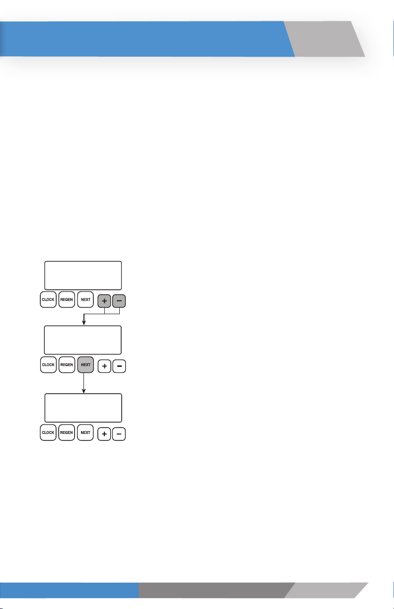
TIME OF DAY MON
GPM
2:408
PM
DAYS SINCE REGEN
5
mA VDC
REGEN 1
OZONE
260 12.0
1. From a general operating screen, press and hold the + and –
buttons simultaneously for three seconds.
2. Once the screen changes, press NEXT until the Ozone
Generator history screen displays.
NOTE: If the Ozone Generator History screen does not
display, ensure that the ozone generator has been turned on
in the programming.
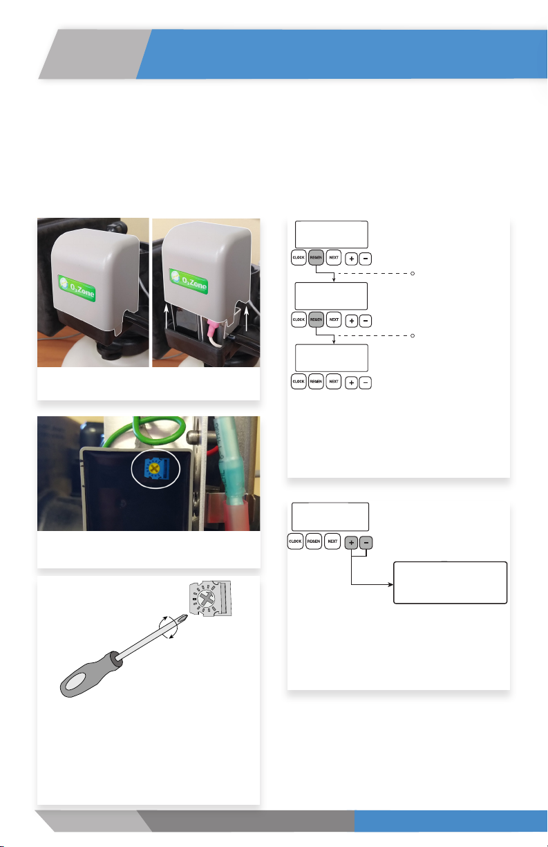
3. Use the + or – buttons to view ozone generator performance
during the last 50 regenerations. A regen sequence indicator (A) will
alternate being viewed with “mA” if the Alternate Regen Feature
was active for this regen. Regens with multiple regenerate draws
will only record the first one in the sequence. Values displayed are
determined immediately after a low output current is detected,
or will be the average values measured during generator period of
operation.
AAA = Generator current draw in mA
VV.V = Generator voltage in VDC
The normal operating amperage should be between 220mA and 260mA. The normal
operating voltage should be between 12.0 and 12.1. When viewing the generator history, be
aware of these values and note any anomalies.

O3zone Generator Kit Instructions
10
Maintenance Instructions
2. Adjust the Potentiometer
If the recorded amperage or voltage is outside of normal levels, the potentiometer may
need to be adjusted. This dial is accessible on the back of the ozone generator unit once
removed from its enclosure and can be adjusted using a screwdriver. To access and adjust,
follow the steps below.
step 1: Remove the cover of the ozone
generator enclosure.
step 2: Locate the Potentiometer on the
back of the generator internals.
step 3: Using a screwdriver, turn the
potentiometer dial fully clockwise. The
potentiometer dial controls the amount of
amperage being supplied from the board
to the generator. Turning it fully clockwise
will supply the lowest amperage to the
generator.
step 4: On the controller, press and
hold the REGEN button until a manual
regeneration is initiated. Press the regen
button to cycle through regeneration
steps until the Regenerant Draw Down
(Air-Draw) step is reached.
TIME OF DAY MON
GPM
2:408
PM
BACKWASH
10:00
REGENERANT DRAW DN
60:00
Press and Hold Until
Regeneration Starts
Press to Move Through
Regeneration Cycles
step 5: Wait on the Regenerant Draw
Down Screen for ten seconds. Press and
hold the Up and Down buttons for three
seconds to reach the ozone generator live-
view screen.
REGENERANT DRAW DN
59:50
mA VDC
GENERATOR
260 12.0

11
Maintenance Instructions
step 6: The live-view screen provides a
live reading of the amperage and voltage
being supplied to the generator. The
ozone generator should read between
220mA-260mA and 12.0VDC-12.1VDC.
Using a screwdriver, gently turn the
potentiometer dial counter-clockwise.
Note the increase in amperage as you
do so. Continue to turn the dial until the
amperage is within the 220mA-260mA
range. Confirm that the voltage reading is
either 12.0 or 12.1.
Turning the dial too far in the counter-
clockwise position can force the generator
to shut down (399mA or over). If this
occurs, the controller screen will appear
“frozen”. Press and hold the NEXT and
REGEN buttons for three seconds to
reboot the board. Once the controller
reboots, return to STEP 3 and continue.
mA VDC
GENERATOR
260 12.0
step 7: Once the amperage and voltage
are within acceptable ranges, press the
NEXT button on the controller to exit the
live-view. Replace the enclosure cover.
If successful, the unit will resume normal
operation and the alarm will cease.
If moisture is suspected to have aected
the cell, such as with a check valve failure
or the result of environmental conditions,
leave the cell to dry by resuming normal
operation. In some cases, the electrical
current running through the cell can dry
it, restoring it to its normal functionality.
If the alarm continues aer three
consecutive regenerations, it is advised to
replace the cell.

O3zone Generator Kit Instructions
12
Maintenance Instructions
3. Replace the Cell
Over time, the ozone generator cell will become clogged with debris, will lose its generating
capabilities, and will require replacement. If adjusting the potentiometer does not solve an
ozone alarm issue, replacing the cell is necessary.
step 1: Disconnect the unit from power
by unplugging the 110V transformer from
its power supply.
step 2: Remove the cover of the ozone
generator enclosure.
step 3: Remove the ozone generator
internal components from the enclosure.
Flip internals over to reveal a screw on the
back. Using a screwdriver, remove and set
aside the screw and the cell clip.
step 4: Detach the current ozone cell
from the generator by pulling connectors
apart and removing it from the cell clip by
pulling away from the generator.
step 5: Attach new cell to the wire
connectors and insert it into the clip.
Re-attach the cell clip and replace the
enclosure cap.
step 6: Reconnect the 110V
transformer to its power supply.

13
Maintenance Instructions
4. Replace the Ozone Check Valve and Injector
Replacement of the check valve and the injector is required yearly for optimal performance
of the ozone generator and filter. This yearly maintenance also prevents check-valve
related failure, which can cause significant water damage to the filtration unit and the area
surrounding it.
step 1: Using a service wrench, loosen
and remove the injector cap.
step 2: Pull out and dispose of the
existing injector. Install the replacement.
step 3: Loosen the nut and remove the
hose connected to the existing air-check
elbow.
step 4: Remove the red clip and
pull upwards on the air-draw elbow to
remove it. Install the new air-draw elbow
by pushing it down into the port and
inserting the red clip until it clicks.

O3zone Generator Kit Instructions
14
Board Replacement Procedure
The Ozone Generator Kit is compatible with XP, WU, and WX style PC Boards. These boards
are characterized by a smaller 4-pin power connector.
WI Series boards are incompatible with the Ozone Generator Kit. For board replacements or
questions regarding compatibility, please contact Water-Right Technical Service at
800-777-1426.
Ozone Generator Compliant Non-Ozone Generator Compliant

15
Maintenance Log
Date Generator Cell Check Valve/Air
Draw Elbow Injector

16
MAN-O3ZONE KIT RevB1119
Table of contents