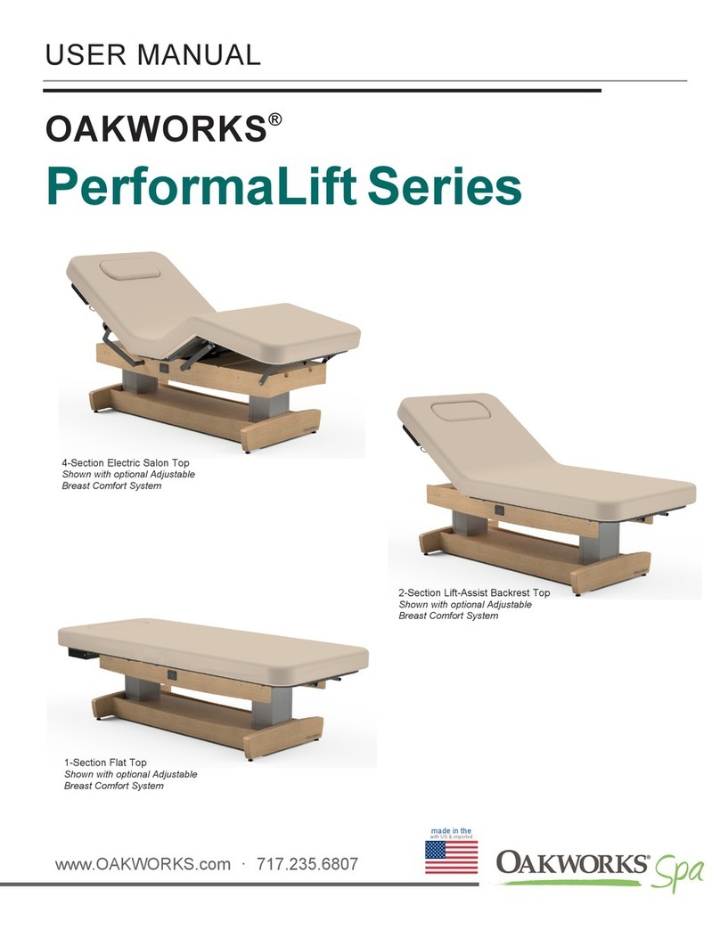
OAKWORKS Spa Clinician Adjustable Lift-Assist Salon Top User manual

OAKWORKS®
Clinician Adjustable
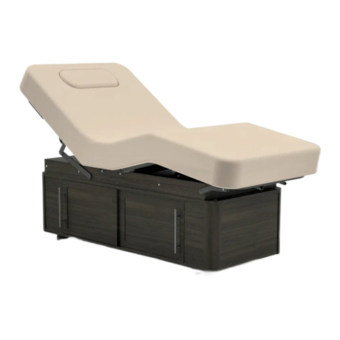
4-Section Lift-Assist Salon Top
Shown with optional Storage
Cabinet
2-Section Lift-Assist
Backrest Top
USER MANUAL
www.OAKWORKS.com · 717.235.6807
made in the
with US & imported
1-Section
Flat Top

© Copyright 2020
OAKWORKS®, Inc.
Printed in U.S.A.
All rights are reserved. No part
of this document may be
photocopied, reproduced or
translated to another language
without prior written consent
of OAKWORKS®, Inc.
OAKWORKS®is a registered
trademark of OAKWORKS®, Inc.
Notice
The information contained within
this document is subject to change
without notice and should not
be construed as a commitment by
OAKWORKS®, Inc.
OAKWORKS®, Inc. encourages
requests for technical
specifications and the like
documentation to ensure accuracy.
The appropriate documentation is
available upon request.
OAKWORKS®, Inc. shall not be
liable for incidental or
consequential damages in
connection with or arising out of
the furnishing, performance, or use
of this document and the program
material which it describes.

TABLE OF CONTENTS
Product Use Description......................................................................................................... 1
Important Safety Instructions
Symbol Identification ..................................................................................................... 1
Safety Instructions ......................................................................................................... 1
Product Description & Photo
4-Section Lift-Assist Salon ............................................................................................ 2
2-Section Lift-Assist Backrest........................................................................................ 3
1-Section Flat Top ......................................................................................................... 4
Installation
Table Assembly ..........................................................................................................5-7
Directions for Use
Lift-Assist Backrest Adjustment..................................................................................... 8
Lift-Assist Leg Rest Adjustment .................................................................................... 8
Moving the Table........................................................................................................... 9
Table Leveling Instructions............................................................................................ 9
Removing Top Pad...................................................................................................... 10
QuickLock Face Rest (Accessory Option) .................................................................. 11
Adjustable Side Arm Rests (Accessory Option - Salon Only)..................................... 12
Boiance Shelf Support (Accessory Option)................................................................. 13
Cleaning & Disinfection
Recommended Cleaners/Disinfectants ....................................................................... 14
Cleaning Process ........................................................................................................ 14
Inspections & Maintenance .................................................................................................. 15
Warranty Information............................................................................................................ 15
Model Number & Serial Number .......................................................................................... 15
Specifications
Environmental Conditions............................................................................................ 16
Dimensions.................................................................................................................. 16
Contact Information .................................................................................................back cover

This symbol, when used in this manual or on product labels, indicates the date of manu-
facture of the device.
This symbol is used to indicate that the operator should consult the user manual.
UL 2601-1
CSA C22.2NO.601.1
IEC 60601-2(2001-09)
CCUSUS
LL
II
SS
TT
EE
DD
R
The Table is designed to be a stand-alone table. This table must not be modified or incorporated into any other
equipment.
As with any moving mechanism there are potential pinch points around and underneath the table It is the
responsibility of the operator of this equipment to insure that bystanders are not in the area below or around this
equipment during operation.
Proper operation of this equipment is very important for the safety of the operator, client, and any other
individuals in the area of this equipment. Directions for use of this equipment are described in this manual.
The operator should read these sections carefully.
Weight Limit: (client and accessories) 500 lbs. (227 kg) Do not exceed.
Be certain that the table is completely lowered without any tilt being present prior to discharging an ambulatory
client. The client may lose balance and fall.
This table is not suitable for use in the presence of flammable anesthetic mixture with air or oxygen or
nitrous oxide.
Do not operate where aerosol (spray) products are being used or where oxygen is being administered.
Do not lift table by the table top. This can damage the table.
When lowering the table, make sure there is nothing underneath the table top that can impede motion (like
stools, cabinets, accessory parts, cleaners, etc)
Use this furnishing only for its intended use as described in these instructions. Do not use attachments not
recommended by the manufacturer.
Close supervision is necessary when this furnishing is used by, or near children, invalids, or disabled persons.
PRODUCT USE DESCRIPTION
The Oakworks Clinician Adjustable offers a variety of positioning capabilities for massage therapists and
spa professionals of all specialties. On these multifunctional professional tables the practitioner can perform
numerous protocols with ease and comfort. The Clinician Adjustable is especially effective when
professional protocols require specific positioning for the client. While the client receives comfortable,
relaxing support, the comfort level of the therapeutic professional is enhanced by superior ergonomics.
It is intended to be operated by Massage Therapists in a professional environment. No special training
is required but a review of the following Safety Instructions is important for the safety of the operator and
client. The massage professional should read and understand this entire manual before use with a client.
There are no known contraindications to the use of this equipment.
The Clinician Adjustable should not be used in any other manner than that described within this manual.
Use of any unnecessary force or unauthorized procedures could result in injury to practitioner, client or
equipment.
SYMBOL IDENTIFICATION
PRODUCT USE DESCRIPTION / IMPORTANT SAFETY
INSTRUCTIONS
IMPORTANT SAFETY INSTRUCTIONS
1

Clinician Adjustable
4-Section Lift-Assist Salon
PRODUCT DESCRIPTION
STANDARD SPECIFICATIONS
Motion 1 Adjustable 26”-37.5” Height Range
Motion 2 Manual 0-80º Backrest
Motion 3 Manual 0-30º Foot Rest
Table Capacity 500 lbs. (227 kg.) (client and accessories)
Widths 29” (74 cm.), 31” (79 cm.), or 33” (84 cm.)
Length 73” (185 cm.)
Padding 4” (10 cm.) or 6” (15 cm.) Aerocel Foam™
Table Weight* 115 lbs. (52 kg)
OPTIONS
Wood Finishes
Sliding Door Storage Cabinet
ACCESSORIES
QuickLock Face Rest
Boiance Shelf Support
Side Arm Rest
2
Shown with optional
Storage Cabinet w/
Sliding Doors

Clinician Adjustable
2-Section Lift-Assist Backrest
PRODUCT DESCRIPTION
STANDARD SPECIFICATIONS
Motion 1 Adjustable 26”-37.5” Height Range
Motion 2 Manual 0-80º Backrest
Table Capacity 500 lbs. (227 kg.) (client and accessories)
Widths 29” (74 cm.), 31” (79 cm.), or 33” (84 cm.)
Length 73” (185 cm.)
Padding 4” (10 cm.) or 6” (15 cm.) Aerocel Foam™
Table Weight* 110 lbs. (50 kg)
OPTIONS
Wood Finishes
Sliding Door Storage Cabinet
ACCESSORIES
QuickLock Face Rest
Boiance Shelf Support
3

Clinician Adjustable
1-Section Flat Top
PRODUCT DESCRIPTION
STANDARD SPECIFICATIONS
Motion 1 Adjustable 26”-37.5” Height Range
Table Capacity 500 lbs. (227 kg.) (client and accessories)
Widths 29” (74 cm.), 31” (79 cm.), or 33” (84 cm.)
Length 73” (185 cm.)
Padding 4” (10 cm.) or 6” (15 cm.) Aerocel Foam™
Table Weight* 105 lbs. (47 kg)
OPTIONS
Wood Finishes
Sliding Door Storage Cabinet
ACCESSORIES
QuickLock Face Rest
Boiance Shelf Support
4

INSTALLATION
TABLE ASSEMBLY
STEP 1
Place the table top upside down on the floor.
STEP 2
Each leg has a number by the top bolt that corresponds with a number on the inside corners of the table top.
(Excluding non-cabinet versions of the Flat top and Back Rest top tables. These legs are universal.) Pick
any leg and match the number. Place the top leg bolt through the metal corner bracket (note – if you have an
adjustable leg section, it may be necessary to raise the leg section to install the leg). Attach washer and nut
and tighten this bolt using the supplied wrench or your own ½” socket wrench. Install one leg only.
STEP 3
Place the shelf upside down on top of the table top. Lift the corner of the shelf and place the bottom leg bolt
through the metal corner bracket of the shelf. Place a flat washer and nut on the bolt and hand tighten only.
5

STEP 5 Cabinet models only
Locate the 3rd leg (match the number), correct end panel (note that there is a large and small end panel)
and one set of doors (note – Top of doors is marked with a “T” on the back side. The front door is marked
with an “F” and the rear door is marked with an “R”.
Insert the 1st set of doors into the tracks and slide towards the center of the table (make sure the “T” is
towards the fabric top). Keep light downward pressure on the shelf to hold the doors and end panel in
place.
STEP 5 Non-Cabinet models only
Repeat Step 4 for each of the remaining legs. Match the number (Excluding non-cabinet versions of the
Flat top and Backrest top tables. These legs are universal). Hand tighten the bolts. After the last leg is
installed tighten all 8 bolts. Table assembly is now complete. Turn table right-side up and proceed to direc-
tions for use.
STEP 4
Find the leg for the opposite corner (match the number). Lift the shelf and insert the 2 leg bolts through the
2 metal corner brackets. Place a flat washer and nut on each bolt and turn the nut into position with the
wrench, but do not completely tighten.
INSTALLATION
6

Tighten the top bolt on all 4 legs (bolt nearest the fabric). Check that doors all slide easily. If they slide easily,
then tighten the 4 leg nuts located on the shelf. If the doors do not slide easily then lift up slightly on the shelf
to produce a small gap between shelf and edge of doors, then tighten the leg shelf bolt. Table assembly is
now complete. Turn table right-side up and proceed to directions for use on next page.
Install end panel - Place correct end panel against previously mounted leg (locate end of panel between pins
and leg flange).
Hold the leg and insert the 2 leg bolts through the 2 metal corner brackets. You may need to wiggle leg and
maybe tap lightly into the final position. Also note that the small angle bracket mounted on the leg fits on the
plastic track. Place a flat washer and nut on each bolt and turn the nut into position with the wrench, but do
not completely tighten. Repeat this procedure for the last leg.
INSTALLATION
7

DIRECTIONS FOR USE
TO RAISE THE BACKREST
Raise the backrest by pressing the lever
under the head section and lifting up to
the desired height. It is recommended that
clients take some of their weight off the
back rest while you lift.
CAUTION
LIFT-ASSIST BACKREST ADJUSTMENT
Do not sit on the backrest section.
TO LOWER THE BACKREST
Press the lever under the head section and
push the backrest down.
LIFT-ASSIST LEG REST ADJUSTMENT
TO RAISE THE LEG REST
Raise the leg rest by pulling the lever on
the side of the leg section and raise to the
desired height. It is recommended that
clients take some of their weight of the leg
rest while you lift.
TO LOWER THE LEG REST
Pull the lever on the side of the leg
section and push the leg section down.
Release the lever once the leg rest is at
its desired location and the leg section will
stay in place.
TO CHANGE POSITION OF THE LEG REST LEVER
The leg rest lever can be moved to the opposite side of the table. First, remove the screws from
the lever and replace the screws. Move the lever to the opposite side of the table. Remove the
screws that are there and mount the lever.
TO CHANGE POSITION OF THE BACKREST LEVER
The back rest lever can be moved to the opposite side of the back rest by removing the
screws and relocating the hand lever to the opposite side of the top into the four pre-drilled
holes.
8

When moving the table, place one person at each end of the table. Have each person firmly grasp the base
at the bottom and lift the table. Be aware and use proper, safe procedures for moving a table of this size to
prevent injury to yourself or the table. We strongly recommend that a flatbed dolly be used that can hold the
entire table when moving the table long distances.
CAUTION
MOVING THE TABLE
The table weighs as much as 115 lbs. (52 kg.) Never lift the table by grasping the table top. You
could damage the table. Two people are required to move the table safely. Do not use the table to
transport a client.
DIRECTIONS FOR USE
at low height range Grasp at base
end rail
TABLE LEVELING INSTRUCTIONS
1. Place the table in the location where you plan to use it.
2. Rock the table to determine if it is level with the floor. If
the table rocks back and forth at all, the foot that clears
the floor when you rock the table will need adjustment.
3. Adjust the Leveler Foot by first loosening the locking
nut found just above the rubber Leveler Foot with the
1/2” open-end wrench.
4. Lower the adjustable rubber Leveler Foot until it meets
the floor snugly. Tighten the locking nut against the leg
of the table with the 1/2” open-end wrench to fix the
Leveler Foot in position.
5. Rock the table again to be sure adjustments have
stabilized the table. If necessary make any additional
adjustments in the same way.
9

DIRECTIONS FOR USE
10
REMOVING TOP PAD
The top pad has been designed to be easily removable and replaceable with no tools needed.
Thumb Screw Locations (4 per side)
1. Unscrew the thumb screw clockwise until the thumb screw is completely
removed. Repeat for all 8 thumb screws. If the thumbs screws are on too
tight, a 5/32” bit can be used.
2. Lift top pad off the platform.
TO REMOVE THE TOP PAD:
The top pad is attached to the platform with 8 thumb screws located below the platform as shown.

DIRECTIONS FOR USE
QuickLockTM FACE REST: (ACCESSORY OPTION)
Double articulating action provides nearly limitless positioning options
with the QuickLock™Face Rest. The adjustable pad takes pressure off
sensitive facial areas while providing superb support. The QuickLock™
Face Rest can be used in both prone and supine positioning and folds out
of the way when not in use. Adjustments are made easily by loosening
the cam locks, adjusting for height and angle and then locking locks into
that position. The table has a bracket at the head of the table for a variety
of uses.
3”
• QuickLock Face Rest Weight Limit - 25 lbs (11.3 kg)
• Do not put excessive weight or pressure on the Face Rest.
• Excessive pressure can cause premature failure of the Face Rest.
CAUTION
ATTACHING QUICKLOCK FACE REST:
When attaching the QuickLock™Face Rest, slide the frame dowels into the bracket until bullet catches
are snapped into place.
To remove the QuickLock™Face Rest, gently pull the headrest by the dowels until it comes free. Set it
safely aside or store it inside the under-table cabinet until needed.
To use the face rest with your clients supine,
rotate the face rest pad so that the thick part of
the pad supports your client’s cervical region.
Adjusting the height and angle of the face rest
gives your clients perfectly comfortable support.
The face pad is flexible so that you can bring
the open ends together or spread them apart to
achieve the most comfortable support for any
size face. To avoid your client’s chin from
hitting the spacebar, make sure the pad is narrow
enough to support their whole face.
For appropriate cervical flexion, use the cam
locks to adjust the downward angle of the face
rest, making sure that the surface of the face rest
pad at the chin is not lower than the surface of
the table.
TIPS FOR GREAT POSITIONING USING THE QUICKLOCK™ FACE REST:
Pull by dowels
Pull by dowels
To remove
11

DIRECTIONS OF USE
ADJUSTABLE SIDE ARM RESTS (ACCESSORY OPTION - SALON ONLY)
CAUTION • Do not use the arm rest for client support during the mounting or dismounting of the chair.
• The arm rest is not designed to support the client’s weight.
TO INSTALL THE ARM RESTS:
The Arm Rests adjust automatically as the back rest moves to remain parallel to the floor.
1. Insert end of arm rest into
backrest hole while holding
the arm rest at a 60° angle
to the backrest.
2. Push end all the way into the hole and drop the arm rest into the
horizontal position. Pull outward to make sure the arm rest is
secure.
TO LEVEL THE ARM RESTS:
The Arm Rest height is adjusted at the factory for each table. If the armrest starts to sag with repeated
use, follow the steps below to readjust.
1. Loosen the bottom 2 set
screws.
2. Turn the side set screw
(clockwise to raise or
counter-clockwise to
lower) while adjusting the
arm rest. Lift the arm rest
slightly when doing this
adjustment to reduce the
weight.
3. Tighten the two bottom set
screws to lock the position.
12

DIRECTIONS OF USE
BOIANCE SHELF SUPPORT: (ACCESSORY OPTION)
• Boiance Shelf Support Weight Limit - 25 lbs (11.3 kg)
• Do not put excessive weight or pressure on the Boiance Shelf Support.
• Excessive pressure can cause premature failure of Boiance Shelf Support.
CAUTION
USING THE BOIANCE SHELF SUPPORT:
The shelf and bracket used together allow you to create the perfect place for clients’ arms. The shelf can
also be used alone as a table extender for additional head support.
Note: The QuickLock Face Rest is required to use the boiance shelf support system.
TO INSTALL THE BOIANCE SHELF SUPPORT:
First install the QuickLock Face Rest at the head end of the table.
1. Position bracket under-
neath QuickLock. 2. Hook bracket onto cen-
ter support beam on
the QuickLock.
3. Lower the bracket down.
Make sure bracket is
engaged with the dowels
on the side of QuickLock.
4. Slide shelf onto bracket.
The top track works best
for this application.
1. Remove face rest from
QuickLock.
2. Slide QuickLock into the
tracks. Top track is best
for 4” foam and bottom
for 6” foam.
For Arm Rest Usage:
For Head Support and
Table Extender Usage:
13

CLEANING & DISINFECTION
RECOMMENDED CLEANERS/DISINFECTANTS
Reference the Recommended Cleaners and Disinfectant list (MMINML0008-EN) that came with the
table. This information can also be found at www.oakworksmed.com under product information.
All cleaners and disinfectants have the ability to degrade the upholstery to some extent. However, fol-
lowing the recommended cleaner and disinfectant list and cleaning process will provided the best care
for your table and support a long product life.
OAKWORKS® recommends a prepackaged wipe for cleaners/disinfectants to ensure best distribution
of disinfectant for the required kill time, without leaving excess residue and/or overexposing compo-
nents therefore minimizing the potential for damage to materials. Please read and follow disinfectants
manufacturers’ directions for cleaning and disinfection.
OAKWORKS® does NOT recommend the use of cleaners/disinfectants containing Hydrogen Peroxide,
Acetic Acid, or Phenolics. These chemicals can cause damage to the appearance and/or material
integrity of various components. Also, while the recommended cleaners/disinfectants list includes
products containing Quaternary Ammonium compounds (“quats”), not all products containing quats
are approved for use. Some contain additional detergents and/or surfactants which can damage some
materials.
A note on Bleach: While a 10% sodium hypochlorite (household bleach) solution (EPA No.: 5813-100
or equivalent) can be an effective disinfectant and is dilute enough to be benign to most materials, it
alone is not an effective cleaner and a separate product must be used for the initial cleaning steps of
the procedure. Because of possible chemical incompatibilities between various cleaning products and
bleach, utmost care must be taken by the user to avoid potential exposure to harmful or toxic by-prod-
ucts of the combination. Also, because bleach leaves a potentially corrosive residue as it evaporates,
it must be rinsed with clean water after disinfection.
Use of non-approved cleaners or disinfectants may lead to damage to upholstery and other
materials found on the table and will void the warranty.
CLEANING PROCESS
Follow the cleaners/disinfectant manufacturers’ directions for use. Please note that cleaning and disin-
fecting an OAKWORKS®table is a two part process. First it must be cleaned of any visible soil, then it
can be disinfected. OAKWORKS® recommends that the table be positioned in the flat position during
the cleaning process. Please follow this procedure for best results:
1. Using an approved cleaner or mild liquid soap and water, clean any visible soil off of the table,
working from the top to the bottom of the table. It is recommended that the upholstery be
cleaned at least once a week to prevent disinfectant build up.
2. Rinse with clean water and dry with a clean cloth or towel.
3. Using an approved disinfectant, thoroughly disinfectant all surfaces of the tabletop and any high-
contact areas such as handles, handsets, etc., making sure they remain wet for the disinfectant
manufacturer’s recommended contact time. Do not allow disinfectant to pool on the upholstery
after the recommended contact time.
4. Wipe off any excess liquid with a cloth or towel and clean water.
5. Dry all surfaces with a clean cloth or towel.
Avoid using writing instruments or other similar instruments around the upholstery as it can cause per-
manent staining. If this does occur, do not wipe with an alcohol based cleaner. Instead, blot the stain
with a clean cloth/ paper towel. Use a 10% bleach dilution to remove the stain. Follow this with a rinse
of clean water.
14

MODEL & SERIAL NUMBERS
The model number and
serial number are located
on the underside of the foot
section of the table top
Model and Serial numbers always start with a letter.
16796025 CLSX4LF1T4XXXXXXXX
Ser#: CLC123456 07/31/2020 Order#:785461
Clinician Adjustable Lift-Assist Salon 1/T/4/XX/XX/XX/XX
TT Stone Notes: XXX
Model Number
Serial Number
INSPECTIONS / WARRANTY / MODEL NUMBER & SERIAL NUMBER
INSPECTIONS
RECOMMENDED REGULAR INSPECTIONS (monthly or local standard)
• Visually inspect components for obvious damage that could cause problems during operation.
RECOMMENDED PERIODIC INSPECTIONS (yearly or local standard)
• Visually inspect components for obvious damage that could cause problems during operation.
• Check that all fasteners are present and fastened securely.
• Clean unusual buildup of dirt on the table and/or parts of the table not normally cleaned on a regular basis.
• Check for tears or cracks in the upholstery.
WARRANTY
View complete warranty details at www.oakworks.com
15

SPECIFICATIONS
16
ENVIRONMENTAL CONDITIONS
Conditions Temperature Humidity Atmospheric Pressure
Normal Use 50° (10°C) to 104° (40°C) 20% to 60% RH 98 to 105 kPa
Storage & Transport -20° (-29°C) to 135° (57°C) 20% to 95% RH 98 to 105 kPa
CABINET DIMENSIONS
Total Inside Dimensions: 53” L x 21” W x 10” H 135cm L x 53cm W x 25cm H
Opening Dimensions:
Head End 26” L x 10” H 65cm L x 25cm H
Opening Dimensions:
Foot End 24” L x 10” H 61cm L x 25cm H

CONTACT INFORMATION:
Oakworks®Inc.
923 East Wellspring Road
New Freedom, PA 17349
Phone: 717.235.6807
FAX: 717.235.6798
www.oakworks.com
USER MANUAL
Original Instructions
Manual Part Number SPA-RA-PM-151
Revision level: 2
Revision Date: 10/12/2020
English, Printed in USA
made in the
with US & imported
OAKWORKS®
Clinician Adjustable
This manual suits for next models
2
Table of contents
Other OAKWORKS Spa Indoor Furnishing manuals