Oase ProfiClear Premium User manual

ProfiClear Premium Trommelfiltermodul
18171/02 H
18171 GA_Trommelfiltermodul_A5_end:. 08.02.12 09:21 Seite 2

2
- -
A
ProfiClear0022
B
ProfiClear0023
C
ProfiClear0024

3
- -
D
ProfiClear0021
E
ProfiClear0020

4
- -
F
ProfiClear0036
G
H
ProfiClear0032 ProfiClear0033
I
ProfiClear0034

5
- -
J
ProfiClear0037
K
L
ProfiClear0060 ProfiClear0061

6
- -
M
ProfiClear0039
N
O
ProfiClear0040 ProfiClear0047

7
- -
P
Q
ProfiClear0044 ProfiClear0043
R
ProfiClear0035
S
ProfiClear0041

8
- -
T
ProfiClear0042
U
ProfiClear0050
V W
ProfiClear0046 ProfiClear0057

39
- GB -
Table of Contents
1Information about these operating instructions.................................................................................41
1.1 Symbols used in these instructions ..........................................................................................41
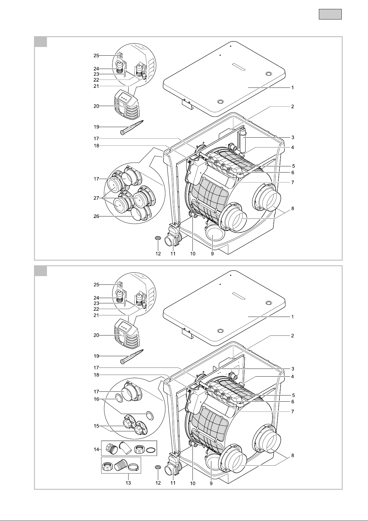
2Scope of delivery...............................................................................................................................41
3Product Description...........................................................................................................................42
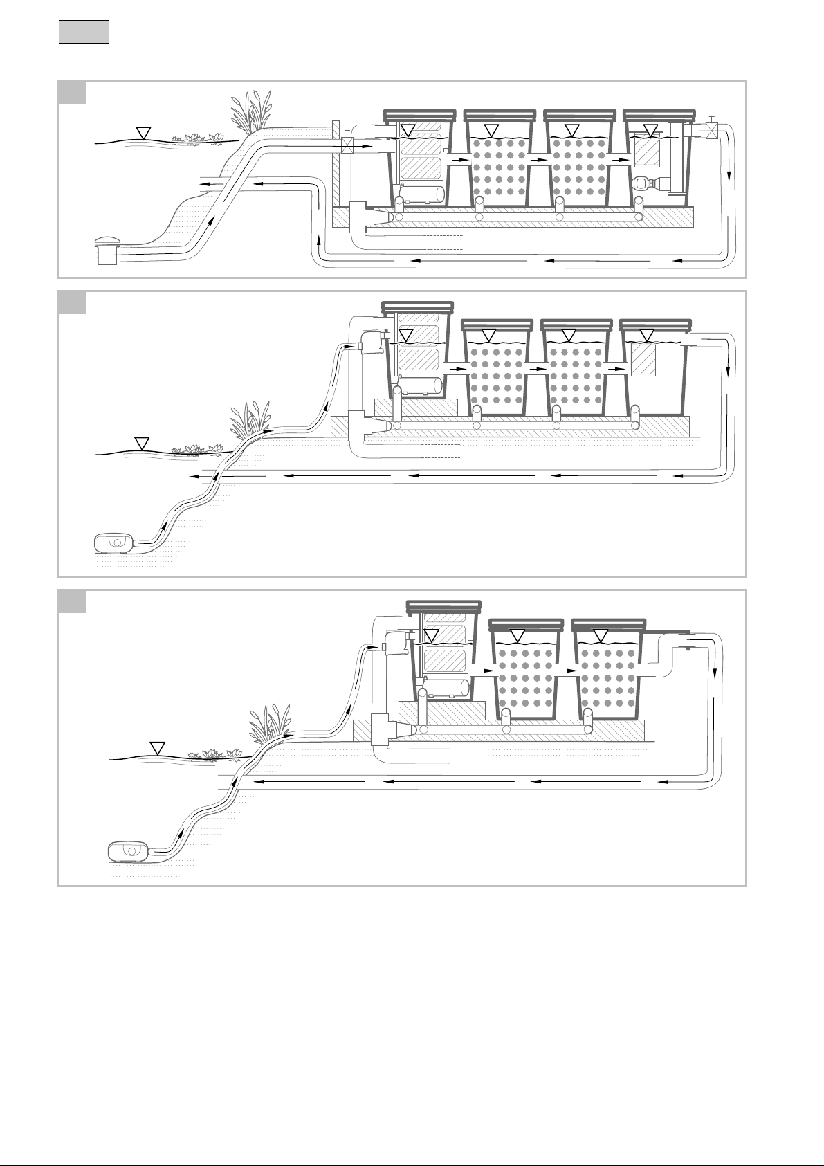
3.1 Gravity fed system....................................................................................................................42
3.2 Pump fed system......................................................................................................................42
3.3 Unit configuration......................................................................................................................43
3.4 Function description..................................................................................................................44
3.5 Intended use.............................................................................................................................44
4Safety information.............................................................................................................................44
4.1 Hazards encountered by the combination of water and electricity...........................................44
4.2 Danger for persons with pacemakers.......................................................................................44
4.3 Correct electrical installation.....................................................................................................45
4.4 Safe operation...........................................................................................................................45
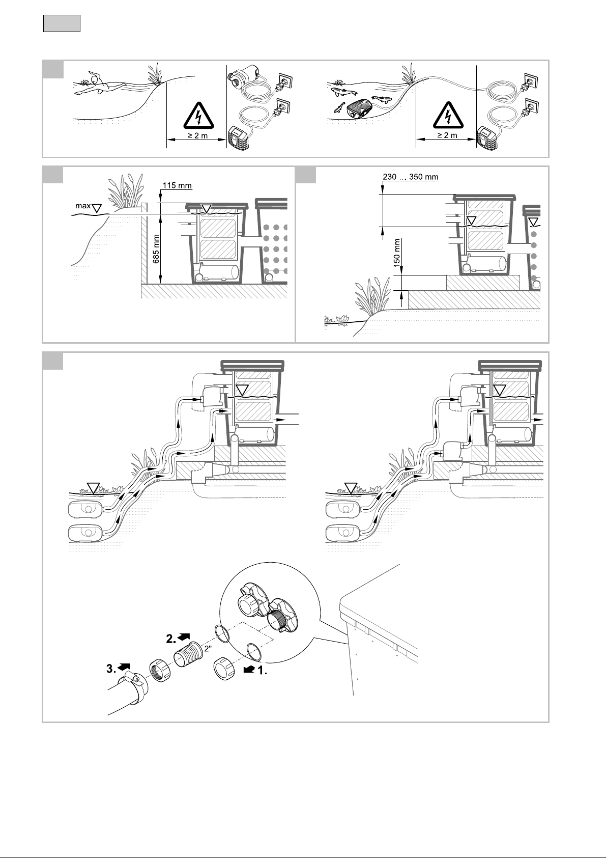
5Installation and connection................................................................................................................46
5.1 Installation planning..................................................................................................................46
5.1.1 Gravity fed system........................................................................................................47
5.1.2 Pump fed system..........................................................................................................47
5.2 Connecting the drum filter.........................................................................................................48
5.2.1 Information regarding pipes..........................................................................................48
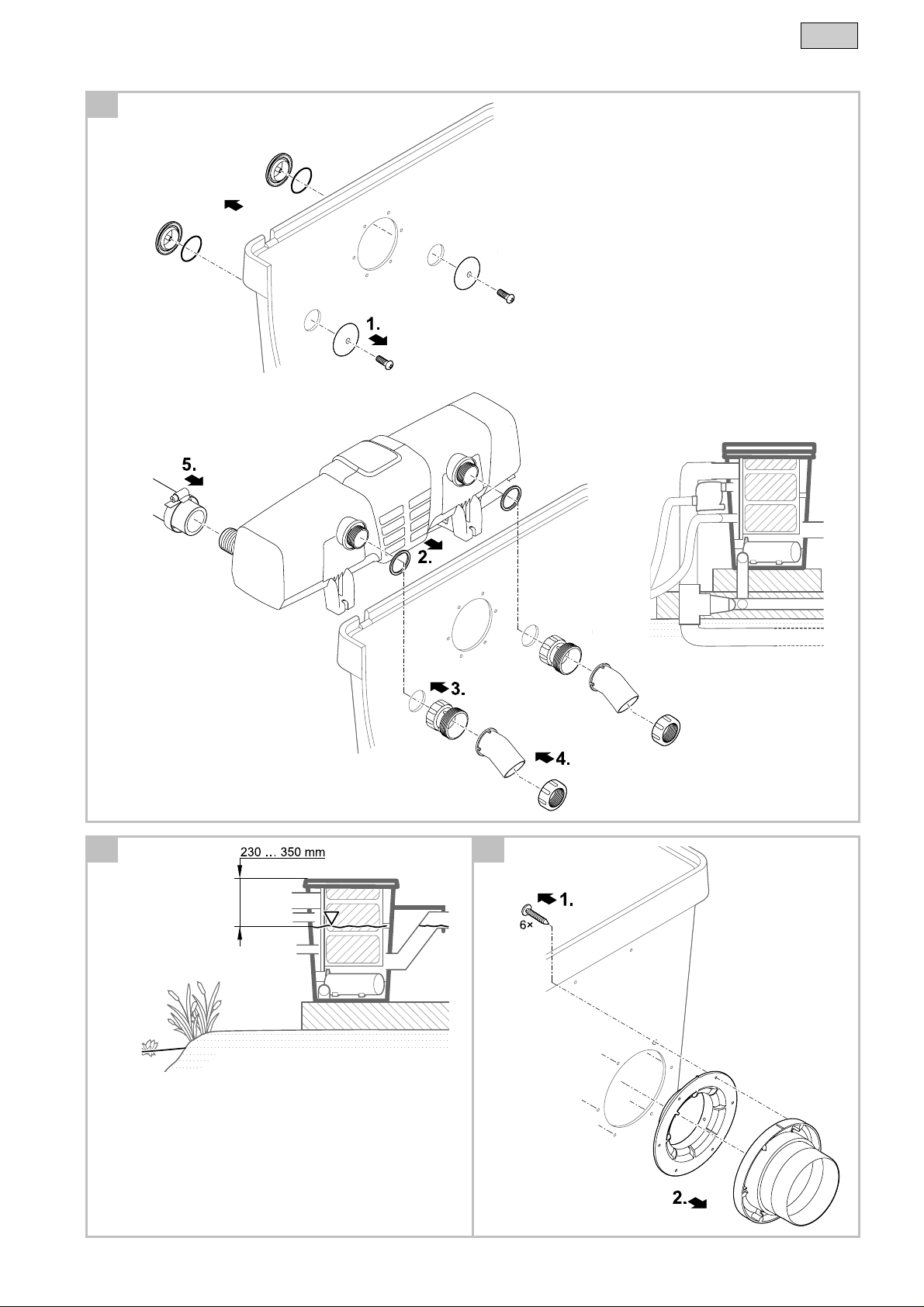
5.2.2 Connecting the inlet......................................................................................................48
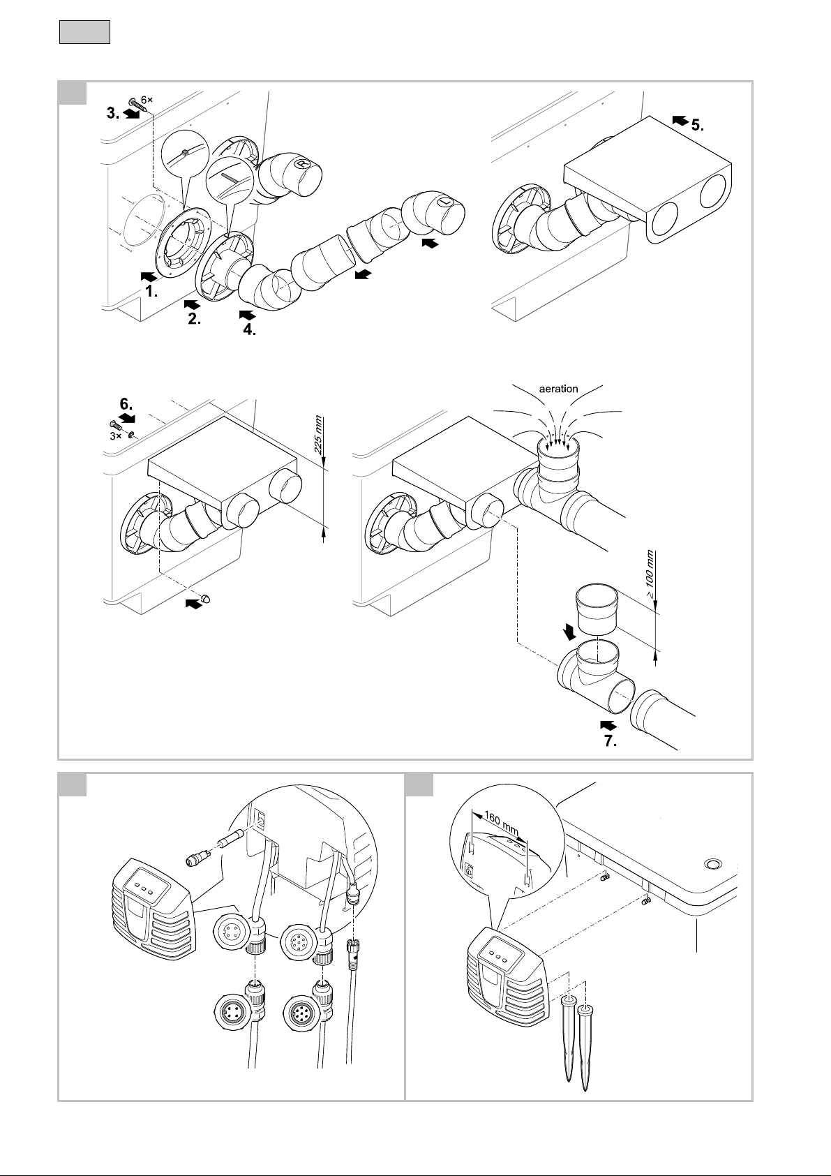
5.2.3 Installation of the UVC clarifying unit............................................................................49
5.2.4 Connecting the dirt outlet..............................................................................................49
5.3 Individual operation of the drum filter module...........................................................................50
5.4 Connecting and installing the control system ...........................................................................51
6Commissioning/start-up ....................................................................................................................52
6.1 Order of starting up steps .........................................................................................................52
6.2 Adjusting the level detection device..........................................................................................54
7Operation...........................................................................................................................................55
7.1 Control system overview...........................................................................................................55
7.2 Switching ON/OFF....................................................................................................................55
7.3 Operating modes ......................................................................................................................56
7.4 Manual cleaning........................................................................................................................56
7.5 Settings in the menus ...............................................................................................................56
7.5.1 C
CL
L: Cleaning time "Cleaning".........................................................................................56
7.5.2 E
EC
C: Extended cleaning time "Extra Cleaning"................................................................57
7.5.3 I
In
n: Time-dependent cleaning "Interval")........................................................................57
7.6 Reading out the number of cleaning cycles..............................................................................58
7.6.1 Cleaning cycles in 24 hours..........................................................................................58
7.6.2 Total cleaning cycles ....................................................................................................58
7.7 Loading default settings............................................................................................................58
7.8 System messages.....................................................................................................................59
8Remedy of faults...............................................................................................................................63
- GB -

40
- GB -
9Maintenance and cleaning............................................................................................................... 64
9.1 Regular tasks........................................................................................................................... 64
9.2 Cleaning the filter system......................................................................................................... 64
9.3 Cleaning the rinsing device...................................................................................................... 64
9.4 Cleaning the screen element................................................................................................... 65
9.4.1 Removing/fitting a screen element.............................................................................. 65
9.4.2 Decalcifying the screen elements................................................................................ 65
9.5 Removing/fitting the filter drum................................................................................................65
14.1 Cleaning the rinsing pump.......................................................................................................66
14.2 Replacing the rinsing pump ..................................................................................................... 66
10 Storage/Over-wintering .................................................................................................................... 67
11 Wear parts........................................................................................................................................ 67
12 Disposal............................................................................................................................................ 67
13 Technical data.................................................................................................................................. 68
Symbols on the unit................................................................................................................................ 339
Spare parts............................................................................................................................................. 340

41
- GB -
Translation of the original Operating Instructions
1 Information about these operating instructions
Welcome to OASE Living Water. You made a good choice with the purchase of this product ProfiClear
Premium Trommelfilter Modul.
Prior to commissioning the unit, please read the instructions of use carefully and fully familiarise yourself
with the unit. Ensure that all work on and with this unit is only carried out in accordance with these
instructions.
Adhere to the safety information for the correct and safe use of the unit.
Keep these instructions in a safe place! Please also hand over the instructions when passing the unit on
to a new owner.
1.1 Symbols used in these instructions
The symbols used in this operating manual have the following meanings:
Risk of injury to persons due to dangerous electrical voltage
This symbol indicates an imminent danger, which can lead to death or severe injuries if the appropriate
measures are not taken.
Risk of personal injury caused by a general source of danger
This symbol indicates an imminent danger, which can lead to death or severe injuries if the appropriate
measures are not taken.
Important information for trouble-free operation.
A Reference to one or more figures. In this example: Reference to Fig. A.
→Reference to another section.
2 Scope of delivery
Gravity fed
system Pump fed
system Description
1 x 1 x Drum Filter Module —
1 x 1 x Control system D, E 19
5 x 5 x 6 × 10 mm fibre disc as a spare D, E 12
2 x 2 x Ground stake for installing the control system D, E 18
— 1 x Connection set, for connecting filter pumps
−2 x 50 mm (2 ") hose connector
−2 x cap nut
−2 x hose clip, 40 ... 60 mm
E 13
— 1 x Connection set, for connecting the Bitron
−2 × 38 / 50 mm (1½ / 2 ") adapter
−2 x 30° infeed curve
−2 x cap nut
−2 flat seal 60 x 47 x 3 mm
E 14
3 x — DN 110 cover cap

42
- GB -
3 Product Description
The OASE filter system ProfiClear Premium includes the filter modules "Drum Filter Module", "Moving
Bed Module" and "Individual Module". The filter system can be operated as a pump fed or gravity fed
system. All filter modules are suitable for both system except for the Drum Filter Module.
3.1 Gravity fed system
A
The filter system is completely buried (filter pit). The inlet opening is located beneath the water level of
the pond. The dirty pond water enters the first filter container via bottom drains or skimmers and then
flows into the following filter modules. According to the principle of communicating pipes (hydrostatic
pressure), the water level balances out in the containers to the level of the pond. A pump in the last filter
module pumps the clean water via a pipe back into the pond.
Advantages of the gravity fed system:
►Excellent transport and thus effective removal of suspended particles using the principle of gravity
►Energy efficient due to negligible height differences and low frictional losses
►Can be unobtrusively integrated in a water garden
►UVC clarifying units can be connected in series behind or, in conjunction with the Bitron Gravity,
before the filter
►Perfectly tailored to the AquaMax Gravity Eco filter pump from OASE
3.2 Pump fed system
B, C
The filter system can be installed above the water level of the pond. A filter pump pumps the dirty pond
water out of the pond into the filter system. The clean water is returned to the pond through a pipe via
gravity.
Advantages of the pump fed system:
►Low installation requirement
►System can be easily extended
►Can be easily connected in front of UVC clarifying units
►Perfectly tailored to the AquaMax Eco Premium filter pumps from OASE

43
- GB -
3.3 Unit configuration
GB Gravity fed
system E Pump fed
system Description
1 1 Container cover
2 2 Signal box with level detection device (3) and temperature probe (4)
−The signal box is connected to the control system (19, 21)
3 3 Level detection device
−Signals the water level in the filter system
4 4 Temperature probe
−monitors the water temperature
5 5 Filter drum with eight screen elements
−screen elements for coarse dirt down to 60 µm in size (also optionally
available with 150 µm)
6 6 Rinsing device
−sprays water at high pressure onto the screen elements (5) to rinse off
the coarse dirt
7 7 Dirt channel
−collects the coarse dirt and rinsing water from the screen elements (5)
8 8 2 x DN 150 outlet
9 9 Rinsing pump for supplying the rinsing device (6)
10 10 Rollers for guiding the filter drum
11 11 DN 75 dirt outlet with slide valve
12 12 5 × spare expansion seals
— 13 50 mm (2 ") connection set
— 14 2 x adapter, 2 x 30° inlet bend with cap nut for connection of the UVC
water pre-treatment device Bitron to 38 mm (1½ ") connections (16)
— 15 2 x 50 mm (2 ") connection for connecting the filter pumps
— 16 2 × 38 mm (1½") connection, closed with sealing plugs
−optional connection for a Bitron UVC water pre-treatment device
17 17 DN 110 dirt outlet for coarse dirt
18 18 Drum motor for filter drum
−the motor is connected to the control system (19, 20)
19 19 2 × ground stakes for installing the control system
20 20 Control system
21 21 Connector for drum motor
22 22 Connector for signal box
23 23 Power cable
24 24 Connector for rinsing pump
25 25 Fuse holder
−Fuse protection of the control system with 5 × 20 mm, T8 A 250 V
safety fuse
26 — −DN 110 inlet
27 — 3 × DN 110 inlets, with cover cap
−For optional use

44
- GB -
3.4 Function description
The main task of the ProfiClear Premium Drum Filter Module is to remove coarse dirt particles.
Screens (60 μm) separate all types of dirt particles before the water reaches the filter biology. By
separating the suspended solids, the filter removes most of the nutrient matter from the water.
In this way, the Drum Filter Module plays an important role in enhancing the filter biology in the Moving
Bed Module and Individual Module. The maximum flow rate in the filter system is 25 m³/h for the pump-
fed system and 33 m³/h for the gravity-fed system.
The control system with integrated microcontroller system automatically controls and monitors the
filtration process. The automatic self-cleaning function can be individually adjusted to meet the user's
requirements.
3.5 Intended use
ProfiClear Premium Trommelfilter Modul, in the following termed "unit", and all other parts from the
delivery scope may be used exclusively as follows:
►For cleaning garden ponds.
►Operation under observance of the technical data.
The following restrictions apply to the unit:
►Only operate with water at a water temperature of min. +4 °C to max. +35 °C.
►Never use the unit to convey fluids other than water.
►Do not use for commercial or industrial purposes.
►Not suitable for salt water.
►Never run the unit without water.
►Do not use in conjunction with chemicals, foodstuff, easily flammable or explosive substances.
4 Safety information
Hazards to persons and assets may emanate from this unit if it is used in an improper manner or not in
accordance with its intended use, or if the safety instructions are ignored.
This unit can be used by children from the age of 8 and by persons with physical,
sensory or mental impairments or lack of experience and knowledge, as long as they
are supervised or instructed on how to use the unit safely and are able to understand
the potential hazards. Do not allow children to play with the unit. Do not allow children
to clean or maintain the unit without close supervision.
4.1 Hazards encountered by the combination of water and electricity
►The combination of water and electricity can lead to death or severe injury from electrocution, if the
unit is incorrectly connected or misused.
►Prior to reaching into the water, always switch off the mains voltage to all units used in the water.
4.2 Danger for persons with pacemakers
►The container cover is equipped with a permanent magnet. The magnetic field may affect the
function of pacemakers.

45
- GB -
4.3 Correct electrical installation
►Electrical installations must meet the national regulations and may only be carried out by a qualified
electrician.
►A person is regarded as a qualified electrician, if, due to his/her vocational education, knowledge
and experience, he or she is capable of and authorised to judge and carry out the work
commissioned to him/her. This also includes the recognition of possible hazards and the adherence
to the pertinent regional and national standards, rules and regulations.
►For your own safety, please consult a qualified electrician.
►The unit may only be connected when the electrical data of the unit and the power supply coincide.
The unit data is to be found on the unit type plate or on the packaging, or in this manual.
►Ensure that the unit is fused for a rated fault current of max. 30 mA by means of a fault current
protection device.
►Extension cables and power distributors (e. g. outlet strips) must be suitable for outdoor use.
►Ensure that the power connection cable cross section is not smaller than that of the rubber hoses
with the identification H07RN-F. Extension cables must meet DIN VDE 0620. requirements
►Protect the plug connections from moisture.
►Only plug the unit into a correctly fitted socket.
4.4 Safe operation
►Never operate the unit if either the electrical cables or the housing are defective!
►Do not carry or pull the unit by its electrical cable.
►Route cords/hoses/lines in a way that they are protected against damage, and ensure that they do
not present a tripping obstacle.
►Only open the unit housing or its attendant components, when this is explicitly required in the
operating instructions.
►Only execute work on the unit that is described in this manual. If problems cannot be overcome,
please contact an authorised customer service point or, when in doubt, the manufacturer.
►Only use original spare parts and accessories for the unit.
►Never carry out technical modifications to the unit.
►The power connection cables cannot be replaced. When the cable is damaged, the unit or the
component needs to be disposed of.
►Keep the socket and power plug dry.
►Overvoltage in the mains could lead to operating malfunctions of the unit. For information, please
refer to chapter "Remedy of faults".
►Do not breath in the spray from the rinsing device. The spray may contain harmful bacteria. When
the container cover is lifted up, the rinsing device continues operating.

46
- GB -
5 Installation and connection
A, B, C
Important: If the planned installation deviates significantly from the recommendations contained in this
manual:
►Have your specialist retailer check whether all technical specifications were adhered to. This is
crucial for a problem-free operation.
5.1 Installation planning
F
Attention! Dangerous electrical voltage.
Possible consequences: Death or serious injuries due to operation of electrical units or installations in
or near swimming ponds.
Protective measures:
►Only use electrical units or installations with a rated voltage of UAC ≤12 V or UDC ≤30 V.
►Observe a distance of 2 m from swimming ponds for operating electrical units or installations with a
rated voltage of UAC > 12 V or UDC >30 V.
►Adhere to national and regional regulations.
Note:
Use suitable transport and lifting aids to transport and install the unit.
The unit weighs more than 25 kg (→Technical Data).
Plan the installation of the filter system. With careful planning, taking the ambient conditions into
account, you will obtain optimum operating results.
The following conditions must be met:
►As the filter modules are very heavy when filled, they must be placed on a suitable base (at least on
slabs, but preferably on a poured concrete base) to prevent them from subsiding.
►Plan sufficient space for carrying out cleaning and maintenance work.
►Drain the dirty water into the drain or far enough away from the pond so that it cannot flow back into
the pond.
−If the coarse soiling and dirty water both run into the same pipe, it is important to use at least DN
110 pipes.
Note:
A water course or waterfall guarantees optimum water return to the pond.
In this way, the filtered pond water is enriched with oxygen before it is returned to the pond.

47
- GB -
5.1.1 Gravity fed system
A, G
System specific requirements
The correct installation and constant water level in the pond are important prerequisites for ensuring
optimum and fault-free operation of the gravity fed system.
Making a filter pit:
►Excavate a pit of sufficient dimensions to accommodate the filter system.
►Horizontally align the base slab.
►Secure the walls of the pit from falling in (with masonry or concrete).
►Ensure that the pit is protected from flooding. Provide a rain water drain.
Installing the filter system:
►Determine the max. water level of the pond.
►The base slab supporting the filter system must be 685 mm below the max. water level (max.
tolerance: -20 mm).
►Keeping the water level constant:
►A constant water level in the pond is necessary for operating the gravity fed system. Tolerances of
up to -20 mm from the max. water level are permitted.
−If the max. water level in the pond is exceeded, water flows out of the Drum Filter Module via the
dirt channel until the max. water level is reached again.
−If the water level goes below the max. water level by more than 20 mm, it is not possible to
achieve optimum or fault-free operation.
►Install the OASE ProfiClear Guard refill system. The ProfiClear Guard refill system automatically
supplies water to the pond if the water level goes below the specified water level.
5.1.2 Pump fed system
B, C, H
System specific requirements
►Horizontally align the base slab.
►Install the Drum Filter Module 150 mm higher than the subsequent Moving Bed Module so that the
connections of the two modules (outlet and inlet) are at the same height.
−Tip: Use three commercially available concrete slabs, each measuring 500 × 500 × 50 mm.
►Position the outlet of the filter system such that the water level in the drum filter module is 230 ... 350
mm below the edge of the container.
−Otherwise, optimum or fault-free operation will not possible.
►Position the inlet in the pond (e.g. via a water course or waterfall) so that it is lower than the outlet of
the filter system.

48
- GB -
5.2 Connecting the drum filter
5.2.1 Information regarding pipes
►Use suitable pipes.
►Do not use any right-angled bends. Bends with a maximum angle of 45° are very efficient.
►Glue plastic pipes to ensure a permanent and reliable joint or use socket joints with clips to stop
them from coming apart.
►Standing water in pipes can freeze when there is a hard frost and cause pipes to burst. For this
reason, lay the pipes and hoses with a gradient (50 mm/m) to ensure that they can run empty.
►For gravity fed systems, it must be possible to shut off the supply from the pond and the return to the
pond for maintenance and repair work. For this reason, install suitable slide valves.
►In the case of the gravity fed system, the sum of the losses in the supply line must not exceed 7
mbar (7 cm).
−Otherwise the water level in the filter system will go below the minimum water level during
operation. Optimum, fault-free operation will no longer be possible.
5.2.2 Connecting the inlet
Gravity fed system
A, D
The drum filter module is equipped with four DN 110 connections.
►Recommendation: Limit the flow rate to 8000 l/h per DN-110 inlet.
►Use suitable DN 110 pipe lines for connecting the bottom outlet and/or skimmer and the inlet.
►Secure the pipes so that fish cannot swim into them.
Pump fed system
The Drum Filter Module has two 50 mm (2 ") connections. Connect one or two filter pumps depending
on the flow rate required.
►You can additionally connect a UVC clarifying unit. (ÆConnecting a UVC clarifying unit)
►The maximum flow rate per connection is limited to 15000 l/h.
5.
How to proceed:
B, I
1. Undo the threaded cap with flat seal from the connection.
2. Screw the union nut with 50 mm (2 ") hose connector and flat seal onto the connection. Hand-tighten
the union nut.
3. Slip the 50 mm (2 ") hose of the filter pump onto the hose connector and secure with a hose clip.

49
- GB -
5.2.3 Installation of the UVC clarifying unit
Gravity fed system
The UVC clarifying unit Bitron Gravity is installed in the Individual Module. (→Please refer to the "Bitron
Gravity" and "ProfiClear Premium Individual Module" operating manuals.)
Pump fed system
The Bitron Eco UVC clarifying unit is fitted to the Drum Filter Module.
►Remove a screen element in order to access the screws of the sealing plugs. (→Replacing a screen
element)
►When two filter pumps are operated, one filter pump is connected to a ∅50 mm (2 ") inlet, the other
to the Bitron Eco. (→Connecting the inlet)
4.
How to proceed:
J
1. Remove both sealing plugs.
2. Guide the outlet sockets of the Bitron with flat seals through the holes in the container wall.
3. Screw the adapters onto the outlet sockets and hand-tighten.
4. Screw the 30° inlet curves with cap nuts onto the adapters and hand-tighten.
−Ensure that the openings point downward.
5. Follow the instructions in the operating manual to connect the Bitron to the filter pump.
5.2.4 Connecting the dirt outlet
D, E
The coarse dirt that collects in the dirt channel drains away via the DN 110 coarse dirt outlet (top outlet
on the container) on the input side.
►Connect a suitable DN 110 pipe and drain the dirty water into the sewer system.
The water in the container can be drained via the DN 75 dirt outlet with slide valve at the bottom of the
container if required (for cleaning, repair, overwintering).
►Connect a suitable DN 75 pipe and drain the dirty water into the sewer system.
Route the two DN 75 and DN 110 pipes together into one pipe and drain the dirty water via a DN 110
pipe into the sewer system. This will ensure that the dirty water pipe will be conveniently flushed out with
sufficient pressure.

50
- GB -
5.3 Individual operation of the drum filter module
K
If no further ProfiClear Premium filter module is connected to the filter module outlets, the height of the
latter needs to be increased. This ensures the required water level in the filter container. The height of
the pipe bend outlet determines the rise level of the water in the filter container. Based on the physical
principle of communicating pipes, the water balances out to the same level in all containers.
OASE provides a suitable discharge set (Order No. 50949). It consists of two pipe bends/DN 110
adapters with holding plate.
To be able to connect the OASE outlet set, both outlets must be changed to DN 110. Remove the filter
drum for this purpose. (→Removing/fitting the filter drum)
Removing the DN 150 outlet
6.
How to proceed:
L
1. Remove the oval-head screw.
2. Remove the outlet and the sealing ring.
Fitting the discharge set
3.
How to proceed:
M
1. If not already done: Fit the sealing ring into the wall of the container from the outside.
−Ensure that the raised marking is at the top and aligned in relation to the hole pattern.
2. Fit the outlet adapter to the sealing ring.
−Ensure that the raised marking is at the top and aligned in relation to the hole pattern.
3. Fasten the sealing ring and outlet adapter from the inside with oval head screws.
−Tighten all screws diagonally using the cordless screwdriver to ensure that the sealing ring is
uniformly applied. Further tighten the screws using a Phillips screwdriver.
4. Fit the pipe bend set together in the specified order and fasten to the outlet adapter.
5. Guide the holding plate over the pipe bend and align the pipe elements if necessary.
6. Insert the screws with expansion seals through the holes from the inside. Screw the holding plate
from the outside to the container wall with cap nuts.
Other manuals for ProfiClear Premium
5
Table of contents
Other Oase Water System manuals

Oase
Oase FiltoClear Series User manual

Oase
Oase Aquamax Expert 20000 User manual

Oase
Oase ProfiClear Guard User manual

Oase
Oase PondJet User manual

Oase
Oase Water Quintet Creative User manual

Oase
Oase SwimSkim 25 User manual

Oase
Oase Aquamax 2000 User manual

Oase
Oase Water Jet Lightning Maintenance and service guide

Oase
Oase ProfiClear Premium TF-XL User manual
Popular Water System manuals by other brands

Grundfos
Grundfos MQ Installation and operating instructions

Armstrong
Armstrong 3760 ProDoseVDG Series Installation and operating instructions

Water
Water HP02 quick start guide

Grundfos
Grundfos UPSe instructions

Kasco
Kasco 1400JF owner's manual

BWT
BWT AQA drink WD CO2 Installation and operating instructions