Oasis NNEBFEZ User manual

NNEBFEZ
Cooler to Bottle Filler Conversion Kit for Single and Split Level
ELKAY EZ8 and LZ8 Water Coolers
INSTALLATION INSTRUCTIONS
1

• Electric drill/driver
• Small tubing cutter for plastic line
• 5/16“ nut driver
• 1/4” nut driver
What’s Included:
Tools & Hardware Required:
Section 1: Getting Started
2
10” of ¼” OD plastic
tubing with 9” of tubing
insulation Installation
instructions
Assembled NNEBFEZ
Cabinet
Side Mounting
Bracket
x2
Drain Elbow
x2
Drainpipe
x2
Center Bracket
¼” Elbow ¼” Union
• Means to cut 1 1/4” drain pipe
•T15 To rx screwdriver or bit
•T20 To rx screwdriver or bit
• 4 appropriate wall anchors (not
supplied)
#8 Torx Screws
x3
#10 Hex Screws
x6
0.25” Terminals
x2
#8 Thread Cutting
Hex Screw
Strain Relief
P-Clip

NNEBFEZ:
Section 2: Rough In Drawing
3

SINGLE LEVEL PREPARATION
4
•Disassembly of ELKAY Cooler
•Wiring
•Water Lines

Section 3: Preparation
5
1. Remove fountain wrapper.
Remove 4x
#10 Hex
Screws
2. Turn OFF water supply to the unit.
Bleed any remaining pressure from the
lines by activating the bubbler valve.
3. Disconnect power by UNPLUGGING
the unit from the wall socket.
4. Loosen or remove the P-trap so that the fountain nose assembly may be freely
removed in the next step.
Loosen or
Remove

Section 3A: Preparation
6
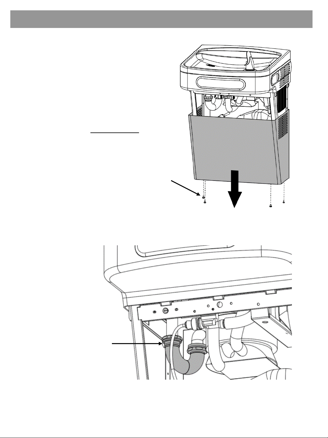
5. Remove fountain nose assembly. Tool Needed: T20 Torx bit
Wires
Water Line
A. Remove 4x #10 Tor x screws from the fountain.
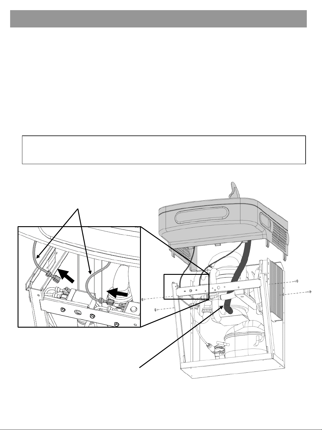
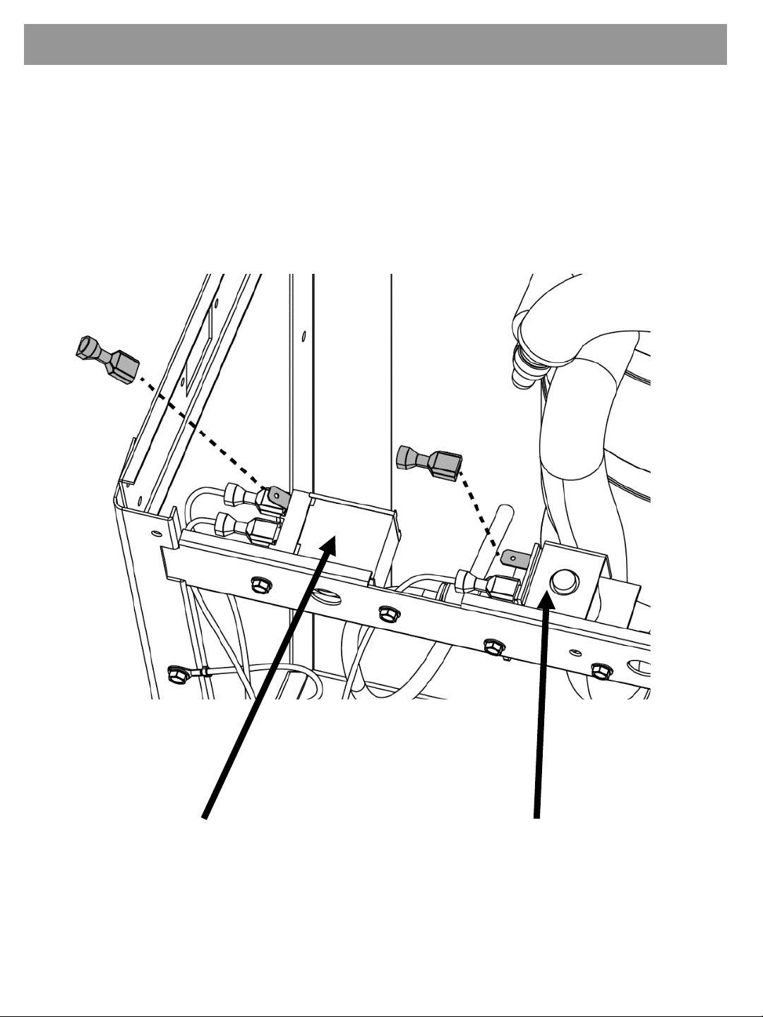
B. Disconnect ONLY the nose assembly wires from the cold control and solenoid valve.
Leave all other wires connected to the cold control and solenoid valve. For non-
refrigerated models, unplug the unit.
C. Disconnect the water line from the bubbler inside the nose. DO NOT disconnect
from the fountain.
DO NOT REMOVE COLD CONTROL OR SOLENOID VALVE
ASSEMBLIES FROM THE FOUNTAIN.
Disconnect only the nose assembly
wires from the cold control and
solenoid valve.

Section 3A: Preparation
7
6. After the nose assembly has been removed, cover the two bare terminals with the
insulated female spade terminals (provided) for safety.
NOTE: The image shown may differ from some models but the instructions will still
apply.
Solenoid ValveCold Control

Section 3A: Preparation
8
7. Locate the solenoid valve on the Elkay unit. Disconnect both water lines from the
solenoid valve. Join the two water lines together using a ¼” elbow fitting (provided) (Fig.
7A).
Allow the cooling tank water outlet line to extend freely upward (Fig. 7B).
Fig. 7B
Cooling Tank Water
Line Out
Fig. 7A
Elbow Fitting
Water Source
Cooling Tank
Water Line In
Shown above is the correct final orientation

9
SINGLE LEVEL INSTALLATION
•Assembly of NNEBFEZ Cabinet
•Wiring
•Plumbing

Section 4: Installation
10
1. The NNEBFEZ comes partially assembled for shipping. Remove the kit from the
packaging and separate it into the assemblies and components shown below. Be sure
not to misplace the provided mounting screws and insulated terminals.
Tool Needed: T15 Torx bit
Drip Tray
Assembly
Filter
Guard
Center
Bracket
Side
Brackets
Frame
Drain
Elbows
Drainpipes
Water
Line
Fittings
Cabinet
Top
Disassemble As Shown
Unpack Parts

Section 4: Installation
11
2. Without taking the cooler off the wall, place the retrofit frame against the wall and set it
onto the top flange of the cooler frame.
Use the two windows at the bottom of
the frame to position it so that the
amount of the cooler frame showing
is equidistant on both sides.
3. Affix the frame to the wall with at least 4 anchors into any appropriate anchor points
through the staggered slotted holes. Be careful to ensure the frame stays centered
on the cooler frame.
Not Provided. Use
appropriate screws/
Anchors for mounting
surface.
x4

Section 4: Installation
12
4. Assemble the center bracket to the holes in each of the cooler struts.
5. Assemble the two side brackets to the cooler frame using the slotted holes on the
bottom with two #10 screws for each bracket. Ensure that the brackets are oriented as
shown below.
Struts
Bracket Orientation
Left Right
#10 Hex Screws
-or -
#10, T20 Torx Screws
(original to fountain unit)
x2
#10 Hex Screws (each bracket)
-or -
#10, T20 Torx Screws (each bracket)
(original to fountain unit)
x2

Section 4: Installation
13
6. Install the drip tray support bracket (keep drip tray pre-assembled) to the center bracket
and frame using 4x, #8 Tor x screws which are provided in the kit.
7. Attach the filter guard bracket with 2x, #8 Tor x screws to the frame and drip tray support
bracket. This bracket helps to prevent the filter cartridge from falling into the cooler unit
below during installation or replacement.
Put BEHIND
center bracket
#8, T15 Torx Screws
x2
#8, T15 Torx Screws
x4

Section 4: Installation
14
8. Attach one of the drain elbows to the drip tray stem. Insert the drainpipe provided into
the elbow and then attach another elbow onto the pipe. Use the remaining drainpipe
and connect the drip tray drainage system to the installed P-trap.
NOTE: Drainpipes will need to be positioned and cut to length as needed.
Drain Elbows
Drainpipes
P Trap

Section 4: Installation
15
9. Assemble NNEBFEZ wrapper to the installed frame. Rest the alcove on the drip tray
and ensure the wrapper walls rest OUTSIDE of the frame and side brackets.
NOTE: The drip tray will hold the weight of the wrapper but it is recommended to
keep a hold on the unit during installation for safety.
#8, T15 Torx Screws
x4

Section 4: Installation
16
10. If the outer edge of the drip tray is not properly aligned, loosen the screws on the back
of the drip tray support bracket and slide the bracket forward or backward as needed.
Then retighten the screws.
11. Once the wrapper has been installed, loosen the side bracket mounting screws until the
bracket can be slid up and down. Adjust the bracket until the mounting hole screws
through the slot and then drive in one of the #8 Torx screws and then tighten the two
#10 mounting screws.
Slotted
Holes
Incorrect alignment
#8, T15 Torx Screws
(1 each side)
x2

Section 4: Installation
17
12. Attach the ¼” union fitting to the Cooling Tank water line out (Fig 12A).
Cooling Tank
Water Outlet
Line Out
Fig. 12A
¼” Union
Fitting
¼” Water Line With
Insulation Tubing
13. Attach one end of the provided ¼” water line with insulation tubing to the solenoid valve
located on the alcove, and the other end to the ¼” union fitting. Cut provided water line
and insulation tubing as needed.

Section 4: Installation
18
14. Guide the power cord down to the lower portion of the cooler. Ensure that the power
cord does not become entangled with other components and ensure that the IEC
connector is firmly installed into the power brick.
Ensure this
connection is
secure

Section 4: Installation
19
15. Install the provided strain relief P-Clip to the power cord roughly 36” from the grounded
plug. Attach it to the back side flange of the fountain frame with a #8 Tor x screw.
(Figure 14a)
16. Attach the ring terminal to the ground screw on the left side of the fountain strut through
the lower flared hole using the provided #8 thread cutting hex Screw. (Fig 15a). Do not
remove/alter the original ground.
17. Finish by plugging in the grounded plug into the duplex socket.
Fig. 14a
Fig. 15a
Second IEC connector
will not be used in a
single level unit.
Grounded Plug
IEC to Power Brick

Section 4: Installation
20
17. Turn on water supply and check for any leaks.
18. Ensure that nothing is obstructing the fan blade.
19. Plug the Elkay power cord into the wall outlet.
20. Test the contactless bottle filler by placing a water bottle into the alcove of the bottle
filler. Check for leaks.
21. Install the cabinet top panel, filter access panel and Elkay cooler wrapper.
22. The NNEBEFEZ comes pre-programmed from the factory. For programming options,
please refer to page 34.
Filter Access
Panel
Top Panel
Elkay
Cooler
Wrapper
#8, T15 Torx Screws
x4
x4 #10 Hex Screws
Table of contents
Other Oasis Accessories manuals