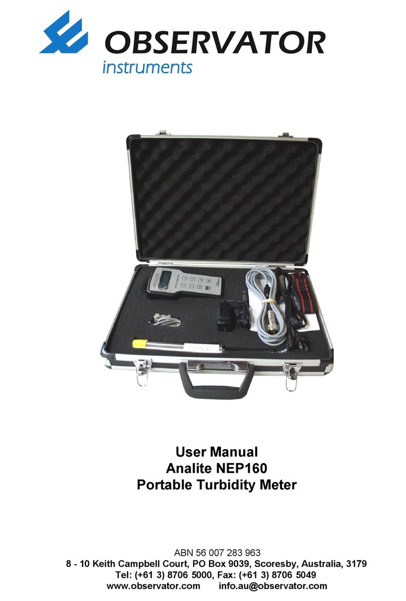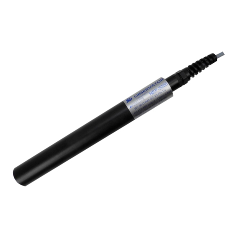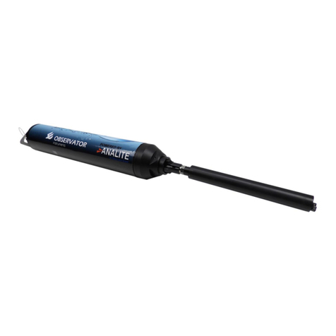
NEP-5000 MANUAL
V2019-08-29
Observator Instruments Copyright 2019 ©
9.2.1. #WD2-A RS232 Glanded .............................................................................................. 45
9.2.2. #WD2-B Analog Glanded ............................................................................................. 47
9.2.3. #WD2-C Voltage Glanded ............................................................................................ 48
9.3. RS485/RS422/Analog Subconn connector option (#WD3) ................................................... 49
9.3.1. #WD3-A RS485 Subconn .............................................................................................. 50
9.3.2. #WD3-B Analog Subconn ............................................................................................. 51
9.3.3. #WD3-C Voltage Subconn ............................................................................................ 52
9.3.4. #WD3-D RS422 Subconn .............................................................................................. 53
9.4. RS485/RS422/Analog Glanded-NEP cable option (#WD4) .................................................... 54
9.4.1. #WD4-A RS485 Glanded .............................................................................................. 55
9.4.2. #WD4-B Analog Glanded ............................................................................................. 56
9.4.3. #WD4-C Voltage Glanded ............................................................................................ 57
9.4.4. #WD4-D RS422 Glanded .............................................................................................. 58
9.5. RS485/Pressure Subconn connector option (#WD5) ............................................................. 59
9.5.1. #WD5-A RS485 Subconn .............................................................................................. 60
9.6. RS485/Pressure Glanded-NEP cable option (#WD6) ............................................................. 61
9.6.1. #WD6-A RS485 Glanded .............................................................................................. 62
9.7. SDI12/Analog Subconn connector option (#WD7) ................................................................ 63
9.7.1. #WD7-A SDI-12 Subconn .............................................................................................. 64
9.7.2. #WD7-B Analog Subconn ............................................................................................. 65
9.7.3. #WD7-C Voltage Subconn ............................................................................................ 66
9.8. SDI12/Analog Glanded-NEP cable option (#WD8) ................................................................ 67
9.8.1. #WD8-A SDI-12 Glanded .............................................................................................. 68
9.8.2. #WD8-B Analog Glanded ............................................................................................. 69
9.8.3. #WD8-C Voltage Glanded ............................................................................................ 70
10. CONNECT TO THE CALIBRATION SOFTWARE ........................................................................ 71
10.1. Install the probe for the first time ........................................................................................ 71
10.1.1. Install Calibration module driver ................................................................................. 71
10.1.2. Run NEP-OEM software ............................................................................................... 73
10.2. Make the calibration connection with the sensor ................................................................ 74
11. TURBIDITY CALIBRATION ..................................................................................................... 77
11.1. When do you need to calibrate? ........................................................................... 78
11.2. Two-point calibration requirements ..................................................................... 78
11.3. Before you begin calibration ................................................................................. 79
11.4. 2-point calibration for 3 Ranges ............................................................................ 81
11.4.1. Clean the sensor .......................................................................................................... 81
