OC3 Solarion M210P User manual

Solarion M210P EN V1.0 2015-10-20 © OC3 AG
Installation and Operation Manual
Solarion M210P
General Information
This document contains important information for the installation of Solarion M210Psolar modules from OC3 AG.
Please read this document before unpacking or installing the solar modules!
Prior to installation, it must be determined that the modules are applicable for the intended use. The interaction with other
system components must be possible without damage to either the modules or said components. All local, national and
international codes, installation and inspection regulations shall apply. Installation and connection of the modules must be performed by a
qualified, authorized expert.
Please be aware that registration of your Solarion modules will increase the product warranty time from 2 to 5
years. By registering your solar modules, OC3 AG will be able to provide better customer support in case you encounter problems with
or have questions about your modules and their installation, operation, use and maintenance. You should also familiarize yourself
with regional, national or international feed-in-tariffs are tax allowances that may be appropriate for your solar system. Solarion
recommends to talk with your installer such that the necessary forms and/or applications that are required by the local electric grid
operator are filled out. Please retain this document for your records.
Liability Exclusion
OC3 AG accepts no responsibility for any losses, damages, injuries or costs that arise when installing, operating, using, maintaining or
otherwise interacting with the module if the cause was due to the non-adherence to the provisions of this installation and
operating manual and the use of the conditions and procedures when installing, operating, using and maintaining the module.
Electrical Danger
OC3 AG recommends that you familiarize yourself with local and national regulations for work safety and accident prevention.
A Solarion solar module generates a direct current (DC) when its front side is exposed to light. Improper handling or placement of the
cables and connectors can lead to dangerous shocks, burns or death, or may lead to fire, particularly when several modules are connected
together in series (higher voltages) or in parallel (higher currents). To prevent accidents, modules should be covered with anon-
transparent, non-abrasive material and under no circumstances connected while under load (i.e. both string poles must be
left unconnected).
Please be aware that arcing may occur when contacts in a live circuit are disconnected! Doing so can lead to fire or cause bodily
injury! Modules under load must never be disconnected from the system! Ensure that no children or unqualified people are
close to the system or the modules during installation.
General Handling and Use
Solarion glass modules are robustly constructed. Nevertheless, please be aware of the following recommendations during handling
and use. Failure to abide by these recommendations will void the warranties of the modules if such actions lead to module damage.
•Do not carry out installation work in rain, snow, ice or strong winds. Always work with solar modules during dry days.
•Ensure that the modules are exposed to ambient temperatures between -40°C and +45°C.
•Wear suitable protective clothing such as safety shoes and protective gloves in order to prevent injuries.
•Impact loads on the front side or edges of the module can lead to irreparable damage and should be avoided.
•The front and back sides of the modules are glass and must not be placed onto hard surfaces.
•Do not step on the module!
•Do not drop or place objects on the modules.
•Always hold the module flat (no bending, torsion, etc. allowed)
•Never carry a solar module by its connector cables or junction box
•Do not stack the modules, either vertically or horizontally, after they have been removed from the package
•Lenses or mirrors must not be used to concentrate light onto the module. The module can be damaged in such cases.
•Always use insulated tools.
•Modules must not be installed in areas where there are risks of explosions.
•Never install damaged modules or modules with damaged cables or junction boxes, as these pose a risk of fire, shock or injury.
•Modifying the module in any way will void the warranty.
•The following applications for Solarion modules are not allowed: indoor use, on moving vehicles, within 500 meter of the coast or
where they are likely to become partially or fully immersed in fresh or salt water.
Mounting Instructions
It is recommended that the customer confirm with the installer that the load of the solar system is compatible with
the statics requirements of the intended area of installation (i.e. roof).
The customer accepts the responsibility to use a safe, load-bearing roof for the Solarion modules. All load-bearing substructures must be
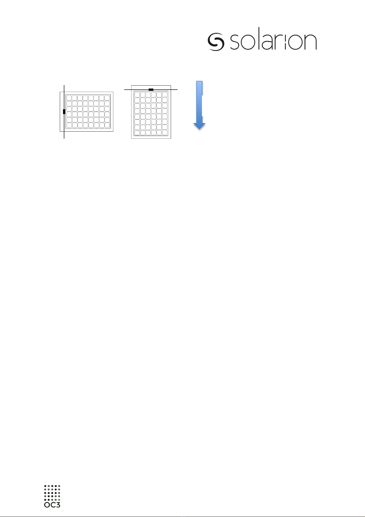
inspected and confirmed for use at appropriate mechanical loads (wind, snow, etc.) by a specialist at the job site.. It is recommended to
mount the module with portrait orientation; landscape orientations should be avoided (see Figure 1).

Solarion M210P EN V1.0 2015-10-20 © OC3 AG
Figure 1: Correct module orientation
A qualified installer should provide to you aplan of your solar system, including module layout, string plan and electrical plan.
Shading of the solar system at times of high irradiation,particularly between the hours of 9:00 and 15:00, should be avoided. It is
recommended that aprofessional installer investigate possible shading instances at all times of the year (e.g. with the aid of aSunEye)
prior to module installation.
The Solarion M210 module is appropriate for flat-roof and low-slope systems with a tilt angle between 3° and 10°.
The likelihood for ponded water is higher on rooftops below 3°, and the possibility for heavy snow loads to place significant stress on the
module junction boxes and cables is high on rooftops above 10°. Where installation sites receive no snowfall or ice build-up, mechanical
fastening of the module must be used on rooftop pitches greater than 40°. Please consult with your roofing specialist or installer.
All mounting components used with the Solarion M210modules must be UL-listed and/or IEC certified and must meet the applicable Code
requirements.
It must be ensured that the intended installation site has adequate drainage and experiences no standing water, even after heavy rainfall.
If the modules are not mounted onto averifiable positive drainage surface according to the presiding roofing codes
at the site of installation, the warranty of the product will be voided. It is also vital to ensure that the upper edges of the
module be suitably protected against snow and ice run-off when installed on pitched rooftops.
Solarion solar modules are guaranteed to support a maximum snow load of 2.4 kPa (2400 N/m2) only when the module is installed on to
roofing membrane or other membrane surface with membrane welding on all 4 edges of solar panel considering backsheet type of solar
module and designated installation surface made from same material. For example if you are going to install this solar panel on to
TPO based membrane, then you should install Solarion M210P PVC modules. If you wish to use a special mounting system that
is not approved for use by Solarion, you must first obtain written permission by OC3 AG, otherwise the guarantee
will be voided.
!
"
Water
Drain

Solarion M210P KEE EN V1.0 2015-10-20 © OC3 AG
Figure 2: Allowable welding areas for mechanical fastening, valid for loads up to 2.4 kPa
The module weldings must be done by hot air welding along the long and short sides of the module. Welding seams should be done
inside of the dotted rectangles.
The edges of the membranes to be welded must be clean and dry. Minimum air temperature at the building site should be 10 °C.
The welding with a 40 mm nozzle has to be done stepwise.
-Step 1. Spot welding: Weld the overlapping seam welding about every 40 cm at a distance of 6 cm from the edge.
-Step 2. Pre-welding: Weld the rear overlap area so that a 4 cm wide area remains for the finishing weld.
-Step 3. Welding: Weld the remaining stripe of 4 cm.
Welding temperature for PVC is 550 °C with a speed of approximately 2 meters per minute. As
accepted good practice, the following installation recommendations should be abided by:
•The bending radius of the cables should be kept to a minimum of 60 mm
•The junction boxes should be positioned on top at all times.
•Bend or twist of the modules (without snow or wind loads) shall be kept < 3 mm/m
•The minimum distance between glass edges of the solar modules should be 150 mm
•Welding seam width between solar module backsheet membrane and membrane surface should be at
least 40 mm
•Welding must be done on all 4 edges of the solar module

Solarion M210P EN V1.0 2015-10-20 © OC3 AG
Figure 3: Welding multiple solar panels on to roofing membrane or other membrane surface
Multiple solar panels can be connected in series and parallel to reach desired power generation.
As accepted good practice, the following installation recommendations should be abided by:
•The solar modules should be welded to each other by their neighbouring edges as shown in Figure 3.
•There must be 150 mm of distance between glass edges of solar panels
•In a group ofsolar modules there space between horizontal groups must be at least 150 mm
•Use Solarion M210P series module for PVC based polymeric installation surface. This is crucial for
proper welding of the solar module on to installation membrane.
Electrical Installation
Modules of the same type (i.e. Solarion M230 KEE) and power class (i.e. 235 Watt) must be used within a serially-
connected module string.A Multicontact junction box is glued to the front side of the module on to membrane backing. Removing
the junction box from the membrane, or opening the junction box will void the module guarantee. The male and
female connectors are labeled with “+” and “-“, respectively. Same-type connectors must be used in the interconnection of Solarion solar
modules. All cables used in the solar system must be appropriate for long-term outdoor use (i.e. UV-resistant) The insulation rating of the
cable must be equal to or greater than the highest expected open circuit voltage (Voc) Please observe all local regulations, such as
building and electrical codes, in your region. In order to avoid damage to the cables, do not lay the cables on sharp edges, and it is
strongly recommended to use cable ties on the cables such that they are not able to sit in standing or run-off water. The cable cross
sections for module interconnections must abide by standard practice with professional standards.
Under certain circumstances, Solarion modules may generate more current or higher voltage as the current and voltage measured at
standard test conditions (STC is defined as an irradiance of 1000 W/m2 at 25°C). It is therefore important to use a minimum safety factor
of 1.25 when specifying string fuses, string diodes, cables and inverters. The maximum system voltage found on the module labels must
not be exceeded.
The use of additional system components such as fault detectors (e.g. RCD, GFDI, etc.), fuses, diodes or circuit breakers may be required
due to local electrical or safety ordnances. Thus safety regulations of these components must likewise be met. Since the glass-membrane
solar panels do not have any accessible conductive parts (i.e. frame), they need not be electrically grounded. Please be aware that
local regulations and codes for functional grounding or substructure bonding of solar systems shall prevail.
Each module string requires the use of serially-connected string diodes in order to avoid the flow of reverse current
from parallel strings or from defective inverters. It is recommended to use rectifier diodes with blocking voltages in accordance
with the appropriate system voltage. The use of string fuses is not mandatory.
For a system voltage of 1000 Volt, a maximum 32 modules are allowed to be serially connected in a single module
string. Based on the aforementioned requirements for the use of string diodes, there is no limit to the number of
strings wired in parallel.
Operation and Maintenance
OC3 AG recommends that a specialist perform any possible required maintenance of your solar system. Routine
maintenance is not necessary; however, it is recommended that the solar system be checked at least once per year for damage, soiling,
etc. Defective modules must be taken out of operation and immediately replaced. Soiling (i.e. pollen, vegetation, bird lime, etc.)
on the front side of the module can be removed with a damp sponge or cotton cloth at ambient temperatures between 10°C and
30°C. De-mineralized water (i.e. soft water) should be used to avoid water stains. Under no circumstances should
abrasive detergents or soaps (i.e. surfactants) be used!
Module Disposal
Module disposal must be done in agreement with local ordinances. The end customer is therefore responsible to correctly dispose of the
modules. If you have any questions on this matter, please contact OC3 AG, and we will consult on proper methods of disposal.

Solarion M210P EN V1.0 2015-10-20 © OC3 AG
www.oc3.ag
www.solarion.de
Table of contents
Popular Solar Panel manuals by other brands

CanadianSolar
CanadianSolar CS3U-350MB-AG installation manual

GOAL ZERO
GOAL ZERO Nomad 7 Plus user manual

Qcells
Qcells Q.PEAK DUO XL-G11S /BFG Series Installation and operation manual

GOAL ZERO
GOAL ZERO BOULER 50 user guide

samlexsolar
samlexsolar SC-05 owner's manual

Jinko Solar
Jinko Solar JKM470N-60HL4 installation manual

Sunsystem
Sunsystem VTC Series Installation and operation manual

evergreensolar
evergreensolar ES-A Series Safety, installation, and operation manual

Ecotech
Ecotech GRID CONNECT SOLAR user manual

CanadianSolar
CanadianSolar CS6A-P installation manual

SILFAB ONTARIO
SILFAB ONTARIO SLAXXXM3A/SLAXXXM Safety and installation manual

Must
Must SM-200W product manual