Oceanled OceanBridge User manual

L I GH T. Y E A R S A H E A D . WWW.OCEANLED.COM
OceanLED MAN-000052 / OceanBridge / Rev1
INSTALLATION & OPERATION MANUAL
OceanBridge

OceanBridge.
INSTALL & OPERATION MANUAL
1
Preface
READ AND FOLLOW ALL INSTRUCTIONS IN THIS MANUAL
IMPORTANT NOTICE
Attention Installer: This manual contains important information about the installation, operation and safe
use of this product. This information should be given to the owner and/ or operator of this equipment.
WARRANTY COVERAGE
Please refer to www.oceanled.com/warranty for full warranty statement.
SAFETY NOTICES
Warning: Product installation and operation
Before installing OceanBridge, read and follow all warning notices and instructions included. Failure to
follow safety warnings and instructions can result in property damage, severe injury, or even death.
Warning: Power supply voltage
Connecting this product to a voltage supply greater than the specified maximum rating may cause
permanent damage to the unit. Refer to the Technical specification section for voltage rating.
Warning: Hazardous or flammable atmospheres
This product is NOT approved for use in hazardous or flammable atmospheres. DO NOT install it in areas
with hazardous or flammable atmospheres, such as engine rooms or near fuel tanks.
Danger: Risk of electric shock or electrocution
This OceanBridge unit must be installed by a licensed or certified electrician in accordance with all
applicable local codes and ordinances. Improper installation will create an electrical hazard which could
result in death or serious injury to swimmers, installers, or others due to electrical shock, and may also
cause damage to property.
Warning: Switch off power supply
Ensure the vessel’s power supply is switched OFF before starting to install this product. Do NOT connect
or disconnect equipment with the power switched on.

OceanBridge.
INSTALL & OPERATION MANUAL
2
IMPORTANT INFORMATION
CAUTION: Power supply protection
When installing this product and using the OceanLED power cable, make sure the power source is
adequately protected by using a suitably-rated fuse or automatic circuit breaker.
Water ingress disclaimer
While the waterproof rating capacity of this product meets IP66 standards, water intrusion and
subsequent equipment failure may occur if the product is subjected to activities such as, but not limited
to, high-pressure washing and/or submersion/flooding. OceanLED will not warranty products if the cause
of failure exceeds the requirements for an IP66 rating.
EMC installation guidelines
OceanLED equipment and accessories conform to the appropriate Electromagnetic Compatibility (EMC)
regulations, to minimize electromagnetic interference between equipment and minimize the effect such
interference could have on the performance of your system.
FCC Compliance
This equipment complies with FCC radiation exposure limits set forth for an uncontrolled environment and
meets the FCC radio frequency (RF) Exposure Guidelines. This equipment should be installed and operated
keeping the radiator at least 20cm or more from the person’s body.
This device complies with part 15 of the FCC Rules. Operation is subject to the following two conditions:
(1) This device may not cause harmful interference, and (2) this device must accept any interference
received, including interference that may cause undesired operation.
FCC Caution
Changes or modifications not expressly approved by the party responsible for compliance could void the
user’s authority to operate the equipment.
This transmitter must not be co-located or operated in conjunction with any other antenna or transmitter.
This device complies with below part 15 of the FCC Rules.
• Part 15 Subpart C
• Part 15 Subpart E
Warning: USB connection
The OceanBridge product is equipped with a USB data connection specifically intended for the connection
of USB memory storage devices. Please DO NOT connect devices with AC power sources, such as PCs or
Laptops, to the OceanBridge product using the USB port. This port is exclusively designed for USB memory
storage devices only to ensure safe and optimal functionality.
Product disposal
Dispose of this product in accordance with the WEEE Directive.

OceanBridge.
INSTALL & OPERATION MANUAL
3
Caution: Service and maintenance
This product does not contain user-serviceable components. Please direct all maintenance and repair
inquiries to authorized OceanLED dealers. Unauthorized repairs could impact your warranty.
Unit cleaning instructions
The unit does not require regular cleaning. However, if you find it necessary to clean the unit, please follow
the steps below:
1. Ensure power is switched off.
2. Wipe unit clean with a damp cloth.
3. If necessary, use a mild detergent solution to remove grease marks.
Changing settings of the device using remote device via Wi-Fi
When changing the Wi-Fi settings, performing a factory reset, or restoring a backup using a remote device
connected via Wi-Fi, be aware that the unit will need to reboot to apply the changes. This reboot will result
in the temporary loss of the Wi-Fi connection with the OceanBridge unit, which will need to be manually
restored based on the applied changes. Additionally the reboot will cause a temporary loss of the DMX
output.
Technical accuracy
To the best of our knowledge, the information in this document was correct at the time it was produced.
However, OceanLED cannot accept liability for any inaccuracies or omissions it may contain. Please check
the OceanLED website (www.oceanled.com) to ensure you have the most up-to-date version(s) of the
documentation for your product. Specifications are subject to change without notice.

OceanBridge.
INSTALL & OPERATION MANUAL
4
Contents
Preface...........................................................................................................................................................................1
1 Introduction................................................................................................................................................................6
1.1 Product Overview .................................................................................................................................................6
1.2 Connections Overview .......................................................................................................................................10
1.3 Diagnostic LEDs and Test/Reset Switch ...........................................................................................................10
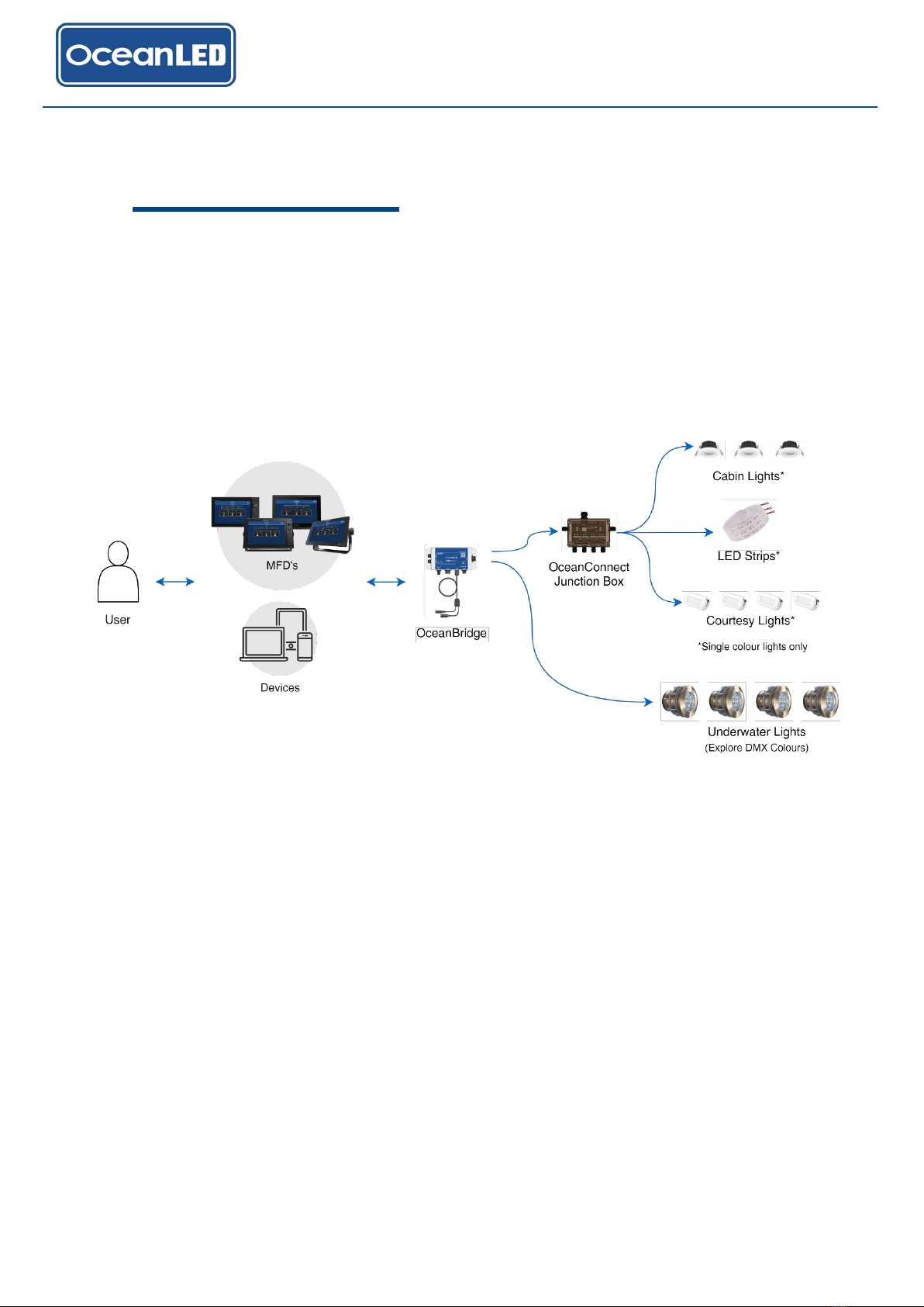
1.4 System Configuration Examples........................................................................................................................11
2 Planning The Installation........................................................................................................................................12
2.1 Parts Supplied ....................................................................................................................................................12
3 Mounting ..................................................................................................................................................................13
3.1 Finding the Mounting Location ...........................................................................................................................13
3.2 Mounting the OceanBridge Unit .........................................................................................................................14
4 Electrical Installation / Wiring ................................................................................................................................15
4.1 Power Connection (without NMEA2000) ...........................................................................................................15
4.2 Connecting via NMEA2000................................................................................................................................16
4.3 MFD Install –Ethernet Connection ....................................................................................................................17
4.4 LAN Ethernet Connection - No MFD..................................................................................................................19
4.5 Audio Connections .............................................................................................................................................19
4.6 DMX Connections...............................................................................................................................................21
4.7 External DMX Controller Connection .................................................................................................................25
4.8 External Switches Connections..........................................................................................................................26
4.9 Final Installation Checks.....................................................................................................................................27
5 System Setup...........................................................................................................................................................28
5.1 First Time Startup ...............................................................................................................................................28
5.2 How to Setup the Equipment .............................................................................................................................33
5.3 Quick Start Launch - Preloaded Simple Setup ..................................................................................................36
5.4 Device Setup ......................................................................................................................................................37
5.5 Zone Setup .........................................................................................................................................................41
5.6 Sweep Setup ......................................................................................................................................................47
5.7 Audio Source Setup............................................................................................................................................48
5.8 Timer Setup ........................................................................................................................................................48
5.9 External Trigger Setup - Switch Functionality....................................................................................................51
6 System options........................................................................................................................................................52
6.1 Network Settings ................................................................................................................................................52
6.1.1. Ethernet .........................................................................................................................................................52
6.1.2. Wi-Fi AP Mode...............................................................................................................................................53
6.1.3. Wi-Fi Client Mode ..........................................................................................................................................54

OceanBridge.
INSTALL & OPERATION MANUAL
5
6.1.4. Bluetooth........................................................................................................................................................57
6.1.5. DMX...............................................................................................................................................................58
6.2 Backup & Restore...............................................................................................................................................58
6.3 How to Perform Factory Reset...........................................................................................................................61
6.4 Background Image .............................................................................................................................................62
6.5 Firmware Update................................................................................................................................................63
6.6 Security...............................................................................................................................................................64
7 General User Guide.................................................................................................................................................66
7.1 Home Page.........................................................................................................................................................66
7.2 Menu Options .....................................................................................................................................................66
7.3 Adjusting Lights Settings and Effect...................................................................................................................67
7.4 How to Activate the Zone, Change Colour, and Apply Effects..........................................................................72
7.5 How to Save / Delete a Scene ...........................................................................................................................74
7.6 Sweep Effects.....................................................................................................................................................75
7.7 How to Activate the Sweep, Change Sweep Effect, and Save as Scene.........................................................76
7.8 NMEA2000 Lighting PGN ..................................................................................................................................78
8 Troubleshooting......................................................................................................................................................80
8.1 Troubleshooting Problems and Solutions ..........................................................................................................80
9 Appendix ..................................................................................................................................................................82
9.1 Technical Specifications.....................................................................................................................................82
9.2 OceanBridge Connectors Pinout........................................................................................................................83
9.3 Dimensions.........................................................................................................................................................84
9.4 RJ45 Waterproof Cover Kit Assembly ...............................................................................................................85
9.5 Optional Accessories..........................................................................................................................................86
9.6 Furuno MFD –Installing the .enc file .................................................................................................................88
9.7 OceanBridge System Installation Diagrams ......................................................................................................90
10 Warranty .................................................................................................................................................................91

OceanBridge.
INSTALL & OPERATION MANUAL
6
1 Introduction
1.1 Product Overview
The OceanBridge is a control unit designed to enable the management of OceanLED lights and third-party lights
through a Multi-Functional Display (MFD) commonly used on marine vessels. Furthermore, it also offers the ability to
manage and control the lighting systems via a Wi-Fi network using various devices such as smartphones, tablets,
laptops, etc.
Compatibility
The OceanLED OceanBridge is compatible with selected MFD units from four main brands: Garmin, Raymarine,
Furuno, and the Navico group (including Simrad, Lowrance, and B&G products). The MFD units must support HTML
app integration and/or NMEA 2000 (N2K) lighting PGNs.
Control Methods
Control of the OceanLED lights can be achieved through multiple methods:
•HTML5 App: Control through an HTML5 app integrated with the MFD unit.
•NMEA 2000 Lighting PGNs: Control via the newly released NMEA 2K lighting PGNs, provided the MFD unit
supports this feature (at the time of writing this document: Simrad, Lowrance, and B&G products only).
•Web Browser Interface: Control through a web-based interface accessible via a Wi-Fi connected device
such as a phone, tablet, or PC.

OceanBridge.
INSTALL & OPERATION MANUAL
7
Supported Lighting Configurations
The OceanLED OceanBridge allows for the configuration of lighting setups, including the setup of zones and
addresses of connected lights via Remote Device Management (RDM). The lighting setup configuration can be
performed through the web-based interface accessible via the Wi-Fi link or the MFD unit.
The OceanBridge supports the following lighting configurations:
•Zone Addressing: Support for up to 10 zones with the following light types:
oFour Channel: RGBW lights
oThree Channel: RGB lights
oTwo Channel: Dual-colour lights
oSingle Channel: Dimmable lights
oSingle Channel: Switchable lights
o2010/3010 Single Colour (legacy OceanLED lights)
oPower Toggle Single (requires OceanConnect JB)
oPower Toggle Dual (requires OceanConnect JB)
DC Switch Lights Support
Basic DC switch lights are supported through an additional DMX-controlled IP66 rated OceanConnect Junction Box.
Please refer to the Appendix for more info.
Audio Support / Integration
The OceanLED MFD Bridge offers support for audio integration. The following audio-related features are included:
•External Audio Input: Support for an external audio (line) input.
•Bluetooth Connectivity: Capability to connect audio devices via Bluetooth.
•Modulation: Ability to modulate the intensity and/or colour of the lights based on an audio source.
•Audio Output: An audio out interface is provided for pass-through of the audio signal or output of the
Bluetooth-connected audio. This interface can be connected to a stereo system or amplifier.
With a zone running in audio mode, the OceanBridge device supports passthrough functionality. This means that
audio signals received through the Audio In connector are passed through to the Audio Out connector. This allows
for seamless audio passthrough without any modifications or processing by the OceanBridge device.
OceanConnect Junction Box

OceanBridge.
INSTALL & OPERATION MANUAL
8
Furthermore, when the OceanBridge device is connected to a Bluetooth audio source, the audio can also be routed
to the Audio Out connector. This means that if the unit is connected to a Bluetooth audio device, users can choose
to listen to the audio output by connecting external audio devices via the Audio Out connector.
Bluetooth Connectivity for Dynamic Audio Mode
The Bluetooth connectivity feature of the OceanBridge device allows for seamless integration with Bluetooth-
enabled audio devices, such as smartphones, tablets, or other compatible devices. This feature enables the
OceanBridge device to synchronize its lighting effects with the audio playing on the connected Bluetooth device,
creating an immersive sound-to-light experience.
Wi-Fi Connection
The OceanBridge Wi-Fi connection supports either of the following modes:
▪Direct Access Point (AP) Mode (default): In this mode, the OceanBridge device acts as an access point itself,
creating its own Wi-Fi network. Users can connect their devices (such as smartphones, tablets, or laptops)
directly to the OceanBridge Wi-Fi network to access its features and functionalities.
▪Client Mode: In this mode, the OceanBridge device functions as a client and can connect to an existing Wi-Fi
network created by a separate router or access point. Users can configure the OceanBridge to connect to their
preferred Wi-Fi network, enabling the device to communicate with other devices on that network.
By supporting both Direct Access Point (AP) mode and Client mode, the OceanBridge device offers flexibility in how
it connects to Wi-Fi networks. Users have the option to either connect directly to the OceanBridge Wi-Fi network or
integrate it into their existing Wi-Fi infrastructure, depending on their specific needs and network setup.
External Switch Control
The OceanBridge device supports up to four external switch inputs, specifically momentary push-to-make type
switches. These switches can be connected to the OceanBridge device to control various functionalities, such as
selecting scenes or controlling the lights.
Key Features:
•External Switch Inputs: The OceanBridge device offers support for up to four external switch inputs,
allowing users to connect momentary push-to-make type switches.
•LED Drive Feedback: The device provides LED drive feedback, enabling compatibility with switches that
have internally illuminated LEDs. This feature ensures that the LEDs on the connected switches function
properly and provide visual feedback.
•Scene Control: The connected external switches can be used to control the lights and select different
scenes. Users can configure the switches to trigger specific lighting configurations or switch between pre-
defined scenes, enhancing the versatility and customization options of the OceanBridge device.

OceanBridge.
INSTALL & OPERATION MANUAL
9
Firmware Upgradability
The OceanBridge device includes USB connectivity, which allows for convenient in-field firmware updates.
•Update from USB Drive: The OceanBridge device supports firmware updates initiated through the
graphical user interface (GUI), such as on your mobile device or MFD. Users can update the device's
firmware by connecting a USB drive containing the updated firmware. Simply insert the USB drive into the
appropriate USB port on the OceanBridge and follow the on-screen instructions to initiate the update
process.
•USB Connection Accessibility: The USB connection is typically accessed through a USB connector with a
removable cap on the device's housing. This design ensures easy access to the USB port when required
for firmware updates. Users can easily remove the cap, connect the USB drive, and proceed with the
firmware update process.
DMX Interfaces
The OceanBridge offers two DMX interfaces which can be configured as:
•Dual Mirror /Output - where both DMX connections are outputs
•DMX Merge (Values takes precedence) –where one DMX connection is used as an input, and the
other as an output. The output DMX values are a ‘merge’ between the incoming DMX from the input
and the OceanBridge generated values. The higher value from either source will be passed to the
output.
•DMX Pass Through –where one DMX connection is used as input and the other as an output. The
DMX signal from the input is passed through the output without modification.
Onboard Test / Reset switch
The OceanBridge device includes on-board Test/Reset switch that provide convenient functionalities for system
testing, resetting, and restoring default settings.
Switch Modes:
•Test Mode: OceanBridge outputs a predefined DMX sequence. This test sequence is specifically designed
to allow users to test the system and observe the behaviour of connected lights or fixtures. By activating the
test mode, users can assess the functioning and connectivity of the system components.
•Reboot: This option enables users to restart the OceanBridge device.
•System/Factory Reset Mode: This option enables users to perform a complete reset, erasing all settings and
configurations stored in the device. By initiating a factory reset, users can start afresh with the device,
eliminating any customized settings or configurations that might have been applied. This action erases all
customized settings and configurations, returning the device to its default state.
Onboard sensors
Gyroscope & Accelerometer Sensor
The OceanBridge device incorporates a gyroscope and accelerometer sensor within its hardware, allowing it to
detect and respond to the vessel's movement. By utilizing the data from these sensors, the device adjusts the
lighting effects to enhance the visual experience. The gyroscope and accelerometer sensor play a crucial role in
creating dynamic lighting effects that synchronize with the vessel's forward/backward movement (pitch) and
left/right movement (roll).

OceanBridge.
INSTALL & OPERATION MANUAL
10
1.2 Connections Overview
1.3 Diagnostic LEDs and Test/Reset Switch
ITEM
FUNCTION
A
DMX Out
B
DMX In/Out
C
NMEA2000 / Power (12/24V)
D
Ethernet
E
Audio In
F
Audio Out
G
Switch Input
H
Diagnostic LEDs
I
Test/Reset Switch
J
USB Port (Memory Stick only)
Diagnostic LEDs (H):
ID
LEDs
STATUS
1
Green - ON
Unit operating properly
2
Amber - ON
Reading Devices (RDM mode)
3
Red - ON
Overheating
4
Amber, Green, Red - ON
Loading System
5
Green, Red - ON
Factory Reset Initialized
Test/Reset Switch (I):
ID
SWITCH
FUNCTION
1
Press once (short press; less than 1s)
Test Mode –The unit will execute power on sequence on all
connected devices
2
Press and hold until Amber LED ON (approx. 5s)
Reboot/Reload the OceanBridge App
3
Press and hold until Red LED ON (approx. 30s)
Factory Reset –All data and settings will be erased

OceanBridge.
INSTALL & OPERATION MANUAL
11
1.4 System Configuration Examples
A schematic diagram showing the locations of all components and cables is an essential aspect of planning any
installation. Furthermore, it proves useful for potential future system additions or maintenance. Below, you can find
examples of basic OceanBridge system installations. See Appendix 9.7 for more examples.

OceanBridge.
INSTALL & OPERATION MANUAL
12
2 Planning The Installation
INSTALLATION CHECKLIST
1. Plan your installation.
2. Obtain all required equipment and tools.
3. Mount the system components.
4. Route all cables.
5. Drill holes for cable routing and mounting as required.
6. Make all the necessary connections to the equipment.
7. Secure all equipment in place.
8. Complete the post-installation check.
2.1 Parts Supplied

OceanBridge.
INSTALL & OPERATION MANUAL
13
3 Mounting
3.1 Finding the Mounting Location
When choosing a mounting location for the OceanBridge the following recommendations need to be followed:
•Consider the wiring routing / connections:
oThe distance to the 12 / 24 V DC power source (or NEMA 2000 connection point/ backbone).
oThe distance to the MFD unit or local LAN network depending on configuration.
oThe distance to the first DMX device/ DMX Junction Box/ OceanConnect JB (i.e. check length of
DMX cable).
•For optimum function of the Wave Motion mode, please consider mounting location and position of the
OceanBridge device, see the illustration below. The unit should be mounted in or as close as possible to
the rotational centre of the vessel –to maximise the accelerations the unit can detect due to wave motion.
Select flat surface in a dry location away from sources of heat.
If planning to use the Wi-Fi / Bluetooth functionality, the unit should be mounted away from metal objects to
ensure good Wi-Fi / Bluetooth coverage. Avoid areas surrounded by metallic insulation or coverings as this
may interfere or restrict the Wi-Fi / Bluetooth signal.
To improve the responsiveness of the movement function the unit should be firmly mounted to a solid
surface directly connected to the vessels structure. (i.e. not mounted to a structure that will move or
vibrate).
For maintenance and checking purposes, leave sufficient space around the unit and some slack in cables.
Minimum recommended space is shown in the outline drawing for the OceanBridge unit –please see
Appendix 9.3 –Dimensions.
OceanBridge Mounting Alignment with Vessel’s Axis

OceanBridge.
INSTALL & OPERATION MANUAL
14
3.2 Mounting the OceanBridge Unit
Once a suitable location has been found, use the following steps to mount the unit:
1. The unit's mounting holes are located at the four corners of the lid.
2. The provided mounting screws are designed to be compatible with various surfaces, such as wood or
fibreglass. Before mounting, mark the desired hole positions and drill pilot holes accordingly. Take caution
to verify the absence of any obstructions, such as cables or pipes, behind the drilling area.
3. Screw the unit to the surface using the screws provided. Never use power tools to mount the unit. Hand
tighten only!

OceanBridge.
INSTALL & OPERATION MANUAL
15
4 Electrical Installation / Wiring
4.1 Power Connection (without NMEA2000)
1. For a straightforward power connection, use the OceanBridge Power Cable (p/n: 013202; not included with
OceanBridge –p/n: 013201). Connect the end with the socket to the OceanBridge NMEA2000/Power port
①and link the other end to the 12/24V DC power source ②typically from the onboard battery. Utilize
waterproof butt splices or IP66 waterproof junction boxes to create watertight connections. This cable must
be protected with a suitable fuse or breaker (1A recommended).
•Connect the +VE Red wire to a +12/24V fused power source.
•Connect the -VE Black wire to the battery - (Ground) supply.
①
OceanBridge Power Connection
②

OceanBridge.
INSTALL & OPERATION MANUAL
16
4.2 Connecting via NMEA2000
To connect to the existing NMEA2000 system, acquire a NMEA2000 drop cable (not provided). If there is no free port
on the backbone, you will need to extend it by adding an additional T-connector (not provided).
Connect the female end of the drop cable to the OceanBridge NMEA2000/Power port ①and the male end to the
NMEA2000 installation backbone ②(T-connector female port). Power for the unit will be supplied through the
NMEA2000 network (Bus Powered).
The maximum drop cable length should not exceed 6 meters. To access the full functionality of
OceanBridge, ensure that the MFD unit is also connected to the OceanBridge unit via an Ethernet cable ③.
For detailed instructions on setting up the MFD Ethernet connection, please consult paragraph 4.3.
②
①
③
OceanBridge NMEA2000 Connection

OceanBridge.
INSTALL & OPERATION MANUAL
17
4.3 MFD Install –Ethernet Connection
Please refer to the Appendix for instructions on assembling the RJ45 waterproof cover kit.
GARMIN
Obtain the Garmin Ethernet cable (not provided). Fit the RJ45 Cover Kit supplied with the OceanBridge over the
RJ45 plug of the Garmin Ethernet cable and connect to OceanBridge Ethernet port. Connect the other end of Garmin
Ethernet cable to the Garmin MFD device (RJ45 socket).
RAYMARINE
Obtain the Raymarine RayNet (F) to RJ45 (M) cable (not provided). Pull back or remove the RJ45 connector boot
from the cable and install the RJ45 Cover Kit supplied with the OceanBridge. Connect the RJ45 plug with the fitted
cover kit to the OceanBridge Ethernet port and connect the other end to the Raymarine MFD device.
Garmin MFD Install - Ethernet Connection
Raymarine MFD Install - Ethernet Connection

OceanBridge.
INSTALL & OPERATION MANUAL
18
FURUNO
Obtain Shielded Ethernet cable (min Cat5e, not provided). Fit the RJ45 Cover Kit supplied with the OceanBridge
over one of the RJ45 plugs and connect to OceanBridge Ethernet port. Connect the other end of the Ethernet cable
to the Furuno MFD fly lead RJ45 socket.
NAVICO GROUP - SIMRAD
Obtain the Navico Ethernet Adapter and Shielded Ethernet cable (min Cat5e, not provided). Fit the RJ45 Cover Kit
supplied with the OceanBridge over one end of the Ethernet cable's RJ45 plug and fit the Navico RJ45 cable boot
over the other end. Connect the RJ45 plug to the OceanBridge Ethernet port and connect the other end to Navico
Ethernet Adapter Cable RJ45 connector. Finally, connect the yellow 5-pin male plug to the SIMRAD Ethernet
yellow 5-pin female socket.
Furuno MFD Install - Ethernet Connection
Simrad (Navico Group) MFD Install - Ethernet Connection

OceanBridge.
INSTALL & OPERATION MANUAL
19
4.4 LAN Ethernet Connection - No MFD
The OceanBridge unit can connect directly to the local vessel's LAN network (switch/router) without the need for the
MFD unit. All functionalities can be accessed using devices such as a laptop/PC, smartphone, or tablet, as long as
they are connected to the same network via an Ethernet cable (for PCs) or Wi-Fi. Please obtain a Shielded Ethernet
cable (min Cat5e, not provided). Use the RJ45 Cover Kit supplied with the OceanBridge to cover one end of the
Ethernet cable's RJ45 plug. Connect the covered end to the OceanBridge Ethernet port and the other end to the
Router/Switch.
OceanBridge Ethernet Connection with Router/ Switch
4.5 Audio Connections
The OceanBridge device includes the following audio connectors:
•1 x Audio In 3.5mm stereo connector : This connector allows for the input of audio line-in signals from
external sources. Users can connect devices such as smartphones, MP3 players, or other audio devices to
play audio through the OceanBridge.
•1 x Audio Out 3.5mm stereo connector : This connector serves as an output for audio line-out signals. It
enables users to connect external audio systems to enjoy the audio output from the OceanBridge device.
Use the 'Audio In' input when connecting an external device as the source of the audio signal. Depending on your
audio device, you will need the appropriate extension cable (not provided). Connect the 3.5mm stereo input jack to
the OceanBridge 'Audio In' fly lead input jack socket and connect the other end to the external audio source. Ensure
to waterproof the audio connection. Damage to the OceanBridge unit through poor installation of third party cables
will void your warranty.
For best results use the ‘line-out’ connection from an audio source, rather than a headphone outlet, as
levels should not change with volume.
Other manuals for OceanBridge
1
Table of contents
Popular Gateway manuals by other brands

ProSoft Technology
ProSoft Technology PLX3 Series user manual

Chesterton
Chesterton 415198 user manual

ZyXEL Communications
ZyXEL Communications ZyWALL USG Series Application note

ZyXEL Communications
ZyXEL Communications 3415 installation instructions

NETGEAR
NETGEAR CGD24Nv2 user manual

OpenVox
OpenVox DGW-100XR user manual