oConnor 1030D Manual

1030D/Ds Ultimate HeadFluid
C1237-0001
C1239-0001
Operators Guide
C1239-4980/1
ONLINE REGISTRATION:
HTTP://REGISTRATION.OCON.COM


OConnor
1030D/1030Ds
Fluid Head
Operators Guide
Publication Part No. C1239-4980 Issue 1

Copyright © 2011 The Vitec Group plc
All rights reserved throughout the world. No part of
this document may be stored in a retrieval system,
transmitted, copied or reproduced in any way,
including, but not limited to photocopy, photograph,
magnetic or other record without the prior agreement
and permission in writing of the Vitec Group plc.
Trademarks
OConnor™ is a registered trademark of
the Vitec Group plc.
Important information about this document
Information contained within this document is subject
to change. Camera Dynamics Limited reserves the
right, without notice, to make changes in equipment
design or performance as progress in engineering,
manufacturing or technology may warrant.
Published by
Vitec Group Videocom Division
Technical Publications Department
William Vinten Building, Western Way
Bury St Edmunds, Suffolk IP33 3TB
United Kingdom
E-mail: [email protected]

1030D/1030Ds Fluid Head
3
Preface
Congratulations on the purchase of your new 1030D/1030Ds fluid head from OConnor!
We want you to get the most from your new 1030, and therefore encourage you to read this
operator’s guide to familiarize yourself with its many features, some of which may be new to you.
It also covers essential health and safety information and a section on maintenance that will
ensure your new product is kept in perfect condition.
Please register your purchase online at www.ocon.com.
Features and benefits of your new 1030
• The 1030D/Ds is the smallest in OConnor’s Ultimate range of fluid heads and
features OConnor’s stepless counterbalance system as well as ultra-smooth
pan and tilt fluid drag designed for cine-style shooting.
• A new collapsible counterbalance crank handle makes balancing the payload
easier. The new 1030 has all controls on the camera operator’s side of the
head (on the left or ‘smart’ side) and features platform scales and two rosette
handle mountings on either side of the head.
• OConnor’spatentedfluiddragsystem allowsextremelyquickpanmovements
from one position to another, recovering instantly without any springback.
• You can set up easily in low light conditions using the illuminated bubble level.

Operators Guide
4
Safety – read this first
Warning symbols in this Operators Guide
Where there is a risk of personal injury or injury to others, comments appear
highlighted by the word ‘WARNING!’—supported by the warning triangle symbol.
Where there is a risk of damage to the product, associated equipment, process or
surroundings, comments appear highlighted by the word ‘CAUTION’.
Disposal of waste batteries
Batteries included with this product must not be treated as household waste. By ensuring these
batteries are disposed of correctly, you will help prevent potentially negative consequences for
the environment and human health, and help conserve natural resources.
Refer to the section ‘Replacing the battery’ (page 17) in this manual for instructions on how to
remove the battery from the product safely. Hand the battery over to the applicable collection
point for recycling waste batteries.
Contact information
For further information or advice about the Ultimate range of fluid heads, please contact
OConnor at:
OConnor
2701 N. Ontario St.
Burbank, CA 91504
USA
Tel.: +1 818 847 8666
Fax: +1 818 847 1205
E-mail: [email protected]
Or visit our website www.ocon.com and use the contact form.

1030D/1030Ds Fluid Head
5
Technical specification
Dimensions
Height (incl. camera platform) . . . . . . . . . . . . . . . . . . . . . . . . . . . . . . . . . . . . . .6.6 in. (16.8 cm)
Width . . . . . . . . . . . . . . . . . . . . . . . . . . . . . . . . . . . . . . . . . . . . . . . . . . . . . . . . .7.6 in. (19.3 cm)
Depth . . . . . . . . . . . . . . . . . . . . . . . . . . . . . . . . . . . . . . . . . . . . . . . . . . . . . . . . . 4.6 in. (11.7 cm)
Weight . . . . . . . . . . . . . . . . . . . . . . . . . . . . . . . . . . . . . . . . . . . . . . . . . . . . . . . . . 8.7 lbs (3.9 kg)
Payloads and ranges
Note: Payload capacity and tilt ranges are based on a C of G height of 6" (15 cm).
1030D
Capacity (see counterbalance graph, Figure 3)
Minimum payload. . . . . . . . . . . . . . . . . . . . . . . . . . . . . . . . . . . . . . . . . . . . 0 lbs (no load)
Maximum payload . . . . . . . . . . . . . . . . . . . . . . . . . . . . . . . . . . . . . . . . . . 30 lbs (13.9 kg)
Tilt range. . . . . . . . . . . . . . . . . . . . . . . . . . . . . . . . . . . . . . . . . . . . . . . . . . . . . . . . . . . . . . . . ±90°
Pan range. . . . . . . . . . . . . . . . . . . . . . . . . . . . . . . . . . . . . . . . . . . . . . . . . . . . . . . . . . . . . . . 360°
Counterbalance . . . . . . . . . . . . . . . . . . . . . . . . . . . . . . . . . . . . . . . . . . . . . . . . . . . . . continuous
1030Ds
Capacity (see counterbalance graph, Figure 4)
Minimum payload. . . . . . . . . . . . . . . . . . . . . . . . . . . . . . . . . . . . . . . . . . . . 0 lbs (no load)
Maximum payload . . . . . . . . . . . . . . . . . . . . . . . . . . . . . . . . . . . . . . . . . . 41 lbs (18.6 kg)
Tilt range. . . . . . . . . . . . . . . . . . . . . . . . . . . . . . . . . . . . . . . . . . . . . . . . . . . . . . . . . . . . . . . . ±60°
Pan range. . . . . . . . . . . . . . . . . . . . . . . . . . . . . . . . . . . . . . . . . . . . . . . . . . . . . . . . . . . . . . . 360°
Counterbalance . . . . . . . . . . . . . . . . . . . . . . . . . . . . . . . . . . . . . . . . . . . . . . . . . . . . . continuous
Mounting
Base. . . . . . . . . . . . . . . . . . . . . . . . . . . . . . . . . . . . . . . . . . . . . . . . 100 mm ball base (standard)
150 mm ball base, Mitchell base (optional)
Camera mounting platform. . . . . . . . . . . . . . . . . . . . . . . . . . . mini Euro or large Euro (optional)

Operators Guide
6
Contents
Page
Preface . . . . . . . . . . . . . . . . . . . . . . . . . . . . . . . . . . . . . . . . . . . . . . . . . . . . . . . . . . 3
Features and benefits of your new 1030 . . . . . . . . . . . . . . . . . . . . . . . . . . . . . . . . . . . . . . 3
Safety – read this first . . . . . . . . . . . . . . . . . . . . . . . . . . . . . . . . . . . . . . . . . . . . . . 4
Warning symbols in this Operators Guide . . . . . . . . . . . . . . . . . . . . . . . . . . . . . . . . . . . . . 4
Contact information . . . . . . . . . . . . . . . . . . . . . . . . . . . . . . . . . . . . . . . . . . . . . . . . 4
Technical specification . . . . . . . . . . . . . . . . . . . . . . . . . . . . . . . . . . . . . . . . . . . . . 5
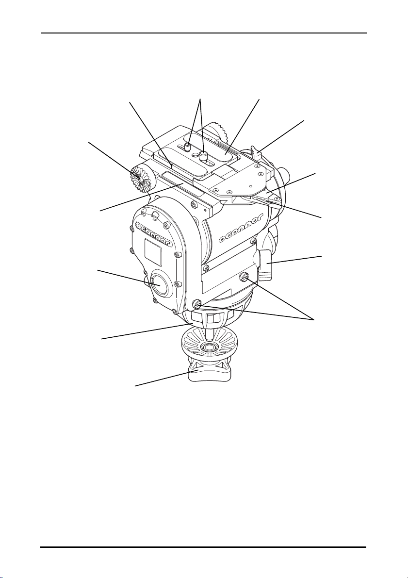
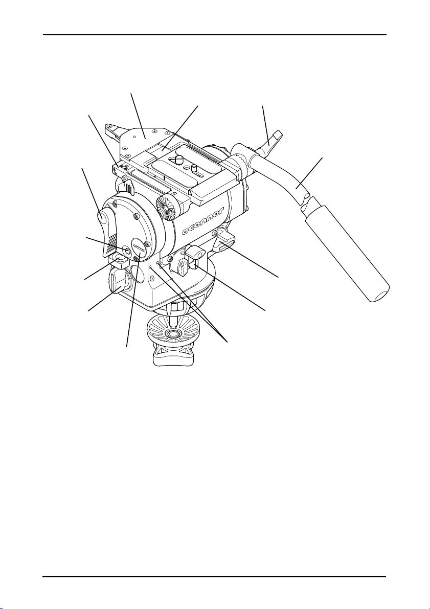
Components . . . . . . . . . . . . . . . . . . . . . . . . . . . . . . . . . . . . . . . . . . . . . . . . . . . . . .7
Introduction . . . . . . . . . . . . . . . . . . . . . . . . . . . . . . . . . . . . . . . . . . . . . . . . . . . . . .9
Counterbalance . . . . . . . . . . . . . . . . . . . . . . . . . . . . . . . . . . . . . . . . . . . . . . . . . . . . . . . . . 9
Ultra-smooth fluid drag. . . . . . . . . . . . . . . . . . . . . . . . . . . . . . . . . . . . . . . . . . . . . . . . . . . . 9
Pan and tilt locks . . . . . . . . . . . . . . . . . . . . . . . . . . . . . . . . . . . . . . . . . . . . . . . . . . . . . . . . 9
Illuminated bubble level . . . . . . . . . . . . . . . . . . . . . . . . . . . . . . . . . . . . . . . . . . . . . . . . . . 10
Handle mounting . . . . . . . . . . . . . . . . . . . . . . . . . . . . . . . . . . . . . . . . . . . . . . . . . . . . . . . 10
Camera mounting platform . . . . . . . . . . . . . . . . . . . . . . . . . . . . . . . . . . . . . . . . . . . . . . . 10
Bases. . . . . . . . . . . . . . . . . . . . . . . . . . . . . . . . . . . . . . . . . . . . . . . . . . . . . . . . . . . . . . . . 10
Operation . . . . . . . . . . . . . . . . . . . . . . . . . . . . . . . . . . . . . . . . . . . . . . . . . . . . . . . 11
Installing the head . . . . . . . . . . . . . . . . . . . . . . . . . . . . . . . . . . . . . . . . . . . . . . . . . . . . . . 11
Handles . . . . . . . . . . . . . . . . . . . . . . . . . . . . . . . . . . . . . . . . . . . . . . . . . . . . . . . . . . . . . . 11
Mounting the camera. . . . . . . . . . . . . . . . . . . . . . . . . . . . . . . . . . . . . . . . . . . . . . . . . . . . 11
Stability. . . . . . . . . . . . . . . . . . . . . . . . . . . . . . . . . . . . . . . . . . . . . . . . . . . . . . . . . . . . . . . 12
Balancing the head . . . . . . . . . . . . . . . . . . . . . . . . . . . . . . . . . . . . . . . . . . . . . . . . . . . . . 12
Fore and aft balance . . . . . . . . . . . . . . . . . . . . . . . . . . . . . . . . . . . . . . . . . . . . . . . . . 13
Payload weight and counterbalance . . . . . . . . . . . . . . . . . . . . . . . . . . . . . . . . . . . . . 14
Pan and tilt locks . . . . . . . . . . . . . . . . . . . . . . . . . . . . . . . . . . . . . . . . . . . . . . . . . . . . . . . 14
Pan and tilt fluid drag. . . . . . . . . . . . . . . . . . . . . . . . . . . . . . . . . . . . . . . . . . . . . . . . . . . . 15
Storing the head. . . . . . . . . . . . . . . . . . . . . . . . . . . . . . . . . . . . . . . . . . . . . . . . . . . . . . . . 15
Servicing . . . . . . . . . . . . . . . . . . . . . . . . . . . . . . . . . . . . . . . . . . . . . . . . . . . . . . . . 16
General . . . . . . . . . . . . . . . . . . . . . . . . . . . . . . . . . . . . . . . . . . . . . . . . . . . . . . . . . . . . . . 16
Routine maintenance. . . . . . . . . . . . . . . . . . . . . . . . . . . . . . . . . . . . . . . . . . . . . . . . . . . . 16
Cleaning. . . . . . . . . . . . . . . . . . . . . . . . . . . . . . . . . . . . . . . . . . . . . . . . . . . . . . . . . . . . . . 16
Adjusting the lock levers . . . . . . . . . . . . . . . . . . . . . . . . . . . . . . . . . . . . . . . . . . . . . . . . . 16
Replacing the battery. . . . . . . . . . . . . . . . . . . . . . . . . . . . . . . . . . . . . . . . . . . . . . . . . . . . 17

1030D/1030Ds Fluid Head
7
Components
Figure 1 1030D/Ds Fluid Head, right-hand side (front)
handle/accessory
mounting rosette
front box
mounts
camera
mounting plate
platform scales
camera plate
release lever
tilt drag indicator
wheel
pan lock
lever
platform release
lever
ball base
(100 mm)
camera plate
marker camera screws
red safety
catch
tie down
(100 mm)

Operators Guide
8
Figure 2 1030D/Ds Fluid Head, left-hand side (rear)
counterbalance
crank handle
(fold-out)
tilt drag
adjustment knob
handle clamp
handle
pan drag
adjustment knob
battery
compartment
tilt lock lever
level bubble
level bubble
button
provision for
attachments
platform hook
platform sub-base
platform

1030D/1030Ds Fluid Head
9
Introduction
The 1030D/Ds fluid head comprises a patented sinusoidal counterbalance mechanism for true
and accurate balance, stepless drag assemblies for ultra-smooth pan and tilt motions. It comes
complete with an adjustable top platform with detachable camera mounting plate, a telescoping
handle, and a 100 mm ball base.
The 1030 head features provisions for mounting a front box and for attaching an eye-piece
leveler or other accessories at the rear.
Counterbalance
The balance mechanism is adjusted by the counterbalance crank on the rear of the head. The
crankhasa magnetic foldinghandle. Maximum andminimum payloads that can bebalanced are
dependent on the weight of the camera and accessories, and on the Center of Gravity (C of G)
height. The counterbalance graphs for the 1030 heads show the range of loads and C of G
heights that can be maintained in balance (see pages 12 and 13).
The counterbalance is continuous and can be adjusted all the way to zero (no counterbalance),
andthe head canstill be tiltedwithin itsspecified tilt range(see‘Technicalspecification’,page 5).
Ultra-smooth fluid drag
Both the pan and tilt mechanisms incorporate OConnor’s patented ultra-smooth fluid drag to
ensure smooth movement. The pan drag adjustment knob and indicator wheel are located on
the left side of the head, below the level bubble, and the tilt drag adjustment knob is located on
the lower right rear of the head with the indicator wheel on the right side end cover.
Both controls are continuously adjustable from 1 through 5.
Pan and tilt locks
Friction locks on each axis allow the head to be locked at any desired position. The pan lock
lever is on the lower left front of the head, at a convenient angle for manual operation, and the
large tilt lock lever sits just above the level bubble on the left side of the head, for easy operation.
The 1030D/Ds has a reversed pan break in comparison to previous versions of the 1030. This
has been done to match the break arrangement of the larger OConnor heads (see ‘Pan and tilt
locks’ on page 14), to further ease the transition from larger payload camera setups to smaller
payload camera setups for the operator.
CAUTION!
1. Do NOT overcrank or undercrank the crank handle (i.e. wind the crank handle
above or below the end stops). Adjusting the counterbalance crank by force
can seriously damage the head.
2. Before operating the head, ensure that the crank handle is returned to its
folded position.

Operators Guide
10
Illuminated bubble level
The bubble level on the left side of the head can be illuminated by pressing the bubble level
illumination button. The light will extinguish after approximately 25 seconds. When the head
leaves the factory a battery is installed and tested.
Handle mounting
Two handle mounting rosettes are located at the rear of the head, on the left and right side. A
telescoping extension handle is supplied and is attached using the handle clamp, with angular
adjustment available on the rosette serrations. An additional handle or other accessories can
also be installed.
Camera mounting platform
The camera is attached to the head by means of a top platform mechanism. Two quick-release
top platforms using different mechanisms are available. They are secured by means of a
platform stop—a 6/32 x ¼ in. socket head cap screw that requires a 7/64 in. hex drive wrench.
The head comes standard with an adjustable camera mounting platform. The camera can be
released quickly by pressing the red safety catch and rotating the camera plate release lever
approximately 180° in a clockwise direction. At the end of lever travel the platform hook retracts
and the spring mechanism ejects the camera mounting plate allowing easy removal of the
camera/payload from the head.
Bases
The 1030 head is supplied with a 100 mm ball base as standard. However, like all other Ultimate
range fluid heads from OConnor, the base can be exchanged either for a Mitchell base and tie
down, or a 150 mm ball base and tie down. All bases are secured by eight small fasteners—the
4-40 x .375 in. socket head cap screws require a 3/32 in. hex drive wrench.
WARNING!
Ensure the camera platform is attached securely. The platform stop must be
fixed before mounting the camera/payload.

1030D/1030Ds Fluid Head
11
Operation
Installing the head
The 1030D/Ds fluid head can be installed onto standard tripods using the 100 mm ball base or,
alternatively, a 150 mm ball base or Mitchell base, and tie downs as required.
Aftersecurelymounting the head onto the tripod, usethebubble level to set it level.If necessary,
press the bubble level illumination button to view the bubble level in poor light conditions. The
bubble will be lit for approximately 25 seconds.
Handles
Install the handle(s) on the rosette handle mount(s) and adjust the position before tightening the
handle clamp(s). Adjust the length of the telescoping handle as desired.
Mounting the camera
To mount the camera:
1. Level the head and engage the tilt lock.
1. Remove the camera mounting plate. Press the red safety catch to unlock the camera
plate release lever and rotate the lever approx. 180° in a clockwise direction to eject the
mounting plate.
2. Attach the mounting plate to the bottom of the camera.
3. Insert the mounting plate into the platform. Push it into the groove towards the front of
the head, then down until the platform hook engages with an audible ‘click’ (the plate
release lever will have jumped back approx. 90° upon the ‘click’). The camera is now
captive, but not locked.
4. To lock the camera mounting plate, push in the red safety catch and rotate the camera
plate release lever counterclockwise, approx. 90° to the left. The red safety catch will
engage locking the lever, and thus securing the camera and payload.
5. Install the remainder of the payload (lens, zoom and focus controls, viewfinder, etc.)
before unlocking the tilt lock.
WARNING!
Do NOT fit the head to a tripod that cannot support the combined mass of
the head and payload (refer to ‘Technical specification’ on page 5 for the
maximum payload capacity of the relevant head).
WARNING!
1. Ensure that the weight and C of G height of the total payload is within
the range for which the head is designed.
2. If you are installing the head on a crane, pedestal, or dolly, you must
lock these before installing the camera.

Operators Guide
12
Stability
Use the mid-level or floor spreader to ensure that the tripod legs are spread sufficiently, so that
the C of G of the tilted payload remains within the footprint of the tripod.
Balancing the head
Make sure that the head is level before balancing. Check the bubble level to verify that the head
itself is level and make sure that the platform is also level.
Balancing the 1030 head achieves two objectives: First, when a head is correctly balanced, the
operatorwill onlyneed a minimumamount of effortto movethe camera.Second, oncebalanced,
the head and its payload can be set to any tilt position and the head will maintain this position
with ‘hands off’.
The chart below shows the range of load and C of G heights that can be maintained in balance.
The area below the balance curve (to the left) corresponds to load/C of G combinations that can
bebalancedover the fulltilt range of±90° for the 1030D(Figure 3)and ±60° for the1030Ds head
(Figure 4), respectively. The area above the balance curve (to the right) corresponds to load/
C of G combinations that exceed the capacity of the head.
WARNING!
When mounting the head on a tripod, it is possible to set the tripod legs so
that the C of G of the tilted payload falls outside the footprint of the tripod,
leading to instability.
NOTE: It is important that the handle(s) and all camera accessories (lens, zoom and
focus controls, viewfinder, etc.) are fitted in their operational position before
balancing the head. Any equipment fitted or adjusted later can unbalance the
head requiring the camera setup to be rebalanced.
Figure 3 Counterbalance chart – 1030D
1030D COUNTERBALANCE CHART
10 20 30 40 50 60 70 80 90 100110120130140150
4.5 9 1418 232732 364145 505460 6468
12
10
8
6
4
251
102
152
203
254
305
0
CAMERA CENTER OF GRAVITY
ABOVE PLATFORM
CAMERA WEIGHT
in mm
lbs
kg
14
16
18
356
406
457

1030D/1030Ds Fluid Head
13
Fore and aft balance
1. Make sure the tilt lock is engaged and that the camera and all accessories are installed
in their operating positions.
2. Set the tilt drag adjustment knob to ‘1’ (lowest setting).
3. Initially, set the counterbalance quite low.
4. Holding the handle to steady the platform, disengage the tilt lock.
5. Tilt the platform forwards and backwards and determine whether the camera payload is
front or back heavy. Depending on the payloadweight, it may be necessary toadjust the
counterbalance to enable the payload to be correctly balanced fore and aft.
6. If it is not in balance, re-engage the tilt lock.
7. Disengage the platform release lever by pulling it away from the platform.
Figure 4 Counterbalance chart – 1030Ds
WARNING!
When positioning the payload, it is important to be aware of the potential
danger that an unbalanced payload will fall away suddenly.
Always be prepared for this by maintaining a firm hold of the handle, until
the balance is set correctly.
WARNING!
In the event of the head falling away violently, increase the counterbalance
setting.
1030DS COUNTERBALANCE CHART
10 20 30 40 50 60 70 80 90 100110120 130140 150
4.5 9 14 182327 3236 41455054 606468
12
10
8
6
4
251
102
152
203
254
305
0
CAMERA CENTER OF GRAVITY
ABOVE PLATFORM
CAMERA WEIGHT
in mm
lbs
kg
14
16
18
356
406
457

Operators Guide
14
8. Carefully slide the camera payload and platform forwards or backwards, until the
payload is balanced fore and aft. The horizontal balance is correct when no perceptible
tilting force can be felt on the handle with the platform level and the tilt lock disengaged.
9. Lock the platform to secure the balanced camera payload in position. Engage the
platform release lever by pushing it firmly towards the platform.
10. If there is insufficient movement in the platform to achieve balance:
Determine in which direction the mounting plate needs to be moved to achieve correct
balance. Remove the payload from the head, reattach the mounting plate to the camera
in the required position, remount the load and repeat the horizontal balancing procedure.
11. The camera mounting plate is marked and the head has scales on both sides; make a
note of the “balanced” position to simplify rebalancing this particular payload.
Payload weight and counterbalance
The fore and aft balance must be set before adjusting the payload weight and counterbalance.
1. Using the handle tilt the platform downwards and upwards. When correctly balanced,
there should be no perceptible tilting force on the handle at any angle of tilt and the head
should remain in any tilt position to which it is set.
2. If necessary, adjust the counterbalance as follows:
• If the head tends to fall away when the platform is tilted, set the platform level and
turn the crank handle clockwise to increase the counterbalance.
• If the head tends to spring back when the platform is tilted, set the platform level and
turn the crank handle counterclockwise to decrease the counterbalance.
3. Using the handle tilt the platform upwards and downwards to recheck the balance.
Adjust the counterbalance, until balance is achieved.
4. When balancing is complete, check that the fore and aft balance is still correct. Readjust
the position of the platform, if necessary.
5. Exercise the head through the full range of pan and tilt to confirm that it operates
smoothly.
Pan and tilt locks
The pan and tilt friction locks are operated by levers on the left side of the head.
Rotate the pan lock lever clockwise to engage the pan lock.
Rotate the tilt lock lever counterclockwise to engage the tilt lock.
Ifa lock doesnot fully engageat the endofthe locklever travel, referto ‘Adjusting the locklevers’
on page 16 in the Servicing section.
CAUTION! The locks should be applied whenever the camera/head is left unattended.

1030D/1030Ds Fluid Head
15
Pan and tilt fluid drag
Both the pan and tilt mechanisms incorporate the OConnor ultra-smooth fluid drag system to
ensure smooth movement. The pan drag adjustment knob is located below the level bubble on
the left side of the head and the tilt drag adjustment knob on the lower right rear of the head.
Both controls are continuously adjustable from 1 through 5.
To increase drag, turn the knob clockwise, towards a higher setting.
To decrease drag, turn the knob counterclockwise, towards a lower setting.
Storing the head
When shooting is finished and the head is to be stored, head settings (i.e. counterbalance and
fluid drag) should be left unchanged. This will reduce wear on the head’s mechanisms and save
time on the next shoot. The head should be covered or stored in a bag/case when not in use.

Operators Guide
16
Servicing
General
The 1030D/Ds Ultimate fluid head is robustly made to high engineering standards and little
attention is required to maintain serviceability except for regular cleaning. Repairs and any
adjustments beyond those described in this manual should be carried out by qualified persons
only. Contact OConnor headquarters (see page 4), your local OConnor office or representative.
Routine maintenance
Replace the battery whenever the bubble level illumination is inadequate.
During normal use, check the following:
• Check the effectiveness of the pan and tilt locks. Reset as necessary (refer to
‘Adjusting the lock levers’ on page 16 for instructions).
• Check the operation of the illumination of the bubble level. Replace the battery as
necessary (refer to ‘Replacing the battery’ on page 17).
No further routine maintenance is required.
Cleaning
During normal operation the only cleaning required is a periodic wipe-down with a lint-free cloth.
The head should be covered or stored in a bag/case when not in use. Any dirt that accumulates
during storage or periods of non-use may be removed with a vacuum cleaner. Particular
attention should be paid to the camera mounting area.
Use out-of-doors under adverse conditions may require special attention. Salt spray should be
washed off immediately using fresh water. Sand and dirt act as an abrasive and should be
removed using a vacuum cleaner.
Adjusting the lock levers
If the pan and/or tilt friction locks do not fully engage at the end of the lock lever travel, adjust
the lever position as follows:
1. Rotate the lock lever to the “locked” position (see Figure 5).
2. The lock lever is attached by means of an M4 x 8 mm screw. Carefully peel off the lock
label to expose the screw. Using a 2.5 mm Allen or hex key remove the screw.
3. Pull the lock lever off the hexagonal shaft, rotate it approx. 30° away from the “locked”
end of travel, and reinstall it.
4. Tighten the screw. Reapply the lock label.
NOTE: Do NOT use solvent-based or oil-based cleaners, abrasives or wire brushes to
remove accumulations of dirt as these will damage the protective surfaces.
Use mild, detergent-based cleaners only.

1030D/1030Ds Fluid Head
17
Replacing the battery
The battery illuminates the bubble level. It should be replaced whenever the illumination
becomes inadequate.
1. If required, rotate the tilt lock lever to access the battery cover (Figure 6).
2. Use a coin or flat-blade screwdriver to unscrew the battery cover.
3. Carefully pull the battery out of its compartment using the ribbon.
Figure 5 Adjusting the pan and tilt lock levers
Figure 6 Replacing the battery
lock label
tilt lock lever
shaft
screw
battery cover
button battery
tilt lock lever

Operators Guide
18
4. Fit a replacement CR 2032 3V battery in the compartment, ensuring that the positive
side (+) of the battery faces outermost and that the ribbon is correctly positioned.
5. Replace the battery cover and tighten using a coin or flat-blade screwdriver.
6. Press the bubble level illumination button and verify that the bubble level lights up. It
should be lit for approximately 25 seconds.
This manual suits for next models
3
Table of contents
Other oConnor Camera Accessories manuals