OCULUS SDI 4 User manual

OCULUS SDI®4
INSTRUCTION MANUAL
Stereoscopic Diagonal Inverter

i / iii Instruction Manual SDI® 4 (G/54320/EN 0220 Rev01)
Notes on this instruction manual
The SDI® 4 has been manufactured and tested according to strict quality criteria.
To ensure safe operation, it is essential that you use the device correctly. For this
reason, you should thoroughly familiarize yourself with the contents of this instruction
manual before operating the device. In particular, pay attention to the safety
instructions.
This operating manual describes the following SDI® 4 models:
SDI® 4c
SDI® 4e
SDI® 4m
Due to ongoing development, the diagrams shown in the instruction manual may
depict minor changes to the actual device delivered.
If you have any questions or would like additional information about your device,
please do not hesitate to call us or to contact us by mail or fax. Our service team will
gladly assist.
OCULUS Optikgeräte GmbH
OCULUS is certified according to EN ISO 13485, setting high standards of quality where
development, manufacture, quality assurance and service regarding the entire range of
products are concerned.

Table of Contents
Instruction Manual SDI® 4 (G/54320/EN 0220 Rev01) ii / iii
Table of Contents
1 Scope of Delivery.........................................................................................................................1
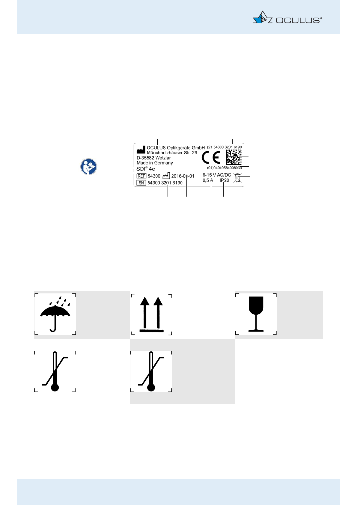
2 Graphic Symbols SDI® 4............................................................................................................2
3 Safety Instructions......................................................................................................................3
3.1 About this Manual .........................................................................................................3
3.1.1 Used Graphic Symbols.................................................................................3
3.2 Safety Instructions for Use..........................................................................................4
4 Proper Use.....................................................................................................................................7
5 Description of the Unit..............................................................................................................8
6 Functional description ...............................................................................................................9
7 Initial Operation ....................................................................................................................... 10
7.1 Preliminary Steps......................................................................................................... 10
7.2 Attach the SDI® 4 to an Operation Microscope ................................................. 10
8 Operation.................................................................................................................................... 13
8.1 Prior to each Use ......................................................................................................... 13
8.2 Practical Tips for Use.................................................................................................. 13
9 Care and Maintenance ...........................................................................................................14
9.1 Removing the Accessories......................................................................................... 14
9.2 Cleaning ......................................................................................................................... 14
9.3 Sterilization of the Rubber Cap............................................................................... 15
10 Transport and Storage ............................................................................................................ 15
11 Troubleshooting........................................................................................................................ 15
12 Guarantee and Service............................................................................................................ 17
12.1 Assumption of Liability for Functions and Damage .......................................... 17
12.2 Manufacturer’s and Service Addresses.................................................................. 18
13 Disposal of Used Devices........................................................................................................ 18
14 Order Information, Accessories and Replacement Parts............................................... 19
15 Technical Data .......................................................................................................................... 20
15.1 Datasheet for plug-in power supply unit GEM12I 09-P1J (54905).............. 23

Table of Contents
iii / iii Instruction Manual SDI® 4 (G/54320/EN 0220 Rev01)

1 Scope of Delivery
Instruction Manual SDI® 4 (G/54320/EN 0220 Rev01) 1 / 24
1 Scope of Delivery
SDI® 4
We reserve the right to make changes to deliverables as a part of any
technical improvements.
Product (versions)
SDI® 4m
with two protective dust covers and transportation lock
54302
SDI® 4m (Leica Version)
with two protective dust covers and transporting lock
54312
SDI® 4e
with two protective dust covers and transportation lock
54300
SDI® 4e (Leica Version)
with two protective dust covers and transportation lock
54310
SDI® 4c
with two protective dust covers and transportation lock
54320
SDI® 4c (Leica Version)
with two protective dust covers and transportation lock
54330
Accessories for each SDI® 4
Sterilisable rubber cap 54335
Hexagon screw driver 05490061
Plastic carrying case with liners
Instruction Manual G/54320/EN/...
Conditioning Instructions G/55185/xxxx/en
Accessories for SDI® 4c and SDI® 4e
For SDI® 4c only: Cable duct usable with steam autoclave 54178
Optional: Plug-in power supply GEM12I 09-P1J 54905
Optional: extension cable for voltage power supply plug
(approx. 5 m)
54898
Required accessories:
Combination foot switch SDI® 4c
Footswitch for SDI® 4e
Optional: extension cable to SDI® 4e foot switch (aprrox. 5 m)
54881
54883
54885

2 Graphic Symbols SDI® 4
2 / 24 Instruction Manual SDI® 4 (G/54320/EN 0220 Rev01)
If transport damage is discovered from the shipment, please file a
complaint with the shipping company immediately.
Have the damage confirmed on the bill of lading so that an orderly
handling of the complaint for damages is possible.
2 Graphic Symbols SDI® 4
Pictograms on the packaging
1 Company logo + manufacturer 8 Power supply
2 CE marking 9 Date of manufacture
3/5 UDI number 10 Serial number of the device
4 Matrix 11 Reference number
6 Disposal in household trash is prohibited
(SDI® 4c and SDI® 4e only
12 Name of device
7 Protection class (SDI® 4c and SDI® 4e only) 13 Heed Instruction Manual
Fig. 2-1: Example: Graphic Symbols SDI® 4e
1
5
6
12
7
9
10
11
23
4
8
13
Keep dry up fragile
Permitted
temperature range
for transport
Permitted
temperature range
for storage
Transport
Storage

3 Safety Instructions
Instruction Manual SDI® 4 (G/54320/EN 0220 Rev01) 3 / 24
3SafetyInstructions
Attention
All safety-related instructions for use of the SDI® 4 are given in the
Instruction Manual for the unit. It is therefore imperative that you read
and understand the whole Instruction Manual before you use the SDI® 4.
3.1 About this Manual
Carefully read through the Instruction Manual.
Make sure to keep the instruction manual in a safe place and
available to operating personnel at all times.
Observe the legal regulations with regard to accident prevention.
3.1.1 Used Graphic Symbols
Attention
Denotes a potentially hazardous situation which can easily result in minor
physical injury or property damage.
Note
Denotes situations which could result in incorrect findings, denotes user
instructions and useful or other important information.
☞
Denotes important information about the product and its use, which
require special attention.

3 Safety Instructions
4 / 24 Instruction Manual SDI® 4 (G/54320/EN 0220 Rev01)
3.2 Safety Instructions for Use
Attention
Risk of personal injury or property damage due to improper operation
Observe the following safety instructions.
Risk of personal injury or property damage due to equipment
modifications that could jeopardize safety
This equipment may not be modified without the permission of the
manufacturer. Changes or modifications may only be made by
OCULUS Service and authorized dealers.
Instructions for operating personnel
Ensure that the SDI® 4 is used only by duly trained physicians and
operating theatre personnel, who, due to their training or their
knowledge and practical experience, can guarantee proper handling
of the device. Only OCULUS or an authorized dealer is allowed to
train the personnel.
Transport and storage instructions
Refer to the notes in sect. 10, page 15.
Instructions for setup and connection
Only OCULUS, an authorized dealer or trained personnel are allowed
to setup and connect the SDI® 4.
Comply with the legal provisions in force in your country, and with
the hygiene and waste disposal regulations of the hospital or clinic.
Set up the SDI® 4 so that the power plug is easy to access. That way,
you can easily disconnect it from the power supply for any repairs or
maintenance work.
Do not use excessive force to plug in the electrical plugs for the
OCULUS BIOM® 5.
If you are unable to make a plug connection, check whether the plug
fits the socket.
If you find damage to the plug connector, have the damage
corrected by our service department.
Heed unconditionally the operating in-structions and safety advice
of the operating microscope and of the additional equipment.
Familiarize yourself with all safety features and devices before you
put the unit into initial operation.

3 Safety Instructions
Instruction Manual SDI® 4 (G/54320/EN 0220 Rev01) 5 / 24
Operation and Maintenance Information
Before initial operation: Let OCULUS or an authorized dealer train
you in the operation of the SDI® 4.
Never operate a damaged SDI® 4. Inform the supplier of any damage.
Only operate the SDI® 4 with the original accessories supplied by us
and only when the unit is in a technically perfect condition.
Only operate the equipment after your have read and understood the
Instruction Manual.
Do not touch the patient and the device at the same time.
If a malfunction occurs that you cannot rectify by following in the
instructions in the troubleshooting table (sect. 11, page 15), you
must not use the device. Clearly mark the unit as non-operational
and get in touch with our service personnel.
The sterilisable rubber cap for the adjusting knob of the SDI® 4 must
be sterilised before the first and before each subsequent use.
It is imperative that you heed the cleaning, disinfection and
sterilisation instructions given in the Conditioning Manual.
A sterilisation of the SDI® 4 is not possible.
Instructions for disassembly and disposal
When disconnecting electrical connections, pull on the respective
plug and not on the cable itself. Take hold of the plug, do not pull on
the cable.
Dispose of the equipment in compliance with the corresponding
legal requirements. Comply with the hygiene and disposal
regulations of the hospital or clinic.
Patient environment information
Patient environment is the area where patients can come into contact
with any part of a medical electrical equipment (ME equipment) or with
another person being in contact with the ME equipment.
In the patient environment, use devices that conform to IEC 60601-1. If
a multiple power socket is to be used, or if a device is to be used that
does not meet the IEC 60601-1 standard, use an isolating transformer.

3 Safety Instructions
6 / 24 Instruction Manual SDI® 4 (G/54320/EN 0220 Rev01)
EMC and Electrical Safety Information
The SDI® 4c, a connected BIOM® 5 and a microscope constitute a Medical Electrical
System (ME System) in accordance with DIN EN 60601-1. If you connect any more
devices, they too become part of the ME System.
Make sure that all devices of the ME System meet the provisions of IEC 60601-1
or of IEC 60950-1
Use the plug-in power supply unit included in the scope of delivery.
Attention
Use of a Multiple Socket Extension Cord
Risk of personal injury or material damage caused by unsafe multiple socket extension
cord
If you use a multiple socket extension cord to connect the SDI® 4 to the power supply,
you must heed the following information:
Use a multiple socket extension cord that complies with the requirements of DIN
EN 60601-1:2005 section 16.
Do not place the multiple socket extension cord on the floor.
Do not use more than one multiple socket extension cord.
Plug only the SDI® 4 into this multiple socket extension cord.
If you use a multiple socket extension cord, it must be supplied with power via an
isolating transformer.
Electromagnetic Compatibility (EMC / Cables)
Risk of personal injury or damage to property due to electromagnetic interference
Portable and mobile HF communications appliances (high frequency) can affect
medical, electric equipment.
Make sure that portable and mobile RF communications equipment do not cause
interference.
Recommendation: Maintain a minimum distance of 4 m. If the distance is shorter,
you must ensure that the SDI® 4 functions correctly.

4 Proper Use
Instruction Manual SDI® 4 (G/54320/EN 0220 Rev01) 7 / 24
4 Proper Use
These stereoscopic diagonal inverters SDI® 4m/4e/4c reverse the picture
of indirect monitoring systems (BIOM® 5, wide-angle contact lenses) true
to side for the human eye during minimal invasive posterior segment
surgery.
The device must only be used by duly trained physicians and operating
theatre personnel, who, due to their training or their knowledge and
practical experience, can guarantee proper handling of the device. Only
OCULUS or an authorized dealer is allowed to train the personnel.
The SDI® 4 is designed for use in hospitals and clinics in conjunction with
the appropriate operation microscopes.
These operation microscopes must have been designated as adaptable by
the company OCULUS Optikgeräte GmbH.
Make certain that the following connection types are used for the
power supply.
Contraindication
not known

5 Description of the Unit
8 / 24 Instruction Manual SDI® 4 (G/54320/EN 0220 Rev01)
5 Description of the Unit
1 Top dust cover 5 Bottom dust cover
2 Transporting lock for star knob 6 Indicator lamp
3 Star knob 7 Connection for a foot switch (optional)
4 SDI® 4e 8 Power supply connection
Fig. 5–1: Unit Components SDI® 4e
1 Top dustcover 6 Indicator lamp
Transporting lock for star knob 7 Connection for a foot switch
3 Star knob 8 Power supply connection
4 SDI® 4c 9 BIOM® 5c connection, pivotable
5 Bottom dust cover
Fig. 5–2: Unit Components SDI® 4c
1
5
2
7
8
3
4
6
1
5
7
82
9
3
4
6

6 Functional description
Instruction Manual SDI® 4 (G/54320/EN 0220 Rev01) 9 / 24
6 Functional description
The SDI® 4 (Stereoscopic Diagonal Inverter) is used to reinvert images, e.g.
that of a BIOM® 5 or a wide angle contact lens.
SDI® 4e/4c
On the SDI® 4e/4c, the image can be inverted by pressing an optional foot
switch.
You can also operate the inverting optics manually with the star knob.
You can recognize the position of the optical system by the indicator
light. If it is illuminated, the optic system and the image inversion feature
are activated.
If adjusting mechanically by hand when the electric power switch is
turned on, turn the star knob clockwise until you feel it click into position.
The indicator lights up shortly before the final position is reached.
For SDI® 4c only
If you are using the SDI® 4c in conjunction with the BIOM® 5c, the image
inversion function is controlled by the position of the BIOM® 5c.
When the BIOM® 5c is swung into the vertical working position, a
position switch on the BIOM® 5c activates the SDI® 4c.
The SDI® 4c is automatically deactivated when the BIOM® 5c is swung
out of the beam path.
Respectively, you can control the SDI® 4c with the combination foot
switch.
SDI® 4m
Image inversion with the SDI® 4m can take place only by mechanical
adjustment with the star knob. You can recognize the position of the
optical system by the indicator in the transparent glass. It is centrally
located on the front of the SDI® 4m, just to the left of the star knob. If
the sight glass is completely yellow, the image erection is not active.

7 Initial Operation
10 / 24 Instruction Manual SDI® 4 (G/54320/EN 0220 Rev01)
7 Initial Operation
Attention
Risk of incorrect use due to improper training
Before initial operation: Let OCULUS or an authorized dealer train you in the
operation of the SDI® 4.
7.1 Preliminary Steps
Remove the plastic carrying case from its packing and dispose of the packing
properly.
Make sure that the sterilisable rubber cap has been cleaned, disinfected and
sterilised before the first and every subsequent use.
Keep the plastic case and the transport lock for the star knob.
If you want to store the SDI® 4 for a longer period of time or if you want to
transport it, or if you have to return it for service or repair, this can only be
optimally done in the plastic case with special insert and with the transport lock
for the star knob.
Like the operation microscope, the SDI® 4 is part of an optical unit. Handle the
equipment with care. Do not expose the equipment to vibrations, knocks, soiling
and high temperatures (above 35°C).
Before assembling the unit, remove both protective dust covers and the
transporting lock for star knob. Keep the two dust covers for proper dust
protection later, in case you have to dismantle the SDI® 4 at some point.
7.2 Attach the SDI® 4 to an Operation Microscope
Always take care when mounting or removing the SDI® 4 that none of the optics
in the beam path become soiled.
1 Locking screw
Fig. 7–1: Before the installation of the SDI® 4
1

7 Initial Operation
Instruction Manual SDI® 4 (G/54320/EN 0220 Rev01) 11 / 24
Whilst protecting the binocular tube from falling down, please
unscrew the locking screw on the main body of the microscope (1).
The SDI® 4 is generally mounted below the beam splitter.
To do so, remove the binocular tube, including the beam splitter from
the body of the microscope.
On some microscopes, the beam splitter is fully integrated into the
microscope, in which case you then have to mount the SDI® 4 above
the beam splitter.
Place the flange of the SDI® 4 into the dovetail receptacle of the
main body of the microscope. Check that the SDI® 4 is properly
seated before carefully tightening the locking screw of the main
body of the microscope. When properly mounted, the SDI® 4 should
not wobble.
Make sure of this before attaching the other microscope
components.
Proceed in the same manner when mounting the beam splitter, the
binocular eyepiece and other components of the microscope;
Carefully tighten the hexagon socket set screw of the SDI® 4 (Fig. 7–
2, page 12, pos. 2) in the same way with the included hexagon screw
driver and then make sure that each component is correctly seated.
Before connecting the electrical versions of the SDI® 4 to the power
supply, check to see whether the power supply voltage is within the
voltage range given on the rating plate.
This is guaranteed if the plug-in power supply unit provided by
OCULUS is used.
Make sure that the voltage supply in the mains socket is within the
voltage range of the plug-in power supply unit.
When connecting the hand or foot switch, please do not join the
electrical plug-and-socket connections by excessive force.
After inserting the plugs into the corresponding sockets (Fig. 7–2,
page 12, items 3 and 4), lock them in place by turning the threaded
connector (milled sleeve).

7 Initial Operation
12 / 24 Instruction Manual SDI® 4 (G/54320/EN 0220 Rev01)
Connector SDI® 4c
Make sure that the plugs are plugged into the appropriate jacks or
sockets.
Plug the plug for the foot switch into the 5-pole jack (3).
Plug the power supply plug (6V-15V) into the 3-pole jack (4).
After plugging in the plug, secure it by turning the screw connectors
(knurled bushings).
If you want to connect the SDI® 4 to a BIOM® 5c: Plug the BIOM®
5c plug into one of the rotating, 4-pole jacks (2).
Caution
The SDI® 4c is connected to the BIOM® 5c solely via the 4-pole jacks (2).
1 Set screw of the SDI® 4 3 Plug for the combination foot switch
2 Connection jack for the BIOM®5 4 Connection jack for power supply
Fig. 7–2: Example: SDI® 4c at the microscope
2
3
4
1

8 Operation
Instruction Manual SDI® 4 (G/54320/EN 0220 Rev01) 13 / 24
8Operation
8.1 Prior to each Use
Before each use, check that
the unit is in technically perfect condition
all connections and fasteners that can be loosened are properly
tightened and are in a safe condition
all cables and plugs are free of damage
the unit is connected to a proper power supply (SDI® 4c and SDI® 4e).
All electric functions are operational:
- SDI® 4 on/off (SDI® 4e and 4c)
- BIOM®-focussing up, BIOM®-focussing down (SDI® 4c)
the rubber covering for the adjustment button of the SDI® 4c is
supplied and sterile.
Adjust the binocular tube to as comfortable a position as possible.
8.2 Practical Tips for Use
To adjust the optical system of the SDI® 4: Briefly press the foot
switch. The optic system then moves to its other position.
Always activate the SDI® 4 if you are using optical inversion, e.g.
BIOM® or an indirect vitrectomy lens.
When the unit is activated, the indicator lamp at the SDI® 4c and
SDI® 4e lights up. The indicator remains empty on the SDI® 4m.
If you are using non-inverting optics, usch as e.g. a Kilp contact lens,
or if you have swung out the BIOM®, you must deactivate the
inverting optics of the SDI® 4. The indicator light of the SDI® 4c and
SDI® 4e is not illuminated in this case, and is yellow on the SDI® 4m
and shows “0“.

9 Care and Maintenance
14 / 24 Instruction Manual SDI® 4 (G/54320/EN 0220 Rev01)
9 Care and Maintenance
Cleaning of the SDI® 4 is described in this chapter.
Disinfection is not necessary.
Sterilisation of the SDI® is not possible; only the rubber cap of the star
knob on the SDI® 4 can be sterilised.
Heed the product descriptions and instruction manuals of products
and equipment you use to care for, clean, and disinfect the unit and/
or its accessories.
9.1 Removing the Accessories
Pull the rubber cap off the star knob.
When disconnecting electrical connections: Do not pull on the cable,
but pull the respective plug or loosen the screw connectors. To do so,
take hold of the respective plug.
To disconnect the hand or foot switch: Loosen the screw connector
of the plug at the connecting cable and pull the plug out of the jack.
9.2 Cleaning
Attention
Risk of electric shock if the SDI® 4 is not completely disconnected from
the power supply for these jobs.
Before cleaning the SDI® 4, disconnect it from the power supply.
Required Materials
Damp cloth (distilled water)
Cleaning intervals
Whenever necessary
Cleaning the Housing
Clean only the exterior surfaces of the unit with a damp cloth.
Do not clean the SDI® 4 with aggressive, chlorine-containing,
abrasive or sharp cleaning agents.
☞
If the protective glasses are dirty, contact OCULUS Service or an
authorized dealer.

10 Transport and Storage
Instruction Manual SDI® 4 (G/54320/EN 0220 Rev01) 15 / 24
9.3 Sterilization of the Rubber Cap
If you are using the rubber cap for the star knob, it must be sterilised first.
The rubber cap for the star knob of the SDI® 4 can be autoclaved with
steam (max. 134°C); also refer to the Conditioning Manual.
10 Transport and Storage
Attention
Equipment damage due to improper transport and storage
Transport the SDI® 4 with care.
Store the SDI® 4 in compliance with the transport and storage
conditions, the national regulations and the regulations of your
hospital. Also see sect. 15, page 20.
Avoid impacts when moving the SDI® 4 to another location, since
this can have an adverse affect on the adjustments.
With the use of the transporting lock for star knob you position the
optical system of the SDI® 4 in the rest position. Only then the
position is fixed.
Check the unit and its accessories for damage after every transport.
11 Troubleshooting
Attention
If a fault occurs which you are unable to correct by following the
instructions below, label the device as “out of order” and contact our
service department. (Address: sect. 12.2, page 18).
Never operate a damaged SDI® 4.

11 Troubleshooting
16 / 24 Instruction Manual SDI® 4 (G/54320/EN 0220 Rev01)
Fault list - SDI® 4
Fault Possible cause Remedy
No function when the hand
switch / foot switch is pressed
(hand-held pushbutton for SDI® 4c
only optional)
The hand switch / foot switch
is not connected to the
SDI® 4e/c
no connection of the SDI® 4e/
c to the power supply
Power failure or power socket
is not active
These are not active if the
sockets of the stand are being
used.
Establish the connection to
the SDI® 4e/c
Establish the connection to
the power supply
Inform the in-house
electrician
Use the plug transformer
Switch the SDI® 4
mechanically
Activate the sockets in
accordance with the
instructions for the stand
Ask the microscope
manufacturer for assistance
The image is cropped The SDI® 4 or other
components are incorrectly
mounted at an angle
The optics of the SDI® 4 are
not in operating position
(locking position)
Correct the assembly
Turn it on or off again with
the switch
Unclear image The SDI® 4 or the optic of the
BIOM® 5 are dirty
Clean the glass surface of the
BIOM® 5 loupe
If the SDI® 4 optics are dirty,
contact OCULUS Service or
your authorized dealer.
The SDI® 4 or its fixtures wobble The locking screws are loose Tighten the locking screws
Fundus view is too narrow Distance between
ophthalmoscopic lens and eye
too large (only when using
BIOM® 5)
Magnification of the
microscope system to high
Carefully reduce the distance
using the microscope fine
adjustment mechanism
Reduce magnification of the
microscope
Pronounced reflections on BIOM®-
loupe or contact lens
The microscope light is on
Bright ceiling illumination
Turn the light off, illuminate
only intraocular
Other manuals for SDI 4
1
This manual suits for next models
9
Table of contents
Other OCULUS Inverter manuals
Popular Inverter manuals by other brands

Sofar
Sofar HYD3000-ES user manual

Bolanmu Energy
Bolanmu Energy xtm 1500-12 quick guide

Vetus
Vetus GHX8 owner's manual

Kostal
Kostal PIKO 4.2 operating manual

Phocos
Phocos Any-Grid Series Setup guide

Assurance Engineering
Assurance Engineering Assuramce Emergency Lighting Si-125 Installation & operation manual

Victron energy
Victron energy 12 3000 120V manual

Advanced Energy
Advanced Energy AE 75TX Installation and operation

Grape Solar
Grape Solar GS-540-KIT Quick connect guide

Weather X
Weather X RPS8807DT instruction manual

Northern Lights
Northern Lights PX-300K1 Series A.C. Generator Operator's & parts manual

Fimer
Fimer T 422 instruction manual