6
ODB COMPANY
800-446-9823 LCT6000
TABLE OF CONTENTS
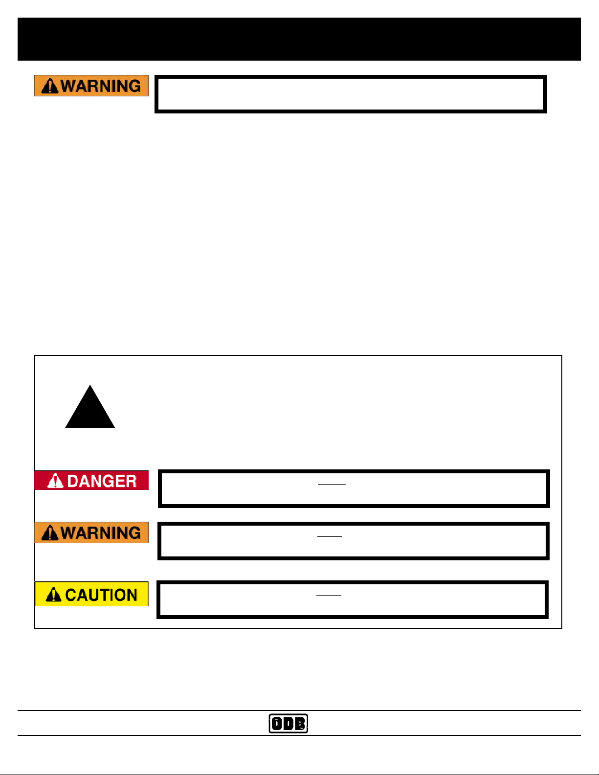
Read and understand this entire manual before operating, maintaining or repairing the leaf
vacuum.
5.4 Impeller Installation and Removal.............................................................................................................. 63
5.4 Impeller Installation and Removal, continued............................................................................................ 64
5.5 Belt Adjustment and Replacement Guide ................................................................................................... 65
5.6 Flange Bearing Installation and Removal................................................................................................... 66
5.6 Impeller Installation and Removal.............................................................................................................. 67
5.7 Replacing the Blower Housing Liners........................................................................................................ 68
5.7 Replacing the Blower Housing Liners; continued,..................................................................................... 69
5.10 WIRING DIAGRAMS
5.10.1 MVP Wiring Diagram............................................................................................................................ 71
5.10.2 Plug Wiring Harnesses........................................................................................................................... 72
5.10.3 Engine Rocker Switch Wiring Diagrams............................................................................................... 73
5.10.4 Trailer Plug Wiring Diagram ................................................................................................................. 74
5.10.5 Trailer Wiring Harness .......................................................................................................................... 75
5.10.6 Brake Wiring Harness ........................................................................................................................... 76
5.10.7 Boom Wiring Diagram........................................................................................................................... 77
5.10.8 Remote Throttle / Clutch Wiring Harness ............................................................................................. 78
5.20 Valve Body Wiring Harness Diagrams
5.20.1 Wiring Harness Diagram 2 Section Valve Body - 2 Axis ..................................................................... 80
5.20.2 Wiring Harness Diagram 4 Section Valve Body - 3 Axis ..................................................................... 81
6.0 ENGINE GROUP
6-0 ..................................................................................................................................................................... 83
6.1 Strobe Light Parts Group ............................................................................................................................ 84
6.2 Battery Group.............................................................................................................................................. 85
6.3 Remote Clutch / Throttle Circuit Board Assembly..................................................................................... 86
6.4 Remote Clutch and Remote Throttle Assembly.......................................................................................... 87
7.0 CLUTCH GROUP
7-0 ..................................................................................................................................................................... 88
7.1 AutoHD PTO Clutch Group........................................................................................................................ 89
7.2 AutoHD PTO Assembly Group .................................................................................................................. 90
7.3 AutoHD PTO Linkage Group ..................................................................................................................... 91
7.4 Clutch Assist Group .................................................................................................................................... 92
7.5 Kraft Fluid Drive Group (Optional)............................................................................................................ 93
7.6 Kraft Fluid Drive Installation (Optional).................................................................................................... 94
7.7 Kraft Fluid Drive Breakdown (Optional) ................................................................................................... 95
7.8 Kraft Fluid Drive Common Parts (Optional).............................................................................................. 96
8.0 BLOWER HOUSING GROUP
8-0 ..................................................................................................................................................................... 97
8.1 Blower Housing Group............................................................................................................................... 98
8.2 Blower Housing Face Group - LCT6000.................................................................................................... 99
8.3 Belt Drive Assembly ................................................................................................................................. 100