PRINTER PAPER
The M35P uses standard 2.25 inch wide plain adding machine tape. The
M35P has an internal box to contain a small roll
of
paper
in
stead
of
using the
external rack to hold a large roll. It's
mu
ch easier to transport and use at the
range. Several portable calculators
us
e these small rolls, but it is much
easier to find the standard large rolls. You can easily make four or five
small rolls from one inexpensive large roll. Simply strip five arm-spans
(twenty-five or thirty feet)
of
paper tape from the big roll, roll it up tightly,
and snap a rubber band around it.
The
paper
will feed into
the
printer
easier
if
you
square
the
end
with scissors and
cut
a half-inch triangle
from each
corner.
Repeat until the big roll
is
gone and you will have a
good supply
of
paper in small rolls.
If
you think this
is
a nuisance, just look
for thermal paper when you buy your roll
of
plain adding machine tape at a
local store. Plain paper is inexpensive, readily available, and the printing
does not disappear with age.
To load the paper tape into the M35, remove the wire clip at the back
of
the
paper box. Plug in the start screen to tum on the M35. Feed the cut end
of
the paper tape into the printer slot at the back
of
the paper box and
pu
sh any
button to generate paper-feeds. The paper feeds best from the top
of
the roll.
After the paper threads through the printer, place the roll
in
the paper box and
replace the wire retainer clip.
If
the printer ink roller gets dry and the print
is
too dim, replace the ink roller.
Many battery-operated portable calculators use the same print mechanism.
Take your ink roller along to your local office supply store and ask for a
roller
to
fit a hand-held calculator. They are usually available and will often
be labeled PR-40 or similar. Ifyou can't find the roller locally, a scant drop
of
stamp-pad ink applied to the foam roller will work. Lacking stamp-pad
ink, you can always try a light mist
of
WD-40 on the foam roller.
If
all else
fails, call Oehler to order a replacement.
A full big roll
of
paper can be mounted externally with the included wire
bracket. To mount the bracket, start with the straightest end
of
the wire
bracket inside the paper box. Twist and feed the bracket through the side
hole until the straight end forms an
ex
ternal hanger for a paper roll. Hook the
crooked end
of
the wire thro
ugh
the small hole previously used for the paper-
retainer clip. Save the paper retainer clip
in
case you want to again use the
smaller rolls.
Page
14
I
I
I
\
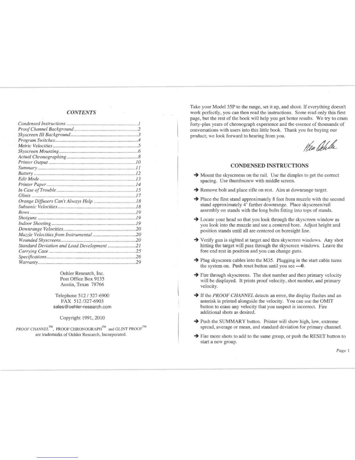
IN CASE
OF
TROUBLE
If
the display does not change when you shoot, it means that no start signal
was received. Pos
si
ble causes are the bullet pas
si
ng too near the top
or
side
of
the skyscreen window, the orange diffuser not being directly illuminated
by the sun, the skyscreen not having an unobstructed view
of
the sky
overhead,
or
having too little light for proper skyscreen operation. Make a
deliberate effort to shoot through the middle
of
the triangular window
of
the
Skyscreen III. Shoot airguns and arrows approximately one-third
of
the way
up the window. Be sure the skyscreen cables are plugged firmly into the
jacks on the back
of
the M35;
if
you can see a band
of
metal between the
plug handle and the jack, it's not plugged in good.
A display
of
--4)
has special significance; the chronograph
is
reset and no
shot has been recognized.. The similar display
of
---- shows that the M35
received a start signal, but didn't get a stop signal corresponding to a
legitimate velocity, and
is
anticipating the next shot. You will get this
display
if
you have the cable from the stop screen plugged into the start
input,
if
the start screen receives a stray input signal before a shot is fired,
if
the stop screen isn't plugged in, or
if
the stop screen doesn't see the bullet.
You can test individual skyscreens
by
plugging only one screen into the
START input. With a good skyscreen, the display should go to
--4)
when
you plug it in, remain at
--4)
until you shoot a
BB
or 22, and then change
to -----when you shoot and the skyscreen sees the bullet.
The printout
of
9999 indicates that the M35 received a start signal and then a
quick stop signal so that the velocity was higher than 9999. You are most
likely to get this printout between actual shots if there
is
severe electrical
noise in the area.
If
the printout shows either ----, 0000
or
9999, you don't
have to push the OMIT button. The unit knows the velocity is wrong and it's
automatically omitted from the summary.
If
the M35 displays a velocity before you shoot,
it
was probably caused by
static electricity. Skyscreens are sensitive to the same electrical noises that
cause static on an AM radio. Typical causes are synthetic clothing
in
dry
weather, nearby high-voltage power lines, large appliances with electrical
motors or solenoids turning on or off, electric fences, or radar and radio
transmitters. Muzzle blast from adjacent benches can also trigger the
skyscreens.
Pag
e
15