Casio QW-4343 User manual

SERVICE MANUAL
& PARTS LIST
(WITHOUT PRICE)
QW-4343
MODULE NO.
R
REF. NO. S/M-981
JAN. 2007
GS-1000J

CONTENTS
Page
1. SPECIFICATIONS: MODULE QW-4343 .................................................... 1
2. DRAWINGS: MODULE QW-4343
2-1. CHECKING TERMINALS AND COMPONENTS ..........................................2
3. EXPLODED VIEW: MODULE QW-4343 .................................................... 3
4. PARTS LIST: MODULE QW-4343 ............................................................. 4
5. PRECAUTIONS FOR REPAIR: MODULE QW-4343
5-1. AC (ALL CLEAR) AND REMOVING OF MODULE ......................................6
5-2. ACCURACY CHECKING,
SOLAR CELL-PCB ASS'Y CONTACT CHECKING.....................................7
5-3. DATE INDICATOR MOVEMENT ACCURACY CHECK MODE ...................8
5-4. TIME CALIBRATION SIGNAL TEST MODE ................................................8
5-5. HANDLING INSTRUCTIONS TO PRESS FITTING THE HANDS...............10
6. TROUBLESHOOTING: MODULE QW-4343............................................. 11

— 1 —
1. SPECIFICATIONS: MODULE QW-4343
Battery CTL1025 (Storage battery)
Note: Use CTL1025 only. Other storage battery or CR1025 can cause
damage to the watch.
Battery life Approx. 5 months
Current consumption 0.40 µA maximum
Alarm system Piezo plate on Cover/Back
Accuracy ±20 sec./month
Accuracy setting system Chip capacitor selection
Accuracy checking See page 7
Functions • Solar powered
• Time calibration signal reception
Auto receive
Manual receive
• Time Calibration Signal
Receivable Time Calibration Signals
Fort Collins, Colorado (Call Sign: WWVB, Frequency: 60kHz)
Fukushima, Japan (Call Sign: JJY, Frequency: 40kHz)
Fukuoka/Saga, Japan (Call Sign: JJY, Frequency: 60kHz)
• Low battery warning display
• World Time
• 1/20-second stopwatch
Measuring capacity: 23:59'59
• Daily alarm
• Power Saving (Turns off the display when the watch is left in the dark)
• Auto-calendar
Item Detail

— 2 —
2. DRAWINGS: MODULE QW-4343
2-1. CHECKING TERMINALS AND COMPONENTS
Short pad for R trimming
2. PCB ASS'Y
(76409259)
VDD2
KI3
O5
O1
O1
O6
GND VSC
XTB
XT
O1
O2
LL1
GND
O1
O3
O1
O4
KI4
KI2
KI1
GND
VDD2
FET-D
P2
KI7
GND
KI2
KI4 KI1
KI3
GND
VSC
VDD2 VSC
AC GND VHF
O6
O5
VCH
GND
VC3
VC4
KC1
VPM RPM
GND
KC4 RPM
VCH
VC3
O1
P7P5
P5
P7 P7
P4
GND
Vcc
Ccp
P9
Ccp
GND
GND
KI8
P3-1
VDD2
GND
VDD2
GND
KI6
R3
KI5
GND
GND
R2
R1 GND
GND
LL1
Tr1 VDD2
VDD2
LL1
LL1
GND
Tr1
BD
SCIN SCIN
SCIN
SCR
GND
GND
GND
GNDB GND GND
XT
XT
VSC
FET-S
FET-S'
FET-S' FET-S'
FET-S'
P2'
P2' P2'
P1' P1' P1' P1' P1' P1'
P2
P2'
P1
P1'
P2'
P1'
Short pad for switching modules
KI5-GND: Open (No Soldering)
KI6-GND: Open (No Soldering)
KI7-GND: Open (No Soldering)
OSCILLATOR/CRYSTAL
CUSHION 506
TAPE/ADHESIVE 2306

—3 —
3. EXPLODED VIEW: MODULE QW-4343
15 (72270294)
14 (72240990)
8 (10212760)
12 (10212759)
4 (10195754)
5 (10212752)
9 (10234346)
9 (10234346)
17 (10209136)
11 (10212761)
3 (10135068)
Battery storage (CTL1025)
7 (10140782)
10 (10135066)
13 (10184045)
2 (76409259)
PCB Ass'y
6 (10218649)
16 (72270343)
1 (76409230)

4. PARTS LIST: MODULE QW-4343
QW-4343YC
1 QW-4343YC-02TK
Note: 1. Prices and specifications are subject to change without prior notice.
2. Spare parts are classified as follows according to their importance in after-sales service.
A ank -----------------------------------------
-
Important
C ank ----------------------------------------- Not Important
3. Batteries in Bulk pack on the tray will be supplied from our Overseas Spare Parts Section under charge basis.
Batteries in Blister pack will be supplied from our Sales Department.
4. As for order/supply of spare parts, refer to the separate publication "GUIDE BOOK for spare parts supply".
Attention to order
1. The most of normal re
p
air or initial re
p
air within 1
y
ear since released month can be done b
y
main
p
arts.
2. Minor
p
arts should be ordered carefull
y
in consideration of the actual usa
g
e of
y
our re
p
air and
y
our technical skills.
3. Main
p
arts should be ordered and stocked a
pp
ro
p
riatel
y
in consideration of
y
our
p
arts usa
g
e anre re
p
air usa
g
e for
similar models.
MAIN PARTS
Item Co e No. Parts Name S
p
ecification Q’TY R
1
76409231 MODULE/WITH MOVEMENT QW-4343YC-02TK 1 A
1 76409230 ANALOG BLOCK QW-4343MV-83TK 1 A
2 76409259 PCB ASS’Y JQ528910*001V01TK 1 A
MINOR PARTS
Item Co e No. Parts Name S
p
ecification Q’TY R
1
3 10135068 BATTE Y/STO AGE CTL1025 1 C
4 10195754 CUSHION 3707-2 JQ524197-001V03 1 C
5 10212752 CUSHION 4323-1 JQ527451-001V01 1 C
6 10218649 HOLDE 4329 JQ527343-001V02 1 C
7 10140782 LABEL JQ517198-001V02 1 C
8 10212760 PLATE/TE MINAL JQ527344-002V01 1 C
9 10234346 SC EW/FLAT 4329 JQ532242-001V01 6 C
10 10135066 SHEET/INSULATION JQ515074-001V01 1 C
11 10212761 SP ING/COIL JQ527345-001V01 2 C
12 10212759 SP ING/LEAF JQ527210-001V01 1 C
13 10184045 TE MINAL/BATTE Y
(
+
)
JQ519936-001V03 1 C
14 72240990 WASHE 388 Q424901-1 1 C
15 72270294 WASHE /745 Q436294A-1 1 C
Notes: Q - Used quantity
- ank
A : Important
C: Not Important
- 4 -

Item Co e No. Parts Name Specification Q’TY R
1
16 72270343 WASHE 1325 Q450447-1 1 C
17 10209136 WHEEL/HOU JQ527061 1 C
For the prices and minimum order/supply quantities of the above parts, refer to the Parts Price List P.P.L.-638.
Notes: Q - Used quantity
- ank
A : Important
C: Not Important
- 5 -

—6 —
5. PRECAUTIONS FOR REPAIR: MODULE QW-4343
5-1. AC (ALL CLEAR) AND REMOVING OF MODULE
1. Perform AC (ALL CLEAR) when inserting a new battery, or else the memories and/ or counters may give
erratic displays.
Touch the AC contact and the main plate with the metallic tweezers.
The contact should be made for about two seconds.
2. On removing of the module from the case, please insert the precision screw driver between the module
and the case pointed by arrows.
Note:After performing AC(ALL CLEAR), the mode is switched to the second hand movement accuracy
check mode at the home position adjustment mode.
Metallic tweezers

—7 —
3. Operation after AC
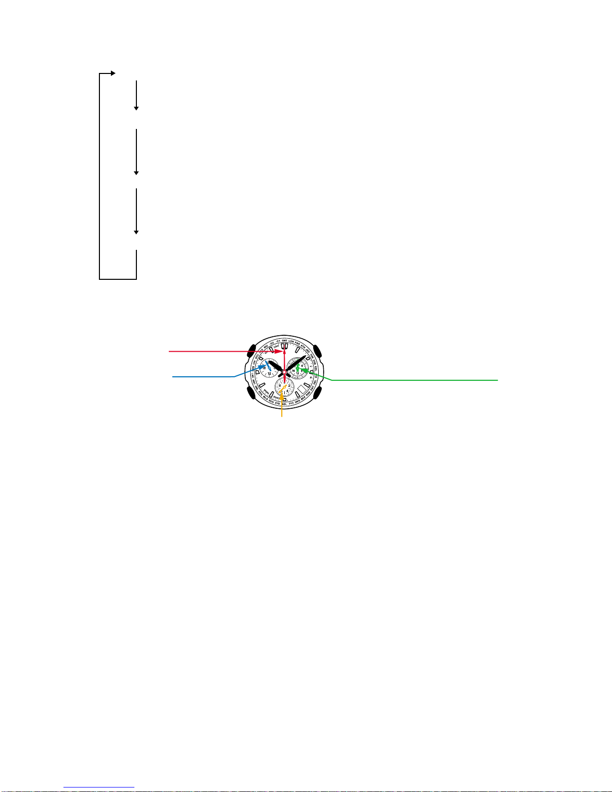
Set the second hand and the indicator hand
Set the second hand with D(fast forward available), set the indicator hand with B(fast
forward available)
Set the hour and minute hands and the 24-hour hand
Dfor normal rotation (fast forward available), Bfor reverse rotation (fast forward available)
*When choosing reverse rotation, go some pulse over your setting position, and then adjust
choosing normal rotation. (Considering backlash)
Set the chronograph hour and minute hands
Dfor normal rotation (fast forward available), Bfor reverse rotation (fast forward available)
*When choosing reverse rotation, go some pulse over your setting position, and then adjust
choosing normal rotation. (Considering backlash)
Adjust the calendar.
Dfor normal rotation (fast forward available), Bfor reverse rotation (fast forward available)
Be sure the measure of the date indicator, "1" is in the frame.
(Try to set it as center as possible.)
Press Ato go back to the noemal timekeeping mode. (It will move to the current time counting from
the AC moment as 00 hour 00 minute.)
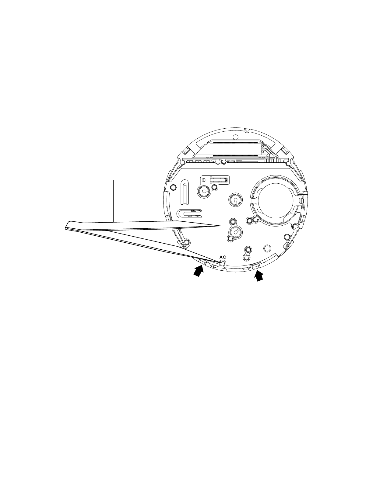
C
C
C
4. How to measure consumption current
This model starts correct positioning of the second hand in the H-SET mode immediately after AC.
When it is functioning, the value of consumption current would be a little higher as the internal circuit
operation would be different from the usual status.
To measure a correct consumption current value, operate as follows.
Hold down Dand turn on the AC, and then let Dgo.
*After the operation above is finished, measure within one minute.
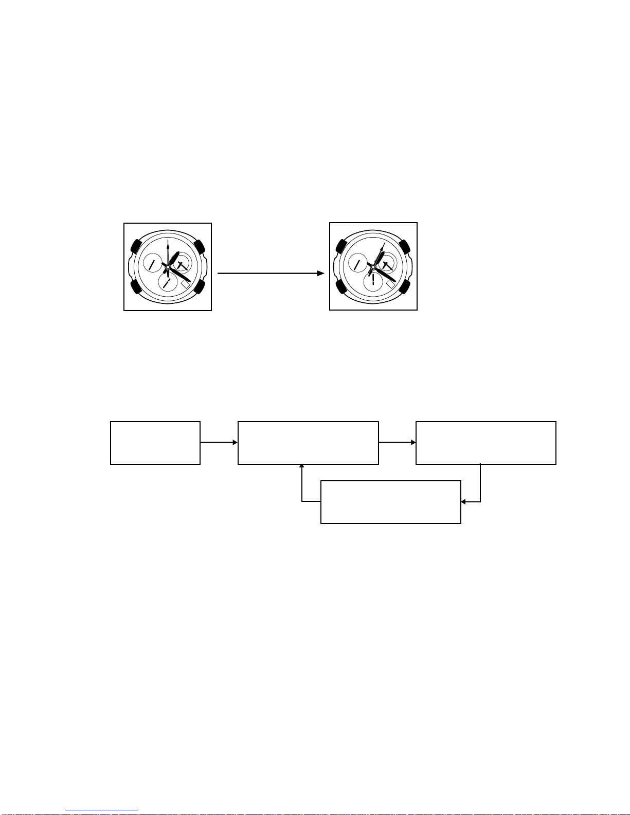
5-2 ACCURACY CHECKING, SOLAR CELL-PCB ASS'Y CONTACT CHECKING
1) From the time mode, hold down Aand press D+ C. The indicator hand moves to 0-second
position.
2) Press Dbutton at the accuracy checking mode (only the second hand in operation.)
3) Press Dbutton at the solar cell-PCB ass’y contact mode (The indicator hand bright: 40 seconds,
dark: 55 seconds)
4) Any key to return to the normal timekeeping mode.
30
Indicator hand
24-hour hand
Second hand
Chronograph hour and minute hands
A
C
B
D

—8 —
A
C
B
D
5-3 DATE INDICATOR MOVEMENT ACCURACY CHECK MODE
1) From thetimemode, holdtogetherin orderof A→B→C.Thedate indicatorandall handsreverse
to the baseline position. (Date is 1st.)
2) After moving to the baseline position, the date indicator circles once in a clockwise direction by
pressing D.
3) After the date indicator is stopped, press any key except for Dto go back to the normal timekeeping
mode.
5-4 TIME CALIBRATION SIGNAL TEST MODE
1) To operate the receiving test, do as follows.
2) From the display prioritized receiving station mode, a test receiving station changes as below every
time Dis pressed.
Time mode Display prioritized receiving station state
The indicator hand at 4-second position: JJY40
6-second position: JJY60
8-second position: WWVB
Hold Adown and
press Dand B
simultaneously.
Display priori-
tized receiving
station state
JJY40 chosen state
(the indicator hand at 55-
second position)
JJY60 chosen state
(the indicator hand at 50-
second position)
WWVB chosen state
(the indicator hand at 45-
second position)
DD
D
D

—9 —
3) From the choice of a receiving station state, press Ato start the test receiving.
*Be sure to confirm the indicator hand moves to 33-second (READY).
4) After about 15 minutes, take a look at the display. Refer to the pictures below to inspect the state
with the position of your indicator hand.
Button positions
When received When not received
JJY40
JJY60
WWVB
5-second
position
10-second
position
15-second
position
55-second
position
50-second
position
45-second
position
A
C
B
D

—10 —
5-5 HANDLING INSTRUCTIONS TO PRESS FITTING THE HANDS
When you need to press hands into place in case of maintenance and other occasions, follow the
instruction below to adjust the polarity of the rotor wheel and the positions of the hands.
1) Press the 24-hour hand and the 3H side hour hand into place near the position of 23H.
2) Drive the 3H side hour hand to a little before the 24H position using normal rotation.
Operation: AC →Press C×2 →Adjust with D
3) While adjusting the polarity of the 3H side minute hand, position the 3H side hour hand precisely
at the 24H position
Operation: AC →Press C×2 →Keep holding down D×2 each time (even number times) to set
the 3H side hour hand.
4) Press fit the 3H minute hand. (Press fit within ±1°as a guide.)
5) Adjust the polarity of the second hand and then press fit the second hand. (Press fit within ±1°as
a guide.)
Operation: AC →Press D×2
6) Position the 24H hour hand precisely at the 24H position using normal rotation.
Operation: AC →Press C×1 →Adjust with D
7) Press fit the hour hand into the 12H position.
8) Reverse the hour hand about 30 minute, and then drive the hand precisely at the 12H position using
normal rotation.
Operation: AC →Press C×1 →Reverse with B→Adjust with D
9) Press fit the minute hand into the 12H position.
10) Adjust the polarity of the indicator hand.
Operation: AC →Press D×2
11) Press the indicator hand into the 12H position. (within ±1°)
How to check the polarity adjustment (one example)
After setting each hand to the baseline positions with H-SET, turn on the AC.
* When pressing Dfor the first time, the second hand moves.
* When pressing Bfor the first time, the second hand moves.
* After pressing C×2, the indicator hand moves when Dis pressed for the first time.

—11 —
6. TROUBLESHOOTING: MODULE QW-4343
This is a flow chart about signal reception.
Yes
No
Yes
No
Yes
No
START
Check whether the Home City
code is selected correctly.
To perform MANUAL time
calibration signal reception
OK
There is a possibility of location bad.
To perform AUTO time
calibration signal reception
Replace the PCB ass'y
Signal
reception OK?
Signal
reception OK?
Signal
reception OK?
OK
OK

CASIO COMPUTER CO.,LTD.
Overseas Service Division
6-2, Hon-machi 1-Chome
Shibuya-ku, Tokyo 151-8543, Japan
This manual suits for next models
1
Table of contents
Other Casio Watch manuals

Casio
Casio 2763 User manual

Casio
Casio 1856 Configuration guide

Casio
Casio 3063 User manual

Casio
Casio IC-02 User manual

Casio
Casio 5141 User manual

Casio
Casio MA1410-EC User manual

Casio
Casio 3736 User manual

Casio
Casio 5446 User manual

Casio
Casio 1949 User manual

Casio
Casio DBC310-1 - DataBank Men's Watch User manual