2
Operating Instructions and Parts Manual 24359
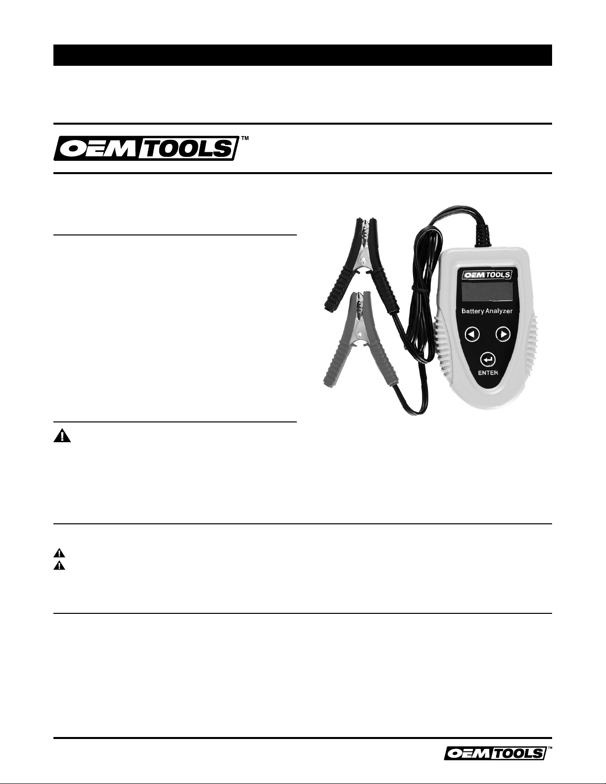
DIGITAL BATTERY ANALYZER
4/18
2018 OEMTOOLS™
IMPORTANT INSTRUCTIONS
AND SAFETY RULES
1. Know your tool. Read this manual carefully. Learn
the tool’s applications and limitations, as well as,
potential hazards specific to it.
2. Keep work area clean and well lit. Cluttered or
dark work areas invite accidents.
3. Keep children away. All children should be kept
away from the work area. Never let a child handle
a tool without strict adult supervision.
4. Do not operate this tool if under the influence
of alcohol or drugs. Read warning labels on
prescriptions to determine if your judgment or
reflexes are impaired while taking drugs. If there is
any doubt, do not attempt to operate.
5. Use safety equipment. Eye protection should
be worn at all times when operating this
tool. Use ANSI approved safety glasses.
Everyday eyeglasses are NOT safety glasses.
Dust mask, non-skid safety shoes, hard
hat or hearing protection should be used in
appropriate conditions.
6. Wear proper apparel. Loose clothing, gloves,
neck-ties, rings, bracelets or other jewelry may
present a potential hazard when operating this
tool. Keep all apparel clear of the tool.
7. Don’t overreach. Keep proper footing and balance
at all times when operating this tool.
8. Check for damage. Check your tool regularly.
If part of the tool is damaged it should be
carefully inspected to make sure that it can
perform its intended function correctly. If in
doubt, the part should be repaired. Refer all
servicing to a qualified technician. Consult
your dealer for advice.
9. Keep away from flammables. Do not attempt
to operate this tool near flammable materials
or combustibles. Failure to comply may cause
serious injury or death.
10. Store idle tools out of the reach of children and
untrained persons. Tools may be dangerous in the
hands of untrained users.
11. Maintain tools with care.
12. Keep tools dry and clean.
13. Properly maintained tools are less likely to
bind and are easier to control. Do not use a
damaged tool. Tag damaged tools “Do not use”
until repaired.
14. Check for misalignment or binding of moving
parts, breakage of parts, and any other condition
that may affect the tool’s operation.
15. If damaged, have the tool serviced before
using. Many accidents are caused by poorly
maintained tools.
16. Use only accessories that are recommended by
the manufacturer for your model. Accessories
that may be suitable for one tool may become
hazardous when used on another tool.
17. Tool service must be performed only by qualified
repair personnel. Service or maintenance
performed by unqualified personnel could result in
a risk of injury.
18. When servicing a tool, use only identical
replacement parts. Use of unauthorized parts or
failure to follow maintenance instructions may
create a risk of injury.
19. Maintain a safe working environment. Keep the
work area well lit. Make sure there is adequate
surrounding workspace. Keep the work area
free of obstructions, grease, oil, trash, and other
debris. Do not use this product in a damp or wet
location.
20. Maintain labels and nameplates on this product.
These carry important information. If unreadable or
missing, contact OEM for a replacement.
21. Keep the tool dry, clean, and free from brake fluid,
oil, and grease.
22. Before use, read and understand all warnings,
safety precautions, and instructions as outlined
in the vehicle manufacturer’s service manual. It
is beyond the scope of this manual to properly
describe the correct procedure and test data for
each vehicle.
23. Always perform vehicle service in a properly
ventilated area. Never run an engine without
proper ventilation for its exhaust. Stop work
and take necessary steps to improve ventilation
in the work area if you develop momentary
eye, nose, or throat irritation as this indicates
inadequate ventilation.
24. Engine parts that are in motion and unexpected
movement of a vehicle can injure or kill. When
working near moving engine parts, wear snug fit