OEM Tools 24369 Service manual

UNPACKING
After unpacking unit, inspect
carefully for any damage that
may have occurred during transit.
Check for loose, missing, or
damaged parts. If any damage
is observed, a shipping damage
claim must be filed with carrier.
Do not use Battery Tester if
broken, bent, cracked or damaged
parts (including labels) are noted.
Any Battery Tester that appears
damaged in any way, operates
abnormally or is missing parts
should be removed from service
immediately. If you suspect that
the Digital Battery Analyzer was
subjected to a shock load (a
load that was dropped suddenly,
unexpectedly, etc.) immediately
discontinue use until it has been
checked by a factory authorized
service center.
Please read and save these instructions. Read through this owner’s manual carefully before using product. Protect
yourself and others by observing all safety information, warnings, and cautions. Failure to comply with instructions
could result in personal injury and/or damage to product or property. Please retain instructions for future reference.
Operating Instructions and Parts Manual 24369
05/15
2015 ©OEMTOOLS
FOR CUSTOMER SERVICE
Technical Question?
CALL 1-866-458-2472
DIGITAL BATTERY
ANALYZER
Explanation of Safety Signal Words
CAUTION
WARNING
The following safety information is provided as guidelines to help you operate your Digital Battery Analyzer under the safest
possible conditions. Any tool or piece of equipment can be potentially dangerous to use when safety or safe handling
instructions are not known or not followed. The following safety instructions are to provide the user with the information
necessary for safe use and operation. Please read and retain these instructions for the continued safe use of your service
system. Failure to follow instructions listed below may result in serious injury. In addition, make certain that anyone that uses
the equipment understands and follows these safety instructions as well.
WARNING
: Indicates a potentially hazardous situation which, if not avoided, could result in death or serious injury.
: Indicates a potentially hazardous situation which, if not avoided, may result in minor or moderate injury.
: Used without the safety alert symbol indicates a potentially hazardous situation which, if not avoided,
may result in property damage.
: Provide clarity and helpful information.
CAUTION
Notes

2
Operating Instructions and Parts Manual 24369
DIGITAL BATTERY
ANALYZER
Thank you very much for choosing an OEMTOOLS
Product!
For future reference, please complete the owner’s
record below:
Model: _______________ Purchase Date: _______________
Save the receipt, warranty and these instructions. It is
important that you read the entire manual to become
familiar with this product before you begin using it.
This machine is designed for certain applications
only. OEMTOOLS cannot be responsible for issues
arising from modification. We strongly recommend
this machine is not modified and/or used for
any application other than that for which it was
designed. If you have any questions relative to a
particular application, DO NOT use the machine until
you have first contacted OEMTOOLS to determine if
it can or should be performed on the product.
For technical questions please call 1-866-458-2472.
IMPORTANT INSTRUCTIONS
AND SAFETY RULES
1. Know your tool. Read this manual carefully. Learn
the tool’s applications and limitations, as well as,
potential hazards specific to it.
2. Keep work area clean and well lit. Cluttered or dark
work areas invite accidents.
3. Keep children away. All children should be kept
away from the work area. Never let a child handle
a tool without strict adult supervision.
4. Do not operate this tool if under the influence
of alcohol or drugs. Read warning labels on
prescriptions to determine if your judgment or
reflexes are impaired while taking drugs. If there is
any doubt, do not attempt to operate.
5. Use safety equipment. Eye protection should
be worn at all times when operating this tool.
Use ANSI approved safety glasses. Everyday
eyeglasses are NOT safety glasses. Dust mask,
non-skid safety shoes, hard hat or hearing
protection should be used in appropriate
conditions.
6. Wear proper apparel. Loose clothing, gloves,
neckties, rings, bracelets or other jewelry may
present a potential hazard when operating this
tool. Keep all apparel clear of the tool.
7. Don’t overreach. Keep proper footing and balance
at all times when operating this tool.
8. Check for damage. Check your tool regularly. If
part of the tool is damaged it should be carefully
inspected to make sure that it can perform its
intended function correctly. If in doubt, the part
should be repaired. Refer all servicing to a qualified
technician. Consult your dealer for advice.
9. Keep away from flammables. Do not attempt
to operate this tool near flammable materials
or combustibles. Failure to comply may cause
serious injury or death.
10. Store idle tools out of the reach.
11. Maintain tools with care.
12. Keep tools dry and clean.
13. Properly maintained tools are less likely to bind
and are easier to control. Do not use a damaged
tool. Tag damaged tools “Do not use” until
repaired.
14. Check for misalignment or binding of moving
parts, breakage of parts, and any other condition
that may affect the tool’s operation.
15. If damaged, have the tool serviced before using.
Many accidents are caused by poorly maintained
tools.
16. Use only accessories that are recommended by
the manufacturer for your model. Accessories
that may be suitable for one tool may become
hazardous when used on another tool.
17. Tool service must be performed only by qualified
repair personnel. Service or maintenance
performed by unqualified personnel could result in
a risk of injury.
18. When servicing a tool, use only identical
replacement parts. Use of unauthorized parts or
failure to follow maintenance instructions may
create a risk of injury.
19. Maintain a safe working environment. Keep the
work area well lit. Make sure there is adequate
surrounding workspace. Keep the work area free
of obstructions, grease, oil, trash and other debris.
Do not use this product in a damp or wet location.
20. Maintain labels and nameplates on this product.
These carry important information. If unreadable
or missing, contact OEM for a replacement.
21. Keep the handle dry, clean and free from brake
fluid, oil and grease.
05/15
2015 ©OEMTOOLS

3
Operating Instructions and Parts Manual 24369
DIGITAL BATTERY
ANALYZER
22. Before use, read and understand all warnings,
safety precautions and instructions as outlined
in the vehicle manufacturer’s service manual. It
is beyond the scope of this manual to properly
describe the correct procedure and test data for
each vehicle.
23. Always perform vehicle service in a properly
ventilated area. Never run an engine without
proper ventilation for its exhaust. Stop work and
take necessary steps to improve ventilation in the
work area if you develop momentary eye, nose
or throat irritation as this indicates inadequate
ventilation.
24. Engine parts that are in motion and unexpected
movement of a vehicle can injure or kill. When
working near moving engine parts, wear snug fit
clothing and keep hands and fingers away from
moving parts. Keep hoses and tools clear of
moving parts. Always stay clear of moving engine
parts. Hoses and tools can be thrown through
the air if not kept clear of moving engine parts.
The unexpected movement of a vehicle can injure
or kill. When working on vehicles always set the
parking brake or block the wheels.
25. Avoid accidental fire and/or explosion. Do not
smoke near engine fuel and battery components.
26. The warnings, precautions and instructions
discussed in this manual cannot cover all possible
conditions and situations that may occur. The
operator must understand that common sense and
caution are factors which cannot be built into this
product, but must be supplied by the operator.
27. For safety purposes and the prevention of damage
to expensive components it is advised that the
user have an understanding of basic automotive
repair and a working knowledge of automotive
systems.
28. We believe the information contained herein to be
reliable. However, general technical information
is given by us without charge and the user shall
employ such information at his own discretion and
risk. We assume no responsibility for results or
damages incurred from the use of such information
in whole or in part. Always refer to specific
instructions and technical information supplied by
vehicle manufacturer.
29. The manufacturer declines any and all
responsibility for damage to vehicles or
components if said damage is the result of
unskillful handling by the operator or of failure
to observe the basic safety rules set forth in the
instruction manual.
DISPOSAL
At the end of the useful life of the Digital Battery
Analyzer, dispose of the components according to all
state, federal, and local regulations.
PURPOSE
A safe, fast, simple and portable Battery, Starting and
Charging System Analyzer.
05/15
2015 ©OEMTOOLS
Battery CCA 40 - 2,000
Voltage Testing Range 1.5 - 15VDC
Maximum Power
Consumption .5W
Operating Temperature 14º - 122º Fahrenheit
Testing Standards SAE, DIN, EN, IEC, CA
PRODUCT SPECIFICATIONS

4
Operating Instructions and Parts Manual 24369
DIGITAL BATTERY
ANALYZER
Always wear safety glasses and gloves!
OPERATING INSTRUCTIONS
• WORKING NEAR A LEAD ACID BATTERY IS DANGEROUS. BATTERIES CAN GENERATE EXPLOSIVE
GASES DURING NORMAL OPERATION. BATTERY EXPLOSION CAN KILL, INJURE AND CAUSE
PROPERTY DAMAGE! TO REDUCE RISK OF BATTERY EXPLOSION, READ THE FOLLOWING OPERATING
INSTRUCTIONS AND THOSE PUBLISHED BY THE BATTERY MANUFACTURER AND THE PREVIOUS
SAFETY INSTRUCTIONS PRIOR TO OPERATING THIS TESTER.
• RISK OF CONTACT WITH BATTERY ACID. BATTERY ACID IS A HIGHLY CORROSIVE SULFURIC ACID.
• BE SURE AREA IS WELL VENTILATED WHILE THE BATTERY IS BEING TESTED.
• WHEN WORKING NEAR THE BATTERY, PLEASE MAKE SURE THERE ARE OTHERS AROUND WHO CAN
PROVIDE HELP IF NEEDED.
• PLEASE BE READY WITH WATER AND SOAP NEAR YOU, IN CASE BATTERY ACID COMES INTO CONTACT
WITH SKIN, CLOTHES OR EYES.
• PLEASE WEAR PROTECTION AND SAFETY EQUIPMENT.
WARNING
05/15
2015 ©OEMTOOLS
Figure Description Quantity
24368A Positive Battery
Clamp (Red) 1
24368B Negative Battery
Clamp (Black) 1
24368C Lead Set 1
24368D Menu Button 1
24368E Increase Button 1
24368F Decrease Button 1
24368G Display 1
24369H Battery Cover
(Not Shown)
1
(A)
Positive Battery
Clamp (Red)
(B)
Negative Battery
Clamp (Black)
(C)
Lead Set
(D)
Menu Button
(E)
Increase
Button
(F)
Decrease
Button
(G)
Display

5
Operating Instructions and Parts Manual 24369
DIGITAL BATTERY
ANALYZER
• IF BATTERY ACID COMES INTO CONTACT WITH
SKIN OR THE CLOTHES, IMMEDIATELY WASH
WITH SOAP AND WATER. IF THE BATTERY ACID
GETS INTO EYES, RINSE EYES WITH WATER
RIGHT AWAY FOR AT LEAST 10 MINUTES THEN
GO TO THE HOSPITAL.
• This equipment is intended only for professional
use by personnel trained in performing the service
functions for which it is has been designed.
• This equipment is designed for servicing a variety
of vehicles in a safe, convenient manner. However,
differences in vehicle makes and models may make
it impossible to use this equipment as it is intended.
Do not attempt to force the use of this equipment
on an application for which it is not designed to
perform.
• The procedures documented in this manual are to
serve as guidelines for the use of this equipment.
• In addition to these guidelines, always follow the
manufacturer’s recommended procedures when
servicing each unique vehicle.
• The use of this equipment is simple and
straightforward if you follow the instructions. When
operating this equipment, use common sense, and
always stop to think before connecting the Battery
tester or performing any tests.
• Position cords to reduce risk of damage by hood,
door or moving engine parts.
• Stay clear of fan blades, belts, pulleys and other
moving parts that can cause injury to persons.
• Check polarity of battery posts.
THESE TEST PROCEDURES ARE FOR
NEGATIVE GROUNDED VEHICLES ONLY. FOR
POSITIVE GROUNDED VEHICLES, SEE VEHICLE
MANUFACTURER REPAIR MANUAL.
BATTERY TEST
1. Before you test a battery in a vehicle, turn off the
ignition, all accessories and loads.
2. Close all the vehicle doors and the trunk lid.
3. Determine which post of the battery is grounded
(connected) to the chassis.
4. Connect NEGATIVE (black) clip to vehicle chassis
or engine block away from the battery.
5. Connect POSITIVE (red) clip from battery tester to
POSITIVE (POS, P, +) ungrounded post of battery.
6. Do not connect clip to carburetor, fuel lines, or
sheet metal body parts. Connect to a heavy gauge
metal part of the frame or engine block.
Note: When disconnecting, remove clip from
vehicle chassis FIRST, then remove the clip from
the battery terminal.
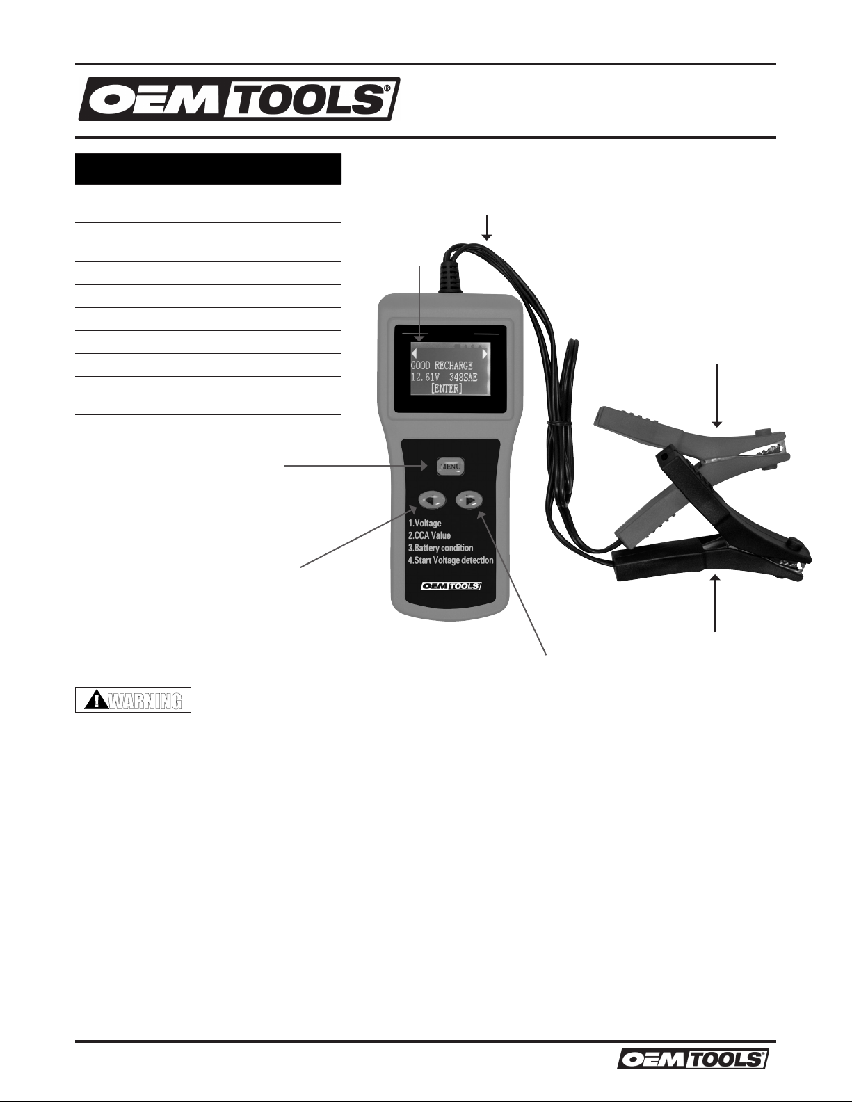
7. Make sure you have put a 9V internal battery into
the tester’s battery chamber. If the LCD screen
shows “POWER LOW”, then the internal 9V battery
needs to be replaced . Replace it before starting
test. Note that nothing will be seen on the screen
until the tester is connected to a vehicle battery.
8. Press the “tu” button to select Battery Test. The
screen will show “BATTERY TYPE” selection.
Press the “t u” button to select the battery type:
REGULAR LIQUID, AGM BATTERY or VRLA/GEL
BATTERY.
9. Press “Enter” button to confirm choice.
10. The screen will show “RATING STANDARD”. Press
the “t u” button to select the battery standard:
SAE、DIN、IEC、EN or CA (MCA)
SAE: United States Standard
EN: European Standard
DIN: German Standard
IEC: International Electrical Science and
Technology Association
CA (MCA): Normal starting current or maritime
starting current
11. Press the “Enter” button to confirm the choice and
go to next step.
12. The screen will show “RATING CAPACITY”. Press
the “t u” button to select the battery capacity of
CCA. With each press of the button, the value will
increase or decrease 5 units.
13. This tester’s testing range:
SAE:、40 ~ 2,000 CCA
EN: 40 ~ 2,100 CCA
DIN:、25 ~ 1,300 CCA
IEC:、30 ~ 1,500 CCA
CA (MCA): 240 ~ 1,440 CA (MCA)
14. Press the “Enter” button to confirm the input value
of the battery capacity and begin the test.
15. The screen will show “TESTING”. Testing is in
progress. The test result will show up after 2
seconds.
16. If the tester asks “BATTERY CHARGED?”, press
the “t u” button to select “YES” or “NO”. Press
“Enter” button to confim choice and proceed to
the next step.
Note: The Tester will judge the battery status and
decide whether to show this Step or not, it doesn’t
appear every time.
05/15
2015 ©OEMTOOLS

6
Operating Instructions and Parts Manual 24369
DIGITAL BATTERY
ANALYZER
17. When the test is completed, the display shows the
actual volts and the actual CCA or %.
18. Press the “t u” button to see the SOH (STATE
OF HEALTH) or SOC (STATE OF CHARGE) as a
percentage.
THE TEST RESULTS ARE AS
FOLLOWING
1. “GOOD PASS” - The battery is good and capable
of holding a charge.
2. “GOOD RECHARGE” - The battery is good but
needs to be recharged.
3. “RECHARGE RETEST” - Battery is discharged, the
battery condition cannot be determined until it is
fully charged. Recharge and retest the battery.
4. “BAD REPLACE” - The battery will not hold a
charge. It should be replaced immediately.
5. “TEST ERROR” - The tested battery is bigger
than 2,000 CCA or the clamps are not connected
properly. Please fully charge the battery and retest
after excluding both previous reasons. If reading
is the same, the battery should be replaced
immediately.
6. Press “ENTER” return to Step 4 to continue
testing or remove the test clamps from the battery
terminal to end test.
STARTING SYSTEM TEST
NOTE: BEFORE BEGINNING THE STARTING AND
CHARGING SYSTEM TEST, MAKE SURE THE
BATTERY IS IN GOOD CONDITION AND FULLY
CHARGED.
1. Connect the tester to a vehicle battery; the tester
will be in default “BATTERY TEST” mode. Press
the “u” button once to enter “SYSTEM TEST”.
The voltage, “XX.XX V” also appears on the
screen. Press the “Enter” button to go to next
step. The screen will show “TURN OFF LOADS
START ENGINE”.
2. Turn off all vehicle accessory loads such as lights,
air conditioning, radio, etc. and then start the
engine. Wait for the tester to detect the cranking
voltage.
3. When the engine is started and test complete, one
of the three results will be displayed along with the
actual reading measured.
a. “CRANKING VOLTS NORMAL”. The system
cranking voltage is in a good range.
b. “CRANKING VOLTS LOW”. The cranking
voltage is below normal limits; troubleshoot
the starter with manufacturer’s recommended
procedure.
c. “CRANKING VOLTS NOT DETECTED”. The
cranking voltage is not detected, retest. Press
the “Enter” button to go to next step.
CHARGING SYSTEM TEST
1. The screen will show “PRESS ENTER FOR
CHARGING TEST”. Press the “Enter” button to
begin charging test. The screen will show “MAKE
SURE ALL LOADS ARE OFF”. This is for testing
alternator idle voltage. Press the “Enter” button to
go to next step. The screen will show results. One
of the three results will be displayed along with the
actual reading measured.
a. “ALT. IDLE VOLTS NORMAL”. The system is
showing normal output from the alternator. No
problem is detected.
b. “ALT. IDLE VOLTS LOW”. The alternator is
not providing sufficient current to the battery.
Check the belts to ensure the alternator
is rotating with engine running. If the belts
are slipping or broken, replace the belts
and retest. Check the connections from the
alternator to the battery. If the connection is
loose or heavily corroded, clean or replace the
cable and retest. If the belts and connections
are in good condition, replace the alternator.
c. “ALT. IDLE VOLTS HIGH”. The voltage output
from the alternator exceeds the normal
limits of a functioning regulator. Check to
ensure there are no loose connections and
the ground connection is normal. If there is
no connection issue, replace the regulator.
Since most alternators have the regulator
built-in, this will require you to replace the
alternator. The normal high limit of a typical
automotive regulator is 14.7 volts +/- 0.05.
Check manufacturer specifications for the
correct limit, as it will vary by vehicle type and
manufacturer.
2. With the engine at idle, press “ENTER” for the
charging system with accessory loads test. Turn
on the blower to high (heat), high beam headlights,
and rear defogger. Do not use cyclical loads such
as air conditioning or windshield wipers.
3. The screen will show “TURN ON LOADS AND
PRESS ENTER”.
05/15
2015 ©OEMTOOLS

7
Operating Instructions and Parts Manual 24369
DIGITAL BATTERY
ANALYZER
4. When testing older model diesel engines, you may
need to run up the engine to 2,500 RPM for 15
seconds.
5. Press the “ENTER” key to test the charging system
with accessory loads. One of the three results
will be displayed along with the actual testing
measured.
a. “ALT. LOAD VOLTS NORMAL”. The system is
showing normal output from the alternator. No
problem detected.
b. “ALT. LOAD VOLTS LOW”. The alternator is
not providing sufficient current for the systems
electrical loads and the charging current for
the battery. Check the belts to ensure the
alternator is rotating with the engine running.
If the belts are slipping or broken, replace
the belts and retest. Check the connections
from the alternator to the battery. If the
connection is loose or heavily corroded, clean
or replace the cable and retest. If the belts and
connections are in good working condition,
replace the alternator.
c. “ALT. LOAD VOLTS HIGH”. The voltage output
from the alternator to the battery exceeds the
normal limits of a functioning regulator. Check
to ensure there are no loose connections
and that the ground connection is normal.
If there are no connection issues, replace
the regulator. Since most alternators have
the regulator built-in, this will require you to
replace the alternator.
6. Press “ENTER” when charging system test is
completed. Turn all accessory loads and engine
off. Press “ENTER” to return to Step 1 or remove
the test clamps from the battery posts after
completion of testing to end test.
7. The screen will show “TEST OVER. TURN OFF
LOADS & ENGINE”.
LANGUAGE SELECT
1. There are five languages you can select: English,
Chinese, German, French and Spanish.
2. Connect the Battery Tester to a vehicle battery.
3. The tester defaults to BATTERY TEST display.
4. Press “u” button twice to get to the LANGUAGE
SELECT display.
5. Press “Enter” button, the display will show all
language options.
6. Press the “u” button to select the language you
want.
7. Press “Enter” button to confirm selection and
return to LANGUAGE SELECT display.
ADJUST DISPLAY BRIGHTNESS
1. Connect the Battery Tester to a vehicle battery.
2. The tester defaults to BATTERY TEST display.
3. Press “u” button three times to get to the LCD
BRIGHTNESS display.
4. Press “Enter” button to show LCD Brightness in
percentage.
5. Press the “u” button to adjust the LCD brightness.
6. Press “Enter” button to save the setting and return
to LCD BRIGHTNESS display.
FAST TEST MODE
1. In fast test mode, the tester will test the vehicle
battery with the parameters saved last time.
Include battery type, battery standard, and battery
capacity.
2. Connect the Battery Tester to a vehicle battery.
3. The tester defaults to BATTERY TEST display.
4. Press “u” button once to get to the FAST TEST
MODE display.
5. Press “Enter” button to test the battery.
6. Tester will show “TESTING”.
7. After about 2 seconds, the test data will be
showed on screen. Includes: battery voltage value
and CCA value.
8. Press “Enter” button to return Step 3.
MAINTENANCE
1. Always store the Battery Tester in a well-protected
area where it will not be exposed to inclement
weather, corrosive vapors, abrasive dust, or any
other harmful elements.
2. Keep the Battery Tester clean for better and safer
performance.
3. Clean clamps and case after each use to prevent
corrosion from battery fluid.
05/15
2015 ©OEMTOOLS

8
Operating Instructions and Parts Manual 24369
DIGITAL BATTERY
ANALYZER
OEMTOOLS™ LIMITED 90 DAY WARRANTY
From 90 days from the original purchase of this product, OEMTOOLS will warranty this item. If you find any
defect in material or workmanship, through normal usage, return it to the place of purchase or to OEMTOOLS
for repair or replacement at our discretion. In order to obtain this service send your tool and proof of purchase,
transportation pre-paid, to OEMTOOLS Q.A. Dept., 3850 Raines Road #3, Memphis. We will not be responsible
for lost or damaged goods during transportation, please insure your package. If our inspection verifies the
defect, we will either repair or replace the product at our election, or we may elect to refund the purchase price if
we cannot readily and quickly provide you with a replacement. We will return repaired products at our expense,
but if we determine there is no defect, or that the defect resulted from causes not within the scope of our
warranty, then you must bear the cost of returning the product.
OEMTOOLS does not provide warranty for products labeled other than OEM or OEMTOOLS. OEMTOOLS will
not provide any warranty for products subjected to abnormal use. Abnormal use includes, but is not limited to,
abuse, accident, alteration, neglect, and unauthorized or unreasonable use or repairs. This warranty does not
cover bits, blades, files, batteries, or calibration. We recommend that you maintain your tools and sharpen or
replace blades, bits, files, and batteries as necessary. OEMTOOLS reserves the right to makes any changes in
construction or design at any time without any obligation in incorporating such changes to tools or equipment
previously sold.
OEMTOOLS makes every effort to assure that its products meet high quality and durability standards, and
warrants to the original purchaser that this product is free from defects in materials and workmanship for the
period of 90 days from the date of purchase. This warranty does not apply to damage due directly or indirectly
to misuse, abuse, negligence or accidents, repairs or alterations outside our facilities, criminal activity, improper
installation, normal wear and tear or to lack of maintenance.
We shall in no event be liable for death, injuries to persons or property, or for incidental, contingent, special or
consequential damages arising from the use of our product. Some states do not allow the exclusion or limitation
of incidental or consequential damages, so the above limitation of exclusion may not apply to you. THIS
WARRANTY IS EXPRESSLY IN LIEU OF ALL OTHER WARRANTIES, EXPRESS OR IMPLIED, INCLUDING THE
WARRANTIES OF MERCHANTABILITY AND FITNESS. This warranty gives you specific legal rights, and you may
also have other rights, which vary from state to state.
05/15
2015 ©OEMTOOLS
Table of contents
Other OEM Tools Measuring Instrument manuals
Popular Measuring Instrument manuals by other brands

niteo
niteo GEDST0363-21 instruction manual

Honeywell
Honeywell BendixKing KLR 10 installation manual

Boumatic
Boumatic TouchPoint OPERATION, SERVICE AND MAINTENANCE INSTRUCTIONS

Novametrix Medical Systems
Novametrix Medical Systems TIDAL WAVE SP 710 user manual

Emerson
Emerson Rosemount X-Stream Series manual

EaseTech
EaseTech ACCURON 7200 Series Installation & operating manual