OEM Tools 24962 User manual

30-inch 4 Drawer Service Cart
CAUTION:
1. Read and follow all safety information and instructions before using this
product for the first time.
2. Fill in the following information and retain the manual for future reference:
Model #: Place of purchase:
Date of purchase: Receipt # of purchase:
PLEASE NOTE: When requesting warranty service please call: 1-866-458-2472
(8:00 a.m. to 5:00 p.m., CST) and have the model number, cash register receipt and the
date of purchase available when you call. DO NOT SHIP YOUR PRODUCT BACK TO THE
STORE, OR TO US, UNLESS WE SEND YOU WRITTEN INSTRUCTIONS FOR RETURN.
CAUTION: TAKE SAFETY PRECAUTIONS WHEN USING YOUR SERVICE CART
LOCK
BRAKE
Do not open more
than one drawer
at a time.
Do not step
or lean on the
drawers.
Do not let
children near
the service cart.
Set the brake on
the locking casters
unless you are moving
the service cart.
Lock drawers
before moving
the service cart.
204JGT005BLK
24962

2
SAFETY
SAFETY
WARNING: READ ALL SAFETY
INSTRUCTIONS BEFORE ASSEMBLING
AND USING THIS PRODUCT.
• WEARSAFETYGLASSESAND
GLOVESwhenassemblingthisproduct.
• DONOTstandonthisproduct.You
may fall, which may cause personal
injury.
• DONOTalterthisproductinany
manner. For example, do not weld
external lock bars or attach electrical
equipment to it. This may cause
product damage or personal injury.
• BECAREFULofsharpedges.
• Keeptheproductonalevelsurface.
The product may become unstable
andtipifstoredormovedonatilted
surface, and may cause personal injury
or product damage.
• Themaximumweightforeachloaded
drawer of the cabinet should be no
more than 100 lb (45 kg).
• ALWAYSWEARANSI-approvedsafety
goggles when working with tools and
equipment.

PARTS LIST
3
FOR SERVICE REGARDING PARTS, ASSEMBLY OR WARRANTY INFORMATION,
PLEASE CALL OUR CUSTOMER SERVICE NUMBER: 1-866-458-2472 (8:00 A.M. TO 5:00 P.M., CST)
LockingCasters(2) Non-Locking
Casters (2)
LockingDrawer
Assembly
ChromeLegs(2)
(with inserts installed)
LongDrawer
Handle (1)
ShortDrawer
Handle (4)
Bottomtray 10mmBolts,
WashersandNuts
(8 pcs. each)
14mmBolts,
WashersandNuts
(8 pcs. each)
Drawer Handle
Screws(12)
Keys(attached to legs) SideWorkBench PryBarHolder
TOOLS REQUIRED FOR ASSEMBLY
• Rubbermallet
•10mmwrench
•Phillipsscrewdriver
• Tableorworkbench
• 2People

ASSEMBLY
4
NOTE: DO NOT FULLY TIGHTEN FASTENERS
UNTIL PROMPTED.
STEP 1:
Assembly preparation
Clear table top and set locking drawer
assembly on table top, with lid facing up.
Position the locking drawer assembly
so that one end hangs off the table
enough to allow the chrome legs to go
through the square holes. Insert one set
ofchromelegsthroughtheoverlapping
holes as shown in Figure 1. Do not bolt
legs to top.
Table or
workbench
Chrome
Legs
Locking Drawer
Assembly
Locking top
STEP 2:
Connect legs and side
accessory to drawer assembly
Choose one of the side accessories (pry
bar holder or side work bench – Figure 2
shows pry bar holder) for attachment to
theoverhangingendoftheservicecart.
Align the outermost bolt holes in the
accessory with the bolt holes in the end
of the cart and with the uppermost holes
in the chrome legs. Position a washer and
insert a 10 mm bolt through the washer,
boltholesandlegsasshown.Secure
bolts with a flat washer, lock washer and
nut on inside of locking drawer assembly.
Tighten bolts until parts fit
together firmly.
REPEAT STEPS 1 AND 2 FOR OTHER END OF
CART, USING REMAINING SIDE ACCESSORY.
Table or
workbench
Chrome
Legs
Locking Drawer
Assembly
Locking top
Pry Bar
Holder
M6 x 40
Bolt
STEP 3:
Connect the bottom
tray to the chrome legs
Liftthecartandplaceontopofthe
bottom tray with chrome legs through
thesquareleg-holes.Alignboltholesin
bottom tray with lower holes in legs and
insert a 10 mm bolt through the washer,
bolt holes and legs as shown. Repeat
with all remaining holes in bottom tray.
Chrome
Legs
M6x40
Bolts
Bottom
Tray

ASSEMBLY
5
STEP 4
IMPORTANT: Tighten all bolts
AT THIS POINT, ALL BOLTS SHOULD BE
TIGHTENED. TIGHTEN BOLTS OPPOSITE
EACH OTHER RATHER THAN TIGHTENING
ALL BOLTS ON ONE SIDE FIRST SO THAT THE
CART REMAINS ALIGNED. AVOID USING
EXCESSIVE FORCE WHEN TIGHTENING
BOLTS. OVER-TIGHTENING BOLTS CAN MAKE
DRAWERS BIND AND HINDER OPERATION.
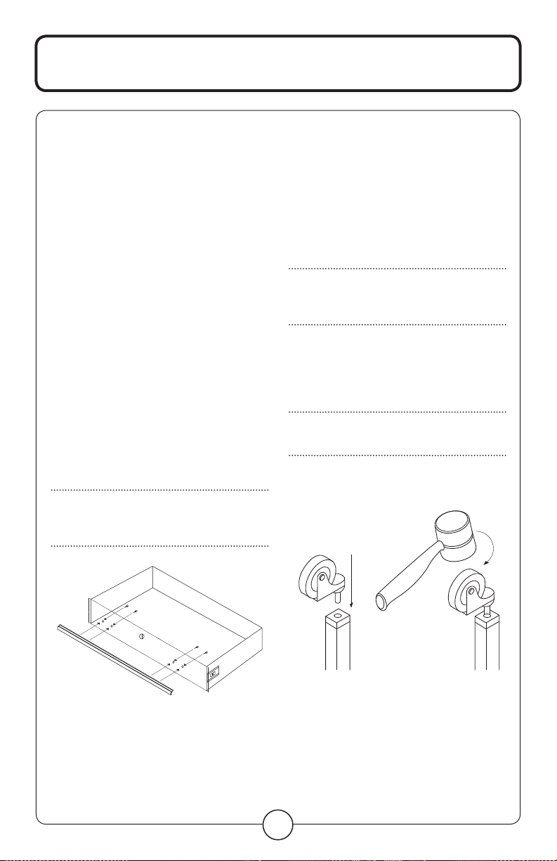
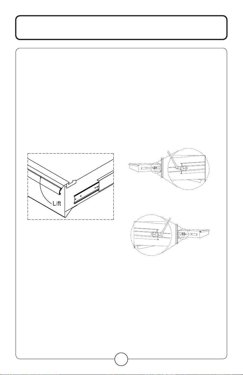
STEP 5
Attach handles to drawer faces
Openthebottomdraweroftheservice
cart. Align the end of the long handle
with the edges of the bottom drawer,
sothatthechannelinthehandlecovers
all four holes in the front of the drawer.
Insert screws through each hole from
inside the drawer and into the drawer
handle channel. Tighten the screws.
Repeat for all remaining drawers using
short handles.
NOTE: DO NOT ALLOW HANDLES TO OVER
HANG THE ENDS OF THE DRAWER
FACES, AS THEY WILL INTERFERE WITH
THE OPERATION OF THE DRAWER.
STEP 6
Attach casters
Withtheprovidedkeys,lockalldrawers,
thetopandtheprybarholdertoprevent
them from opening. Turn the cart upside
down, allowing it to rest on chrome leg
tops with the plastic inserts facing up.
NOTE: DO NOT ALLOW THE SIDE WORK BENCH
TO SWING FREELY, AS IT MAY BE
DAMAGED OR CAUSE INJURY AS CART
IS TURNED UPSIDE DOWN.
Insert the stem of one caster into the hole
in a plastic insert. Using a rubber mallet,
hammer the casters into place until the
stemisnolongervisible.Repeatwith
other casters.
NOTE: MAKE SURE BOTH LOCKING CASTERS
ARE EITHER ON THE RIGHT HAND SIDE
OR LEFT HAND SIDE OF THE CART.
Once all casters are installed, stand the
cart upright. Assembly is complete.

oPERATIon
6
RAISE AND RELEASE
DRAWER FRONTS:
This unit is equipped with the raise and
release drawer fronts. To open, lift up on
the drawer front while pulling towards
you. To close, shut the drawer firmly until
the latch engages. If the drawer does not
stay closed, the hook may be bent, or it
may rub against the drawer slides. To fix
this problem, lightly bend the hook until
the drawer will engage in the slide.
TO REMOVE DRAWERS
Emptydrawer.Pulldrawerouttoalmost
full extension.
Pushuponrighthandblackreleaselever,
while pulling down on the left hand black
releaselever.Whileholdingtheleversin
thepositionsasinstructedabove,pullthe
drawer outward until it is released from
the drawer slide.
PULL DOWN
(LEFT HAND SIDE)
PUSH UP
(RIGHT HAND SIDE)
PULL DOWN
(LEFT HAND SIDE)
PUSH UP
(RIGHT HAND SIDE)
TO REPLACE DRAWERS
Emptydrawer.Extendthedrawerslides
from the tool chest. Insert the brackets on
each side of the drawer into the slots in
the cabinet slides, being careful that they
are properly positioned. Once properly
inserted, completely close the drawer to
set the slides in their proper positions.

REPLAcEMEnT PARTS
7
ITEM PART # REQ’D
QTY
DESCRIPTION
1 * 2 Chrome LeG/ea.
2rssCpLw 2 LoCKinG
CasTer/ea.
3rssCpw 2non-LoCKinG
CasTer/ea.
4rssCpp1 1seT of 4 pL asTiC
inserTs
5rs8013adLxBK 1BoLT KiT (inCL. 8
ea. of 10 mm and
14 mm BoLTs,
nuTs, washers
and 4 sCrews)
68011BK 1pry Bar hoLder
78004BK 1side worK
sTaTion
88002BK 1Top Lid
*Forreplacement,purchaseRSSC7,ChromeLeg,
and8014,LegExtensions.
ALSO AVAILABLE
rs3dhdLB shorT BLaCK dr awer handLe
rs8006hdLB LonG BLaCK drawer handLe
rs8006hdLs handLe sCrews (seT of 4)
rsrBsLideC2 CLip-on roLLer BearinG sLide/pr.
8006CrBBK BL aCK repL aCemenT L arGe drawer
8016BK BL aCK repL aCemenT 3 drawer uniT
8007BK BLaCK repLaCemenT Third sheLf
8013Ls 4-pieCe LoCK & Key se T, Keyed aLiKe
1110 eva foam for Trays/10 pK.
1111 eva foam for drawers/10 pK.
8004ssm ruBBer Liner for side sheLf/10 pK.
FOR SERVICE REGARDING PARTS,
ASSEMBLY OR WARRANTY INFORMATION,
PLEASE CALL OUR CUSTOMER SERVICE
NUMBER: 1-866-458-2472
(8:00 A.M. TO 5:00 P.M., CST)
5
3
7
1
1
6
2
4
8

WARRAnTY
8
WARRANTY
Theservicecartiswarrantedtobe
free from defects in materials and
workmanship for a period of one (1)
year from the date of original purchase.
Ifthisproductisdefective,pleasecall
1-866-458-2472(8:00a.m.to5:00p.m.,
CST).Iftheproductisdefective,wewill
replacethedefectivepartatnocostto
you. Please do not ship your product
back to the store or to us unless we send
you written instructions for return. In
theeventitbecomesnecessaryforyour
product to be returned, we will notify you
how to proceed. A copy of your original
purchase receipt must accompany the
returned product.
WARRANTY CLAIM PROCEDURE
If a claimable defect occurs, please fill
out a claim form through our website
at: www.qualitycraft.com or contact
ourcustomerservicedepartmentat
1-866-458-2472(8:00a.m.to5:00p.m.,
CST).
Beforeyoumakeyourclaimcall,please
makesureyouhave:
1.Thedescriptionoftheservicecart
2. Proof of sale
3. Details regarding the defect
4. Name and address of the owner.
Claims must be filled out in writing
andreturnedwithinsix(6)monthsof
appearance of defect. Failure to comply
with this stipulation will make the
warrantynullandvoid.Wereservethe
righttoathirty-day(30)delayfollowing
receipt of claim in which to inspect the
product.Weassumenoresponsibility
forlaborcostsorremoving/replacing
apreviouslyinstalledproductor
transportation or return of a product.
IMPORTED BY
GreatNeckSaw
1-866-458-2472
Made in China
This manual suits for next models
1
Table of contents
Other OEM Tools Outdoor Cart manuals