OEM AS/T Guide

Bartscher AG
Industrie Fänn Ost
Zugerstrasse 60
CH-6403 Küssnacht am Rigi
Tel.: 041 785 50 00
Fax: 041 785 50 05
www.bartscher.ch
Bedienungsanleitung
Mode d‘emploi
100.953 (AST-400T-000/OM01088)

• Questo apparecchio è conforme alle Direttive
CEE 2006/42-2006/95-2004/108.
•
This applicance complies with the requirements
of Directive
2006/42-2006/95-2004/108
EEC.
• Cet appareil est conforme aux Directives de la
2006/42-2006/95-2004/108 CEE
• Diese Gerät stimmt mit den Bedingungen der
EG - Richtlinie 2006/42-2006/95-2004/108
ARROTONDATRICE
DOUGH ROUNDER
TEIGABRUNDER
BOULEUSE
•
•
AS / T
AS / T
•
•
I
D
F
GB
MANUALE D'USO E LA MANUTENZIONE - PARTI DI RICAMBIO
OPERATING AND SERVICE MANUAL - SPARE PARTS
MODE D'EMPLOI ET D'ENTRETIEN - PIECES DE RECHANGE
GEBRAUCHS- UND INSTANDHALTUNGSHANDBUCH - ERSATZTEILE

2AS / T
INDICE
Index

3
AS / T
AVVERTENZE GENERALI
Leggere attentamente le avvertenze contenute nel presente libretto in quanto forniscono
importanti indicazioni riguardanti la sicurezza di installazione, uso e manutenzione.
Conservare questo libretto per ogni ulteriore consultazione dei vari operatori.
Dopo aver tolto l'imballaggio assicurarsi dell'integrità dell'apparecchiatura. In caso di dubbio,
non utilizzare l'apparecchiatura e rivolgersi a personale professionalmente qualificato. Prima di
collegare l'apparecchiatura, accertarsi che i dati di targa siano corrispondenti a quelli della rete
di alimentazione elettrica: la targhetta dati tecnici è posta sulla fianco destro e riporta tutti i dati
necessari all'installazione.
L'apparecchiaturadeve essereutilizzatasoloda personaleaddestratoall'uso della stessa. Prima
di effettuare operazioni di pulizia e manutenzione, disinserire l'apparecchiatura dalla rete di
alimentazione elettrica. Disattivare l'apparecchio in caso di guasto o di cattivo funzionamento.
Per l'eventuale riparazione rivolgersi solamente ad un centro d assistenza tecnica autorizzato
e richiedere l'utilizzo di ricambi originali.
Il mancato rispetto di quanto sopra può compromettere la sicurezza dell'apparecchiatura.
Tutti i lavori di messa in opera e di installazione possono essere eseguiti esclusivamente da
personale specializzato ed in conformità alle prescrizioni vigenti.
La sicurezza elettrica di questa apparecchiatura é assicurata soltanto quando la stessa é
correttamente collegata ad un efficace impianto di messa a terra come previsto dalle vigenti
norme di sicurezza elettrica. È necessario verificare questo fondamentale requisito di sicurezza,
in caso di dubbio richiedere un controllo accurato dell'impianto da parte di personale
professionalmente qualificato.
Il costruttore non può essere considerato responsabile per eventuali danni causati dalla
mancanza di messa a terra dell'impianto.
L'emissione di rumori dell'apparecchio é inferiore a 85 dB (A).
ISTRUZIONI PER L'INSTALLATORE
1 - POSA IN OPERA DEGLI APPARECCHI
L'APPARECCHIO AS/T PUÒ ESSERE INSTALLATO:
A) Sopra un supporto di sostegno già esistente presso l'utente; in questo caso il piano di
appoggio deve essere in grado di portare il peso della macchina.
Inoltre tenere in considerazione quanto dettato dalle normative ergonomiche.
B) Sopra supporti di portata superiore a 80 kg. che possono essere forniti a richiesta.Togliere
la macchina dall'imballo e sistemare nel luogo di utilizzazione tenendo presente che:
L'apparecchio deve essere messo in opera su un piano perfettamente orizzontale: se
esistono delle aplanarità devono essere eliminate avvitando e svitando i piedini d'appog-
gio regolabili
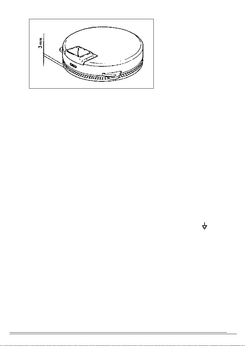
ATTENZIONE: Prima della messa in funzione dell'apparecchio, assicurarsi che la campana sia
posizionata correttamente: il piatto non deve toccare in alcun modo la parte inferiore della
campana (TAV. A) per regolare la distanza vedi cap. 4..."sostituzione campana)

4AS / T
2 - COLLEGAMENTO ELETTRICO
L'apparecchiatura viene consegnata predisposta per il funzionamento alla tensione
riportata nella targhetta caratteristiche.
-L'apparecchiatura viene consegnata predisposta per il funzionamento alla tensione
riportata nella targhetta caratteristiche.
-L'apparecchiatura é dotata di un cavo flessibile per l'allacciamento alla linea elettrica del
tipo con isolamento in gomma H07RN - F e di sezione come da "dati tecnici dell'appa-
recchio".
-L'equipaggiamento elettrico della macchina deve essere connesso a un conduttore
neutro (N). Se alimentato a 400 V.
-Assicurarsi che il voltaggio e la potenza di rete siano adeguati ad erogare i kilowatts
richiesti come da "dati tecnici dell'apparecchio".
Il collegamento alla linea elettrica è possibile solo se tra la rete di alimentazione e la
macchina, esiste un interruttore principale murario onnipolare conforme alle norme
vigenti, con un'apertura di contatto minima di 3 millimetri per polo. Inoltre la tensione
di alimentazione a macchina funzionante , non deve discostarsi dal valore della tensione
nominale di +/- 10%.
L'interruttore principale deve essere situato in prossimità della macchina e deve essere
di facile accessibilità.É indispensabile collegare l'apparecchiatura a terra e verificare
l'efficacia dell'allacciamento elettrico di protezione. L'apparecchiatura deve essere
inoltre inclusa in un sistema equipotenziale la cui efficacia opportunamente verificata
secondo quanto riportato nella normativa in vigore.
Il collegamento viene effettuato mediante una vite contrassegnata dal simbolo , posta
nella parte posteriore dell'apparecchio.
All'accensione della macchina accertarsi che il senso di rotazione del piatto coincida con
la freccia posta sull'arrotondatrice (senso orario).In caso contrario disinserire immedia-
tamente la macchina dalla rete di alimentazione elettrica e invertire le due fasi
direttamente sulla spina del cavo di alimentazione.
IL COSTRUTTORE DECLINA OGNI RESPONSABILITÀ QUALORA QUESTA NORMA AN-
TINFORTUNISTICA NON VENGA RISPETTATA
3 - SISTEMI DI SICUREZZA DELL' APPARECCHIATURA
AS/T é dotata di un fungo d'arresto d'emergenza con interblocco meccanico SB1, da
azionare ogni volta che si presenta una situazione anomala durante la fase di funzionamento
della macchina.Il motore della AS/T é protetto da un relé termico a riarmo automatico, che
si trova all’interno del motore.
TAV. A

5
AS / T
4 - SOSTITUZIONI PARTI DI RICAMBIO
-COMPONENTI ELETTRICHE ARROTONDATRICE:
Tolto il fondo si accede facilmente a tutti i componenti.
-MOTORI
Basta togliere il fondo dell'arrotolatrice e si accede al motore.
-SOSTITUZIONE CAMPANA
Liberare la campana dagli agganci ruotando la stessa in senso antiorario. Dopo aver
rimosso eventuali residui di pasta, inserire la nuova "campana", ruotandola in senso
orario sino all'avvenuto aggancio.
Il piatto non deve toccare in alcun modo la parte inferiore della campana
Per un funzionamento corretto si raccomanda una distanza (luce) di 3 mm. tra piatto e
campana (TAV. A ).
ATTENZIONE: Assicurarsi che tale distanza sia ugualmente presente, per tutti gli agganci (nr.
3) posizionati a 120°C, diversamente non si avrebbe parallelismo tra la superficie fissa
(campana) e quella girevole del (piatto)
Per regolare la "luce" tra piatto e campana, allentare il dado A (autobloccante) fig. 3 )
riposizionare la bussola B la quale determina il corretto posizionamento (verificare con
uno spessore da 3 mm.
Bloccare la bussola con il dado A mantenendola in posizione tramite punteruolo adatto negli
appositi fori.
ISTRUZIONE PER L'UTENTE
Si raccomanda all'utente di verificare che l'installazione dell'apparecchio sia stata fatta in modo
idoneo; la ditta costruttrice non risponde delle garanzie o danni fatti derivanti da cattiva
installazione, imperfetta manutenzione, imperizia d'uso.
Prima di mettere in funzione la AS/T leggere attentamente le istruzioni per l'uso contenute nel
presente libretto, con particolare attenzione alle normative relative ai dispositivi di sicurezza.
Spegnere sempre l'interruttore elettrico principale alla fine dell'utilizzazione dell'apparecchio
, soprattutto durante le operazioni di manutenzione, e riparazione.La macchina deve essere
impiegata solo per lo scopo previsto:
ARROTOLATRICE DI PASTA PER PIZZA.
Essa deve essere utilizzata conformemente alle regole e pulita accuratamente.
Tutti i dispositivi di sicurezza devono essere mantenuti efficienti.
Variazioni ed applicazioni sulla macchina di dispositivi non sono ammesse e comportano la
cessazione in ogni prestazione in garanzia.
5 - USO DELL'APPARECCHIO - FIG 1
Premere il pulsante di marcia.
A macchina in movimento introdurre la porzione di pasta nell'apposito imbuto recuperandola
arrotondata all'uscita, come indicato nella figura 1

6AS / T

7
AS / T
7 - PULIZIA E MANUTENZIONE
Prima di iniziare le operazioni di pulizia e/ o manutenzione scollegare in modo onnipolare
la macchina della rete elettrica. Pulire giornalmente la macchina con acqua tiepida
saponata, quindi risciacquare abbondantemente e asciugare con cura. Evitare nel modo
più assoluto di pulire con pagliette, spazzole o raschietti di acciaio comune in quanto
possono depositare particelle ferrose che ossidandosi provocano punti di ruggine.
Evitare di ricorrere all'uso di lame che provochino danni o rugosità superficiali.
ATTENZIONE: non lavare l'apparecchiatura con getti d'acqua diretti e in pressione poiché
eventuali infiltrazioni ai componenti elettrici potrebbero pregiudicare il regolare
funzionamento della apparecchiatura e dei sistemi di sicurezza.
Non sono necessari particolari lavori di manutenzione, ma si raccomanda di far controllare
l'apparecchio da specialisti ogni 4 anni.Una buona manutenzione garantisce un perfetto
funzionamento ed una lunga durata dell'apparecchio.
POTENZA
Kw
TENSIONE
V - AC
CAVO
(Tipo H07RNF)
380...400/V3N~
230 ~ 3
230 ~ 1
AS / T
0,37
0,37
0,37
5 x 1,5 mm
2
4 x 1,5 mm
2
3 x 1,5 mm
2
ALLACCIAMENTO
ELETTRICO
MOD
DATI TECNICI

8AS / T
GENERAL INSTRUCTIONS
The instructions contained in this handbook shall carefully be read, as they report
important indications regarding the installation, use and maintenance safety..
This handbook shall be kept for any further consultation by the different users.
After removing the packing, check the machine integrity. If there should be any doubts,
do not utilize the machine and contact skilled personnel. Before connecting the machine,
assure that the plate data correspond to the ones belonging to the power supply: the plate
reporting the technical data is placed on the right-hand side and contains all the necessary
data for the installation.
The machine shall only be utilized by skilled personnel. Before carrying out any cleaning
or maintenance procedures, disconnect the machine from the power supply. Disconnect
the machine in case of troubles or malfunction. For possible repairs, only contact a
technical authorized service and ask for original spare parts.
Thenon-compliancewiththeabovementionedinstructionscouldjeopardizethemachine
safety.
All the installation procedures shall only be carried out by skilled personnel and in
compliance with the rules in force.
The electrical safety of this machine is assured, when the machine is correctly connected
with aneffective earthing , as per the electric safety rules in force. It is necessary to verify
this substantial safety requirement, if there are any doubts, require a careful checking of
the machine by skilled personnel.
The manufacturer disclaims all responsibility for possible damages due to a lack of
earthing.
The noise emission of the machine is lower than 85 dB (A).
INSTRUCTIONS FOR THE INSTALLER
1 - INSTALLATION OF THE MACHINES
THE AS/T MACHINE CAN BE INSTALLED AS FOLLOWS:
A) on a support already at the user’s premises; in this case, the face shall be able to
bear the machine weight.
Moreover, you shall consider the ergonomic rules.
B) On supports having a capacity exceeding 80 kgs. Remove the packing and set up
in the utilization place, considering that:
The machine shall be installed on a perfectly horizontal surface: if there are non-
flatnesses, they shall be eliminated screwing and unscrewing the adjustable
supporting feet
WARNING: Before starting the machine, assure that the bell is positioned in a correct
way: the disk shall absolutely not touch the lower part of the bell (TABLE A), for
adjusting the distance see chapter 4... (replacement of the bell)
ENGLISH

9
AS / T
2 - ELECTRICAL CONNECTION
The machine is supplied prepared for a function according to the tension reported
in the features plate.
-The machine is equipped with a flexible cable having a rubber isolation type H07RN
and a section as per “technical data of the machine” for the connection with the
power supply network
-The electric equipment of the machine shall be connected with a neutral wire (N),
in case it is supplied with 380...400 V.
-Assure that the voltage as well as the network capacity are suited to deliver the
kilowatts required by the “technical data of the machine”.
The connection to the power supply network is only possible if between the supply
network and the machine there is an omnipolar wall cut-out switch in compliance
with the rules in force, with a minimum contact opening measuring 3 mm for each
pole. Moreover, the supply tension shall observe the nominal tension value of +/
- 10%, when the machine is running.
The cut-out switch shall be placed near the machine and easy to operate. It is
necessary to connect the machine to a earthing and to verify the effectiveness of
the protection electrical connection. Moreover, the machine shall be included in an
equipotential system, concerning the latter, you shall verify its effectiveness
according to the rules in force.
The connection is carried out through a screw marked with the symbol , placed
on the rear side of the machine.
At the machine starting stage, assure that the disk direction of rotation corresponds
to the arrow placed on the dough rounder (clockwise). Otherwise, immediately
disconnect the machine from the power supply network and directly invert the two
phases on the supply cable plug.
THE MANUFACTURER DISCLAIMS ALL RESPONSIBILITY, IN CASE THIS ACCIDENT
PREVENTION RULE IS NOT OBSERVED
3 - MACHINE SAFETY SYSTEMS
AS/T is equipped with an emergency stopping head button SB
1
, to be
operated when troubles occur during the machine running. The AS/T motor is
protected by an automatic recharging thermic relay, placed inside the motor.
FIGURE. A

10 AS / T
4 - SPARE PARTS REPLACEMENT
-ELECTRICAL COMPONENTS OF THE DOUGH ROUNDER:
The access to all the components is easy, after removing the machine bottom.
-MOTORS
Removing the dough rounder bottom, you can reach the motor.
-REPLACEMENT OF THE BELL
Release the bell, turning it counterclockwise. After removing eventual dough
residual parts, insert the new “bell”, turning it clockwise until its hooking.
The disk shall absolutely not touch the lower part of the bell
Foe a correct functioning, we suggest a distance (clearance) measuring 3 mm
between disk and bell (TABLE A ).
WARNING: Assure that there is always such distance, for all the hookings (n° 3) positioned
at 120°C, otherwise you do not achieve parallelism between the fixed surface (bell)
and the revolving surface (disk)
For adjusting the “clearance” between disk and bell, loosen the nut A (self-locking
nut) fig. 3 ) position the bush B again, which determines a correct positioning (verify
with a 3 mm-thickness gauge.
Lock the bush with the nut A, keeping it in this position through a suitable punch
in the relevant holes.
INSTRUCTIONS FOR THE USER
The installation of the machine shall be carried out in a suitable way, the user shall check
it; the manufacturer disclaims all responsibility for guarantees or damages resulting from
a wrong installation, imperfect maintenance, improper use.
Before starting the AS/T machine, carefully read the instructions contained in this
handbook, taking particular care to the rules regarding the safety devices.
Always switch off the cut-out switch at the end of any machine utilization , especially
during maintenance and repair procedures. The machine shall only be used considering
the aim it has been developed for, that is to say:
PIZZA DOUGH ROUNDER.
The machine shall be utilized in compliance with the rules and it shall also carefully be
cleaned.
All the safety devices shall constantly be effective..
Changes or applications on the machine of devices are not allowed and would determine
the cessation of any guarantee performance.
5 - UTILIZATION OF THE MACHINE - FIG 1
Press the running push-button.
When the machine runs, insert a dough portion in the relevant funnel, taking it
then rounded at the outlet, as per figure 1

11
AS / T

12 AS / T
POWER
Kw
VOLTAGE
V - AC
CABLE
(Tipo H07RNF)
380...400/V3N~
230 ~ 3
230 ~ 1
AS / T
0,37
0,37
0,37
5 x 1,5 mm
2
4 x 1,5 mm
2
3 x 1,5 mm
2
ELECTRIC
CONNECTION
MOD
TECNICAL DATA
7 - CLEANING AND MAINTENANCE
Before starting any cleaning and/or maintenance procedures, disconnect the
machine from the power supply in omnipolar way. The machine shall be cleaned
every day with water and soap, then rinse with a lot of water and carefully dry.
Absolutely avoid to clean using steel wools, brushes or scrapers made of common
steel, as they could leave ferrous particles, which could create rust points. Do not
utilize blades, which could cause damages or surface roughness.
WARNING: do not wash the equipment using direct water jet or water jets under pressure,
because possible penetrations to electrical components could jeopardize the normal
function of the equipment and of the safety systems, as well.
Particular maintenance procedures are not necessary, but we suggest a check of the
machine by skilled personnel every 4 years. A good maintenance assures a perfect
functioning and a long life of the machine.

13
AS / T
ALLGEMEINE ANMERKUNGEN
Die in diesem Handbuch enthaltenen Anmerkungen bez. Installation, Gebrauch und
Instandhaltung sind sorgfältig zu lesen, da sie wichtige Hinweise enthalten.
DiesesHandbuchistunterBerücksichtigungeventuellerzusätzlichenNachschlagendurch
die verschiedenen Benutzer aufzubewahren.
Nach der Entfernung der Verpackung ist die Integrität der Maschine nachzuprüfen. Im
Zweifelsfalle ist die Maschine nicht zu benutzen und Fachpersonal zu kontaktieren. Vor
irgendwelchem Maschinenanschluss sind die Schilddaten zu überprüfen; dieselben sollen
denjenigen des elektrischen Speisenetzes entsprechen: das Schild mit technischen Daten
befindet sich an der rechten Seite und gibt alle zur Installation notwendigen Daten an.
DieMaschinedarfnurvomFachpersonalbenutztwerden. Vor irgendwelchem Reinigungs-
und Pflegeverfahren ist die Maschine vom elektrischen Speisenetz auszuschalten. Bei
Störungen oder schlechter Funktion ist die Maschine auszuschalten Zur eventuellen
Reparatur ausschliesslich ein befugtes technisches Wartungsdienst kontaktieren und die
Benutzung von Originalteilen verlangen.
Die Nichtbeachtung der obigen Anleitungen kann die Sicherheit der Maschine
beeinträchtigen..
Alle Aufstellungs- und Installationsverfahren dürfen ausschliesslich von Fachpersonal und
nach den geltenden Vorschriften durchgeführt werden.
Die elektrischen Sicherheitsumstände dieser Maschine sind vorhanden, wenn dieselbe an
einer angemessenen Erdungsanlage gemäss den E-Sicherheitsnormen, angeschlossen
ist. Es ist notwendig diese wesentliche Sicherheitssituation festzustellen, im Zweifelsfalle
ist die Nachprüfung durch Fachpersonal zu verlangen.
Der Hersteller lehnt irgendwelche Haftung für eventuelle Schäden aus fehlender
Erdungsanlage der Maschine ab.
Die Geräuschausstrahlungen der Maschine unterschreiten 85 dB (A).
ANWEISUNGEN FÜR DEN MONTEUR
1 - AUFSTELLUNG DER MASCHINEN
DIE AS/T-MASCHINE KANN WIE FOLGT AUFGESTELLT WERDEN:
A) Auf eine schon beim Benutzer vorhandene Stütze; ggf. soll die Auflageebene in der
Lage sein das Maschinengewicht zu tragen.
Ausserdem sind die ergonomischen Richtlinien zu beachten.
B) Auf Stützen mit Tragfähigkeit von mehr als 80 Kg., die auf Verlangen geliefert
werden können.Die Verpackung entfernen und in den Verwendungsort aufstellen;
dabei ist folgendes zu beachten:
Die Maschine ist auf eine ganz horizontale Ebene aufzustellen: sollten Unebenheiten
entstehen, sind dieselben durch die Lockerung oder die Spannung der Schrauben
der einstellbaren Auflagefüsse zu beseitigen
DEUTSCH

14 AS / T

15
AS / T
versehen; dieser Schalter ist immer, bei Störungen während des Maschinenbetriebs,
zu betätigen. Der Motor der AS/T-Maschine ist durch ein thermisches Relais mit
automatischer Aufladung, das sich innen der Motor befindet, geschützt.
4 - ERSETZUNG DER ERSATZTEILE
-ELEKTRISCHE KOMPONENTEN DES TEIGABRUNDERS:
Nach der Entfernung der Unterseite sind alle Komponenten leicht zugänglich.
-MOTOREN
Nach der Entfernung des Abrunders ist der Motor zugänglich.
-ERSETZUNG DER GLOCKE
Durch die Drehung der Glocke entgegen dem Uhrzeigersinn wird dieselbe abgehakt.
Nach der Entfernung eventueller Teigrückstände, die neue “Glocke” einsetzen: zu
diesem Zweck ist die Glocke im Uhrzeigersinn bis zu ihrem Ankuppeln zu drehen.
Die Scheibe soll das untere Teil der Glocke in keinem Fall berühren
Zum korrekten Betrieb empfiehlt es sich einen Abstand (Spiel) von 3 mm. zwischen
Scheibe und Glocke (TAB. A ) zu beachten.
ACHTUNG: Solcher Abstand soll immer, bei allen Kupplungen (Nr. 3) mit 120°C-
Positionieren, vorhanden sein, sonst hätte man keine Parallelität zwischen der
festen Oberfläche (Glocke) und der drehbaren Oberfläche (Scheibe)
Zur Einstellung des “Spieles” zwischen Scheibe und Glocke ist die (selbstsperrende)
Mutter Fig. 3) zu lockern, die Büchse B, die das genaue Positionieren bestimmt,
wieder positionieren (durch einen 3 mm-Dickenmesser feststellen).
Durch die Mutter A die Büchse festhalten und durch angemessenen Treiber in den
entsprechenden Löchern die Büchsenstellung halten.
ANLEITUNGEN FÜR DEN BENUTZER
Der Benutzer soll die richtige Installation der Maschine feststellen; der Hersteller lehnt
irgendwelche Haftung im Bezug auf Garantien oder Schäden aus falscher Aufstellung,
nicht einwandfreier Instandhaltung, ungeeignetem Gebrauch, ab.
Vor dem Inbetriebsetzen der AS/T-Maschine sind die in diesem Handbuch enthaltenen
Gebrauchsanweisungen, mit besonderer Sorgfalt bezüglich der Vorschriften über die
Sicherheitsvorrichtungen, sorgfältig zu lesen.
Der elektrische Hauptschalter ist immer, am Ende jeder Benutzung der Maschine und
insbesondere während Pflege- und Reparaturverfahren, auszuschalten. Die Maschine soll
nur zum vorgesehenen Zweck verwendet werden:
ALS PIZZATEIGABRUNDER.
Die Maschine ist nach den Vorschriften zu benutzen und sorgfältig zu reinigen.
Alle Sicherheitsvorrichtungen sollen stets funktionsgerecht sein.
Änderungen und Anbringungen von Vorrichtungen an der Maschine sind nicht zulässig
und lassen irgendwelche Leistungsgarantie entfallen.
5 - BENUTZUNG DER MASCHINE - FIG. 1

16 AS / T

17
AS / T
LEISTUNG
Kw
SPANNUNG
V - AC
CABLE
(Tipo H07RNF)
380...400/V3N~
230 ~ 3
230 ~ 1
AS / T
0,37
0,37
0,37
5 x 1,5 mm
2
4 x 2,5 mm
2
3 x 1,5 mm
2
ELEKTRISCHER ANSCHLUSS
MOD
TECHNISCHE DATEN
3) Nach der Entfernung eventueller Teigrückstände die Glocke einsetzen: zu diesem
Zweck die Glocke im Uhrzeigersinn bis zu ihrem Anhaken drehen;
7 - REINIGUNG UND INSTANDHALTUNG
Vor irgendwelchem Reinigungs- und/oder Pflegeverfahren ist die Maschine vom
elektrischen Netz in allpoliger Weise auszuschalten. Jeden Tag ist die Maschine mit
Seifenwasser zu reinigen, dann mit viel Wasser spülen und sorgfältig trocknen.
Seifenstahlwollen, Bürsten oder Schaber aus handelsüblichem Stahl sind absolut
nicht zu benutzen, da dieselben Eisenpartikeln absetzen könnten und diese könnten
Rost entstehen lassen. Messer sind auch in keinem Fall zu verwenden, da dieselben
Beschädigungen oder oberflächliche Rauheiten verursachen könnten.
ACHTUNG: die Maschine ist nicht mit direkten Wasserstrahlen oder Wasserstrahlen unter
Druckumständen zu waschen, weil eventuelle Eindringen zu den elektrischen
Komponenten die regelmässige Funktion der Maschine sowie der Sicherheitssysteme
beeinträchtigen könnten.
Keine besonderen Pflegeverfahren sind notwendig, aber es empfiehlt sich alle 4 Jahre
die Maschine durch Fachpersonal nachprüfen zu lassen. Eine gute Instandhaltung
gewährleistet einen einwandfreien Betrieb und eine lange Lebensdauer der Maschine.

18 AS / T

19
AS / T
2) CONNECTION ELECTRIQUE
.L’équipement est livré avec prédisposition pour le fonctionnement, à la tension indiquée sur la plaque
des caractéristiques; L’équipement est doté d’un cable flexible pour la connexion au réseau
électrique du type avec insulation en caoutchouc H07RN-F et avec section comme les “données
techniques de l’équipement”.
.Les parties électriques de la machine doivent être connectées avec un conducteur neutre (N) si
alimenté à 380-400V.
.Assurez-vous que le voltage et la puissance soient adéquats pour débiter les Kilowatts demandés
selon les “données techniques de l’appareil”.
La connexion au réseau électrique est possible seulement si, entre le réseau et la machine, il existe
un interrupteur principal mural omnipolaire en conformité avec les normes en vigueur avec une
ouverture de contact min. de 3 mm. par pôle.En outre la tension d’alimentation, quand la machine
est en fonction, ne doit pas
être différente à la valeur de tension nominale de + / - 10 %.
L’interrupteur principal doit être situé près de la machine et il doit être facilement accessible.
Il est indispensable de connecter l’équipement à la terre et vérifier l’efficacité de la connexion
électrique de protection.
En outre l’équipement doit être inclus dans un système équipotentiel dont l’efficacité doit être
opportunement vérifiée selon les données des normes en vigueur.
La connexion est effectuée par deux vis marquées par le symbole placées sur le côté droit près
de l’entrée du cable électrique et l’autre dans le côté postérieur du convoyeur.
Au démarrage de la machine assurez-vous que le sens de rotation de la spirale et du couteau
se vérifie comme indiqué par les flèches placées sur la portionneuse (en sens inverse de celui
des aiguilles d’une montre), tandis que
le sens de rotation du convoyeur doit coincider avec la
flèche placée sur le convoyeur
Au cas contraire débranchez immédiatement la machine du réseau d’alimentation
électrique et inversez les deux phases directement sur la fiche du cable d’alimentation.
REPLACEMENT DES PIECES DE RECHANGE
COMPOSANTES ÉLECTRIQUE BOULEUSE
Après avoir enlevé le fond on accède à toutes les composantes.
MOTEUR
EN LEVANT LE FOND DE LA BOULEUSE ON PEUT ACCÉDER AU MOTOR
REPLACEMENT DE LA CLOCHE
Séparér la cloche des spéciaux crochets en la tournant dans le sens des aguilles d'un montre jusqu'a
l'accrochage; le plat ne doit absolument pas toucher la côuté inférieur de la cloche Pour un correct
foncionnement on recommande un distance de 3 mm. entre le plat et la cloche.
Assurez - vous que cette distance, soit de toute façon présente, pour tous les crochets placés à 120°,
au contraire il n'y aurait pas de parallelisme entr la surface fixe (cloche) et celle tournante (plat)
Pour régler la distance entre plat et cloche, d'ésserrez l'écrou A (autobloquant) positionnez la douille B
qui determine le correct positionnement (vérifier avec l'épaisseur de 3 mm) Bloquez la douille par l'écrou
A en la tenant en position par moyen d'un adéquat pointeau inséré dans les troux spéciaux;
INSTRUCTIONS POUR L’USAGER.
On recommande à l’usager de vérifier que l’installation de l’équipement soit effectuée de façon
adéquate; le constructeur décline toute résponsabilité concernant les garanties ou les dommages
dérivés d’une mauvaise installation, d’un incorrect entretien ou d’une mauvaise utilisation
Avant de démarrer la AS/TABLE lisez attentivement les instructions de service contenues dans ce livret
en prêtant attention aux normes concernant les dispositifs de sécurité.
Eteindre toujours l’interrupteur électrique principal à la fin de l’utilisation de l’équipement, surtout
pendant les opérations d’entretien et de réparation.
Table of contents
Languages:
Other OEM Commercial Food Equipment manuals
Popular Commercial Food Equipment manuals by other brands

BETTCHER INDUSTRIES
BETTCHER INDUSTRIES AirShirz Operating instructions and spare parts list

Atlas Metal
Atlas Metal WB SERIES manual

BURGER KING
BURGER KING Taylor C606 Equipment operation guide

Tefcold
Tefcold LCT750-900 user manual

Convotherm
Convotherm Mini Combi with Easy Touch Service and parts manual

Lotus
Lotus PC-554G Installation and operating instructions

Delfield
Delfield F14EI232 Original instructions

Electrolux Professional
Electrolux Professional IC43316 Operating handbook

Inomak
Inomak MAV67 operating instructions

Cuppone
Cuppone Michelangelo ML 435/1 User and installation manual

GESAME
GESAME MH Super 114 instruction manual

COOL Spot
COOL Spot Cool-Spot user manual