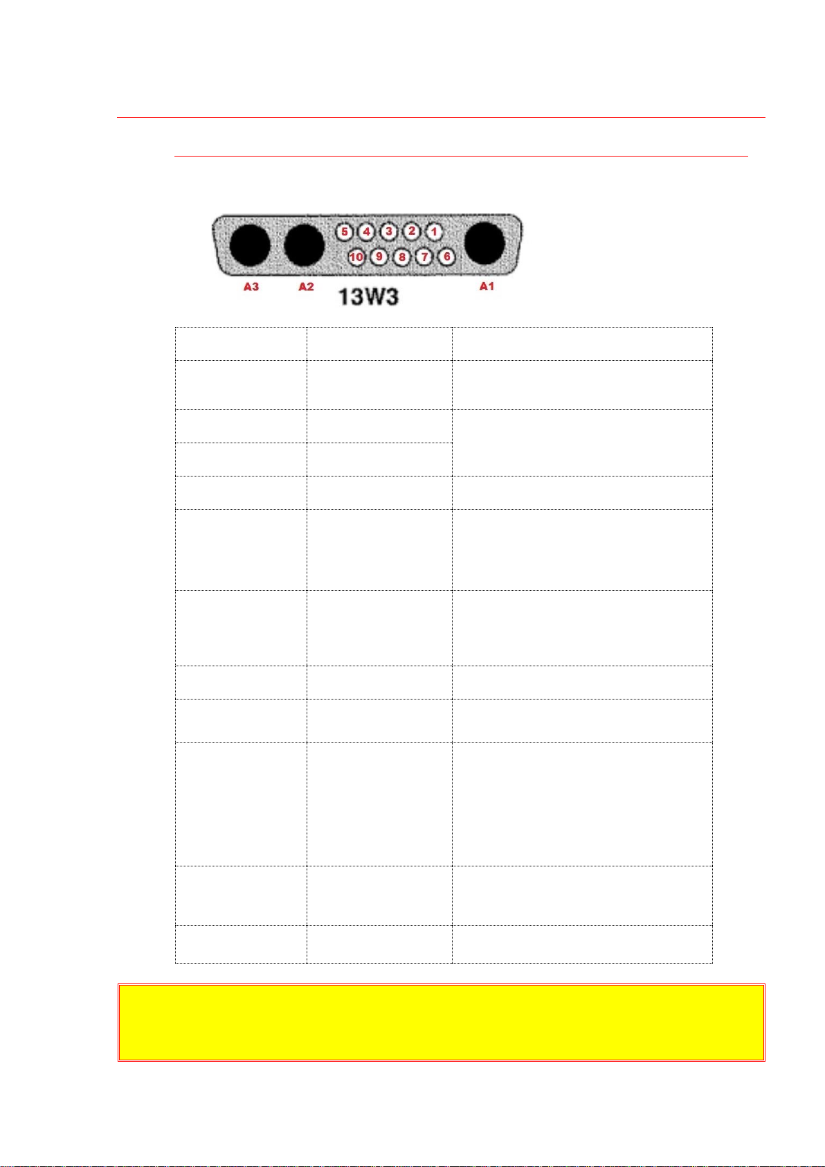
Connectors, pins, interface signals
INTERFACE: 13 pin mixed D-SUB connector of 13W3 type
24V DC (48V DC) power and all the control signals are to be connected here.
Module can be protectively grounded via
this pin
DC power supply should be connected here
DC voltage applied between pins 3 and 4
sets up the output high voltage level
Calibration is linear, 10V between pins 3
and 4 corresponds to VMAX at the output
Return of HV Program signal
In order to improve high voltage stability
HV Program Return isn’t connected to the
common ground of Interface
5V TTL if fault occurred, 0V elsewise.
Fault state is set in the case of overheating.
Pin 7 should be pulled to the ground to
enable the output. Output is disabled while
TTL high level is applied to pin 7 or pin 7 is
left unconnected
To use power supply in stand-alone regime,
pin 7 can be short-circuited with one of
Interface return pins (e.g. pin 10)
Output voltage monitor
Calibration is linear, 10V on pin 8
corresponds to VMAX at the output
Return of all Interface signals (Enable, HV
Monitor, Fault) except HV Program
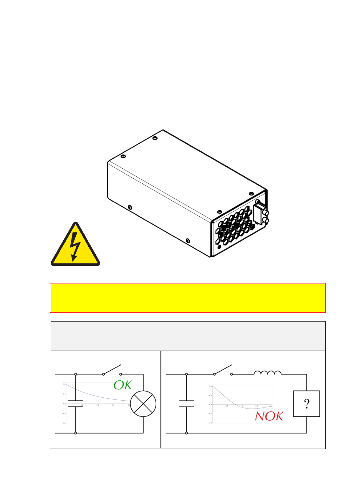
Warning! Because of safety reasons we highly recommend to use low voltage
power supply with DC output galvanically insulated from AC input (insulation strength
4000VAC, 2500VAC or 1500VAC is selected in dependence on your application).