Oerlikon Fairfield Torque-Hub S40B Series User manual

1
Torque-Hub®Planetary Final Drive
S40B Series Service Manual
Rev 09/03/13

2
While every precaution has been taken in the preparation of this document, Fairfield Manufacturing Co. Inc. assumes no
liability with respect to the use of the documentation described herein, or for any act or omission of Fairfield Manufacturing
Co. Inc. concerning this documentation. Torque-Hub®is a registered trademark of Fairfield Manufacturing Co. Inc.
Features and specifications are subject to change without notice.

3
Planetary Final Drive Service Manual
Content
Introduction 4
Roll and Leak Test 5
Tightening and Torquing Bolts 7
Lubrication Information 8
Disassembly Instructions Main Disassembly 12
Cover Disassembly 14
Housing-Spindle Disassembly 15
Output Carrier Disassembly 18
Input Carrier Disassembly 19
Assembly Instructions Cover Subassembly 21
Input Carrier Subassembly 22
Output Carrier Subassembly 24
Housing-Spindle Subassembly 26
Main Assembly 30
Assembly Drawing 32
Parts List 33
Assembly Tools 35
General Information Contact Information 47

4
Planetary Final Drive Service Manual
Introduction
This manual is a step-by-step guide to the disassembly and
assembly of the S40B SeriesTorque-Hub®units with ratios of XX:X
or lower. It is designed for the customer or mechanic who is
repairing this particular Torque-Hub® model.
Users of this manual should note that each part mentioned is
followed by an identification number enclosed in parentheses.
These part numbers may be referred to in the Parts List and
Assembly Drawing sections of this manual.
Specialized tools used to assemble this unit are noted in the
assembly procedures and diagrammed in the Assembly Tools
section.
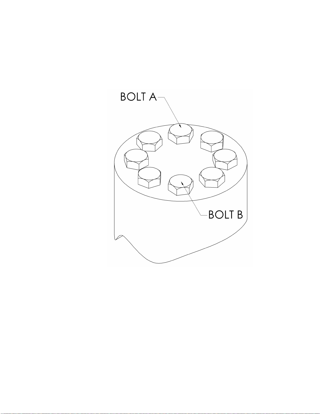
Users should familiarize themselves with the procedures for roll and
leak testing, as well as bolt tightening and torquing found on the
following three pages before starting any repairs.
Standard safety practices should be followed during the
disassembly and assembly procedures described. Safety glasses
and safety shoes should be worn, and heavy, heat resistant gloves
should be used when handling heated components. Be especially
alert when you see the word CAUTION. This indicates that a
particular operation could cause personal injury if not performed
properly or if certain safety procedures are not followed. The word
NOTE is used to bring attention to certain procedures or helpful
hints that will aid in the disassembly and assembly process.

5
Planetary Final Drive Service Manual
Roll and Leak Test
Torque-Hub®units should always be roll and leak tested before
disassembly (if possible) and after assembly to make sure the unit’s
gears, bearings and seals are working properly. The following
information briefly outlines what to look for when performing these
tests.
The Roll Test The purpose of the roll test is to determine if the unit’s gears are
rotating consistently, easily and properly. It should be able to rotate
the gears in the unit applying constant force to the roll checker. If
more drag is felt in the gears only at certain points, then the gears
are not rolling consistently and easily and should be examined for
improper installation or defects. Some gear packages roll with more
difficulty than others. Do not be concerned if the gears in the unit
seem to roll hard as long as they roll with consistency. Rotate the
gearbox both clockwise and counterclockwise the same number of
turns as the ratio of the unit. The gearbox ratio is the same number
as the last three numbers on the ID tag.
Model Code
Roll Test Tool
S40B105525ZY
T224477
Continued on Next Page

6
The Leak Test The purpose of a leak test is to make sure the unit is airtight.
To perform a leak test, use the leak test fixture from the table on
page 10. If the tool is not available, the gearbox must be sealed to
perform the test. This can be accomplished by assembling the
sealed input device onto the gearbox at the input end and replace
one of the oil plugs with an air chuck. DO NOT EXCEED 10 PSI
PRESSURE DURING THE LEAK TEST. Higher pressure will create
a false sealing effect in assemblies with lip-seals. The unit has a
leak if the pressure gauge reading on your leak check fitting starts
to fall after the gearbox has been pressurized and allowed to
equalize. Leaks will most likely occur at the pipe plugs, the main
seal or wherever o-rings or gaskets are located. The exact location
of a leak can usually be detected by brushing a soap and water
solution around the main seal and where the o-rings or gaskets
meet on the exterior of the unit and then checking for air bubbles. If
a leak is detected in a seal, o-ring or gasket, the part must be
replaced and the unit rechecked. Leak test at 10 psi for 20 minutes.
Model Code
Leak Test Tool
S40B105525ZY
T173814

7
Planetary Final Drive Service Manual
Tightening and Torquing Bolts
If an air impact wrench is used to tighten bolts, extreme care should
be taken to ensure the bolts are not tightened beyond their specified
torque. The following steps describe how to tighten and torque bolts
or socket head cap screws in a bolt circle.
1. Tighten (but do not torque) bolt “A” until snug.
2. Go to the opposite side of the bolt circle and tighten bolt “B” until
equally snug.
3. Crisscross around the bolt circle and tighten the remaining bolts.
4. Use a torque wrench to apply the specified torque to bolt “A.”
5. Using the same sequence, crisscross around the bolt circle and
apply an equal torque to the remaining bolts.

8
Planetary Final Drive Service Manual
Lubrication Information
General Properties The lubricant used in most Torque-Hub®drives should be
petroleum-based gear fluid containing anti-oxidation, anti-foaming
and extreme pressure additives. The lubricant should have a
minimum viscosity index of 95 cst and maintain a minimum viscosity
of 40 cst under normal operating conditions. Some applications
require special considerations; consult the machine manufacturer
and Oerlikon Fairfield for more additional information.
The table below lists the recommended viscosities for various
ambient operating temperatures. These recommendations are
based on temperature rise of 50° to 100°F at normal operating
conditions.
Continued on Next Page
Differential Planetary Simple Planetary
Ambient
Temperature
ISO Index
AGMA
Lubricant
Number
ISO Index
AGMA
Lubricant
Number
-40° to -5° F(1)
VG100
3EP
VG100
3EP
-5°to 40° F
VG150
4EP
VG100
3EP
40° to105° F
VG220/VG320
5EP/6EP
VG150/VG220
4EP/5EP
105° to 150° F(2)
VG460
7EP
VG320
6EP
Footnotes
1. For operation in this ambient temperature range, synthetic oil is recommended with a pour point of
10°F lower than the minimum ambient temperature.
2. For operation in this ambient temperature range, synthetic oil is recommended for proper lubricant
life at elevated temperatures.

9
Maintenance Oil amounts for each series of Torque-Hub®drives are indicated in
the appropriate series literature. An initial oil change should be
made after the first 50 hours of operation. Subsequent oil changes
should be made at 1,000 hour intervals or annually, whichever
comes first.
Oil temperatures should be not higher than 160° to 180°F for
continuous operation, and no higher than 200°F for intermittent
operation. For special applications, high horsepower, high speeds
or wide temperature changes, please consult Oerlikon Fairfield.
Oil Fill Level When the Torque-Hub®unit is mounted horizontally, unless
otherwise specified, the gearbox should be filled half-full of oil.
Consult the appropriate series literature for approximate fill
volumes. Vertically mounted Torque-Hub®units may require special
lubrication procedures. Please contact Oerlikon Fairfield for
vertically mounted applications.

10
DISASSEMBLY

11
THIS PAGE
INTENTIONALLY
LEFT BLANK

12
Planetary Final Drive Service Manual
Main Disassembly
1. Perform a roll check and a leak check prior to disassembling the unit.
2. Remove two magnetic Pipe Plugs (14) and drain oil out of gearbox.
NOTE: Record the condition and volume of the oil.
3. Remove Bolts (12) from the Cover Subassembly.
4. Lift the Cover Subassembly off of the unit.
Continued on Next Page

13
5. Remove the Input Sun Gear (6).
6. Remove Input Carrier Subassembly out of the unit.
7. Remove Flanged Bolts (11) from Ring Gear thru Hun Spindle subassembly.
8. Remove the Ring gear (18) off of the Hub-Spindle Subassembly.
9. CAUTION: Safety glasses must be worn during these next steps.
8. Remove Sun Gear (7) from Output Carrier Subassembly.
9. Remove External Retaining Ring (26) from the groove on Sun Gear (7).
10. Remove Bolts (28) and remove the Locking Plate (27) from Internal Coupling (1H).
11. Lift out the Output Carrier Subassembly from Hub-Spindle Subassembly.
This concludes the Main Disassembly.

14
Planetary Final Drive Service Manual
Cover Disassembly
1. Remove the O-Ring (8) from groove in the Cover Plate (5) and discard it.
2. Remove Thrust Washer (9) from the Thrust Bearing (10).
3. Remove Thrust Bearing (10) from the Thrust Washer (9).
4. Remove Thrust Washer (9) from the groove on the Cover Plate (5).
5. Remove Thrust Washer (17) from the Cover Plate (5).
This concludes the Cover Disassembly.

15
Planetary Final Drive Service Manual
Housing-Spindle Disassembly
1. Set the unit on a bench so that the Spindle (1A) flange is down.
Continued on Next Page

16
2. Remove O-Ring (25) from the Housing (1G) and discard it.
3. Remove Hexagonal Bolts (1J) from Spindle (1A).
4. Remove Bearing Carrier (1P) from the Spindle (1A).
CAUTION: The Shim edges are sharp; wear gloves when handling or installing Shims to
prevent injury.
5. Remove Steel Shims (1I) from the Internal Coupling (1H).
6. Remove Internal Coupling (1H) from the Hub (1G).
7. Remove Bearing Cone (1F) from spline end of the Internal Coupling (1H).
8. Turn over the unit and carefully place the unit on a support base until the Spindle (1A) rests
on it. Ensure there is enough gap to lower the Housing (1G) down.
9. Using a dead blow hammer on the Housing (1G) flange to drive the Hosing (1G) off of the
Spindle (1A).
10. Lift the Spindle (1A) out of the Housing (1G).
11. Remove the Boot Seal (1U) from the Housing (1G).
Continued on Next Page

17
12. Remove the Face Seal (1B) from the Housing (1G) and Spindle (1A).
13. Remove outboard Bearing Cone (1D) from the Housing (1G).
14. Using a hammer and punch drive the inboard Bearing Cup (1E) out of the Housing (1G). Be
careful not to damage the counter bore in the housing.
15. Turn the Housing (1G) over and drive the outboard Bearing Cup (1C) out of the Housing. Be
careful not to damage the counter-bore in the housing.
16. Remove Pipe Plug (1V) from the Spindle (1A).
17. Remove Pipe Plug (1T) from the Housing (1G).
18. Remove Pipe Plug (1K) from the Housing (1G).
This concludes the Housing-Spindle Disassembly.

18
Planetary Final Drive Service Manual
Output Carrier Disassembly
1. Unbend the tang of Lock-Tanged Washer (2I) from the Bearing Nut (2H) and remove the
Bearing Nut (2H) from the Planet Shaft (4K).
2. Remove Lock-Tanged Washer (2I) from the Planet Shaft (4K).
3. Remove Lock Pin (2J) from the slot of the Carrier (4A) and Planet Shaft (4K).
4. Remove the Planet Shaft (4K).
5. Slide out the Planet Gear Subassembly from the window of the Carrier (4A).
6. Remove Thrust Washer (2F) from the window of the Carrier (4A).
7. Remove Bearing Cones (4D) from the bore of the Planet Gear (4B).
8. Remove Bearing Cups (4C) from the bore of the Planet Gear (4B).
9. Remove Thrust Spacer (4F) from the bore of the Planet Gear (4B).
CAUTION: Safety glasses must be worn during these next steps.
10. Remove Retaining Ring (4E) from internal groove of the Planet Gear (4B).
11. Repeat the steps 1 through 9 for the remaining two Planet Gears (4B).
This concludes the Output Carrier Disassembly.

19
Planetary Final Drive Service Manual
Input Carrier Disassembly
1. Unbend the tang of Lock-Tanged Washer (2I) from the Bearing Nut (2H) and remove the
Bearing Nut (2H) from the Planet Shaft (2K).
2. Remove Lock-Tanged Washer (2I).from the Planet Shaft (2K).
3. Remove Lock Pin (2J) from slot of the Carrier (3A) and Planet Shaft (2K).
4. Remove the Planet Shaft (2K).
5. Slide out Planet Gear Subassembly from the window of Carrier (2A).
6. Remove Thrust Washer (2F) from the window of the Carrier (2A).
7. Remove Bearing Cones (2D) from the bore of the Planet Gear (2B).
8. Remove Bearing Cups (2C) from the bore of the Planet Gear (2B).
9. Remove Thrust Washer (2E) from the bore of the Planet Gear (2B).
CAUTION: Safety glasses must be worn during these next steps.
10. Remove Retaining Ring (2G) from the internal groove of the Planet Gear (2B).
11. Repeat steps 1 through 9 for the remaining two Planet Gears (2B).
This concludes the Input Carrier Disassembly.

20
ASSEMBLY
Table of contents
Other Oerlikon DC Drive manuals
Popular DC Drive manuals by other brands

Bucher
Bucher EMD G 0 Series Hardware manual

Rockwell Automation
Rockwell Automation Allen Bradley Kinetix 7000 2099-BM06-S Design guide

Eaton
Eaton DX-NET-PROFINET-2 manual

Nidec
Nidec Answer Drives 700E Installation & operating instructions

Sprint Electric
Sprint Electric 400i product manual

GFA
GFA 10003166 10011 installation instructions