OFFCAR UNICO Series Manual

1
IT –EN –FR –DE –ES
LEGGERE LE ISTRUZIONI PRIMA DI UTILIZZARE L’APPARECCHIO
READ INSTRUCTIONS BEFORE USING THE APPLIANCE
LIRE LES INSTRUCTIONS AVANT D'UTILISER L'APPAREIL
LESEBEFEHLE VOR INBETRIEBNAHME DER GERÄTE
LEA LAS INSTRUCCIONES ANTES DE USAR EL APARATO
FRY-TOP A GAS 700 UNICO E 6 UNICO
LIBRETTO DI ISTRUZIONI, USO E MANUTENZIONE
Cod. 888670
Rev.00
05/2012
SOMMARIO
1.
AVVERTENZE GENERALI
Pag. 1
2.
INSTALLAZIONE
Pag. 2
2.1
Pag. 2
2.2
Posa in opera degli apparecchi
Pag. 2
2.3
Scarico fumi
Pag. 2
2.4
Collegamento gas
Pag. 3
3.
CARATTERISTICHE TECNICHE
Pag. 3
Tabella 1 (consumi gas)
Pag. 3
Tabella 2 (dati tecnici bruciatori SERIE STILE UNICO)
Pag. 3
Tabella 3 (dati tecnici bruciatori SERIE 6 UNICO)
Pag. 3
Tabella 4 (fry-top SERIE STILE UNICO e 6 UNICO)
Pag. 3
4.
FUNZIONAMENTO CON GAS D’ALIMENTAZIONE IDENTICO A QUELLO PREDISPOSTO
Pag. 4
4.1
Controllo della pressione di alimentazione
Pag. 4
5.
REGOLAZIONE PER FUNZIONAMENTO CON ALTRI TIPI DI GAS
Pag. 4
5.1
Pag. 4
5.2
Pag. 4
5.3
Regolazione dei minimi
Pag. 4
5.4
Pag. 4
5.5
Regolazione dei minimi
Pag. 4
6.
ISTRUZIONI D’USO
Pag. 5
6.1
Accensione della fiamma pilota SERIE STILE UNICO
Pag. 5
6.2
Accensione del bruciatore principale
Pag. 5
6.3
Spegnimento
Pag. 5
6.4
Accensione del bruciatore principale SERIE 6 UNICO
Pag. 5
6.5
Spegnimento
Pag. 5
7.
MANUTENZIONE
Pag. 5
1. AVVERTENZE GENERALI
Leggere attentamente le avvertenze contenute nel presente libretto in quanto forniscono importanti indicazioni riguardanti
e. Conservare questo libretto per ogni ulteriore consultazione futura.
o.
e gas.
Prima di effettuare operazion
un centro di assistenza tecnica autorizz
L’allacciamento, la posa in opera dell’impianto e degli apparecchi, la ventilazione, lo scarico fumi devono essere effettuati
secondo le istruzioni del costruttore, da personale professionalmente specializzato, conformemente alle norme vigenti.

2
Vanno inoltre rispettate le disposizioni antincendio vigenti, i regolamenti edilizi e disposizioni antincendio locali, le norme
antinfortunistiche vigenti e le disposizioni dell’ente di erogazione del gas.
Non ostruire le aperture o fessure di aspirazione o di smaltimento del calore.
Onde evitare rischi di ossidazione o di aggressioni chimiche in genere, occorre tenere ben pulite le superfici in acciaio
inossidabile.
Pulire giornalmente le parti in acciaio inox con acqua tiepida saponata, quindi risciacquare abbondantemente ed
asciugare con cura.
possono depositare particelle ferrose che ossidandosi provocano punti di ruggine. Può essere eventualmente adoperata
lana di acciaio inossidabile nel senso di satinatura.
tutte le superfici in acciaio un panno imbevuto di olio di vaselina in modo da stendere un velo protettivo; inoltre arieggiare
periodicamente i locali.
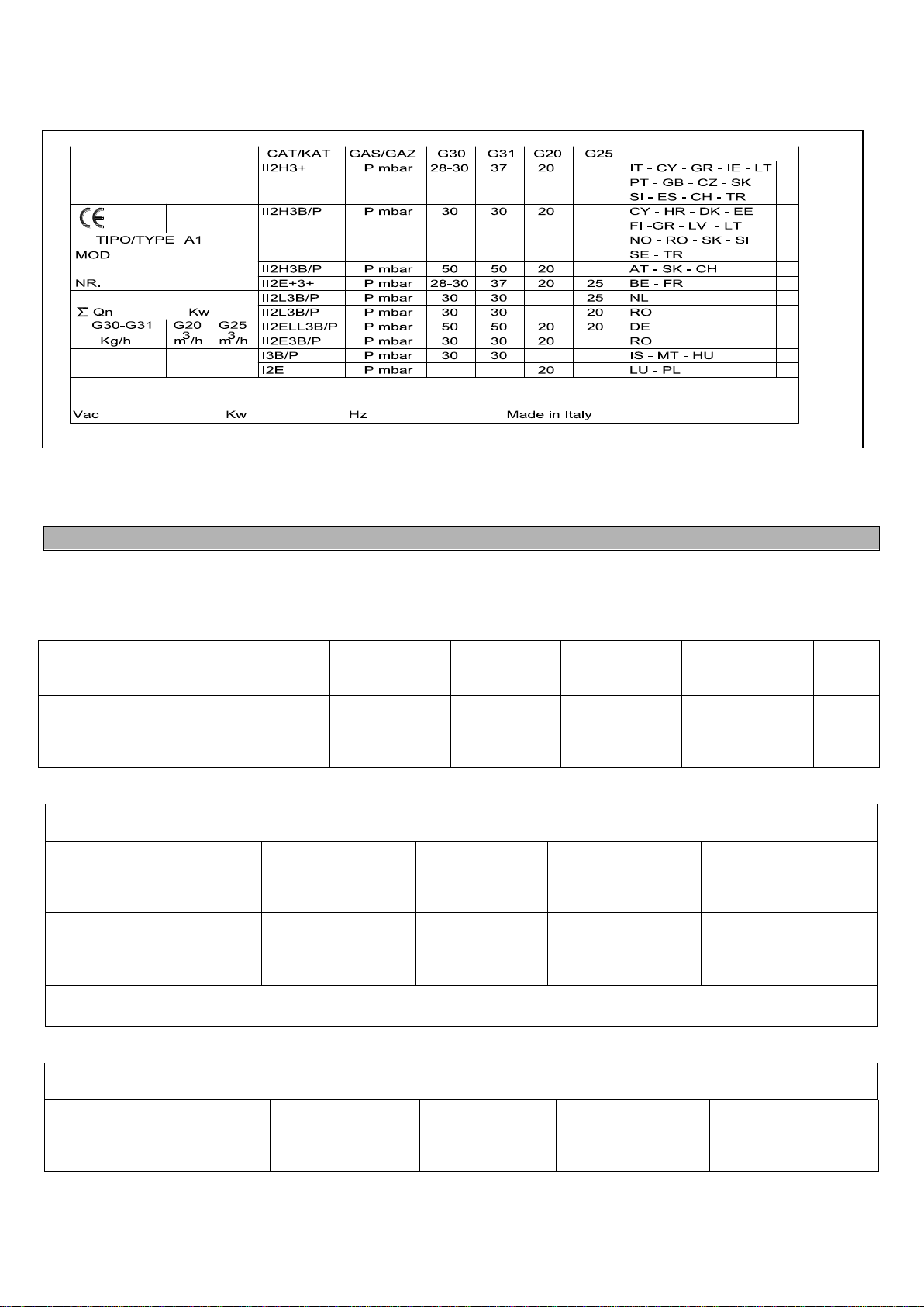
Prima di procedere al collegamento controllare sulla targhetta tecnica che l’apparecchio sia stato collaudato ed
omologato per il tipo di gas a disposizione presso l’utente.
Nel caso che il tipo di gas indicato sulla targhetta non sia quello di cui si dispone, seguire le indicazioni nel paragrafo
La casa costruttrice declina ogni responsabilità per le possibili inesattezze contenute nel presente opuscolo imputabili ad
errori di trascrizione o stampa. Si riserva inoltre il diritto di apportare al prodotto quelle modifiche che ritiene utili o
necessarie, senza pregiudicarne le caratteristiche essenziali.
La ditta costruttrice declina ogni e qualsiasi responsabilità qualora non venissero strettamente osservate le norme
contenute in questo manuale.
i da errata installazione, manomissione
LO SMALTIMENTO DELLA MACCHINA, AL TERMINE DEL CICLO DI LAVORO, DEVE ESSERE EFFETTUATA IN
CONFORMITÀ ALLE NORMATIVE VIGENTI. LA MACCHINA DEVE ESSERE CONSEGNATA A PERSONALE
AUTORIZZATO PER IL RECUPERO E LO SMALTIMENTO DI PARTI DELLA STESSA.
2. INSTALLAZIONE
2.1 Installazione dell’apparecchio
inconvenienti agli impianti, deve essere eseguita unicamente da personale qualificato, nel rispetto delle norme in vigore.
Gli impianti a gas, ed i locali di installazione degli apparecchi devono rispondere
alle regolamentazioni esistenti nelle varie zone ed in particolare si deve
ri a 2 m3/h
per ogni kW di potenza installata e che devono essere osservate le Norme
prevenzione infortuni.
2.2 Posa in opera degli apparecchi
provvedendo alla loro messa a bolla e regolazione in altezza mediante i piedini
regolabili o altri mezzi.
Togliere dai pannelli esterni la pellicola protettiva, staccandola lentamente per
impedire che rimanga il collante.
È contro il calore.
Interporre fogli refrattari oppure piazzare gli apparecchi da almeno 200 mm di
distanza dalle pareti laterali o posteriori.
2.3 Scarico fumi
Gli apparecchi devono essere installati in locali adatti per lo scarico dei prodotti della combustione che deve avvenire nel
rispetto di quanto prescritto dalle norme di installazione. Le nostre apparecchiature sono considerate (vedi tabella 1 dati
tecnici) come: APPARECCHI A GAS DI TIPO “A1”
Gli apparecchi di tipo A1 devono essere installati in locali sufficientemente ventilati per prevenire la concentrazione di
Gli apparecchi di tipo A1 non necessitano del collegamento diretto ad un condotto di scarico dei prodotti di combustione.
I prodotti della combustione però devono essere convogliati in apposite cappe o dispositivi similari, collegate ad un
direttamente in ambiente esterno, di portata non
le norme in vigore, indicativamente per un totale di 35 m³/h per ogni kW di potenza gas installata.
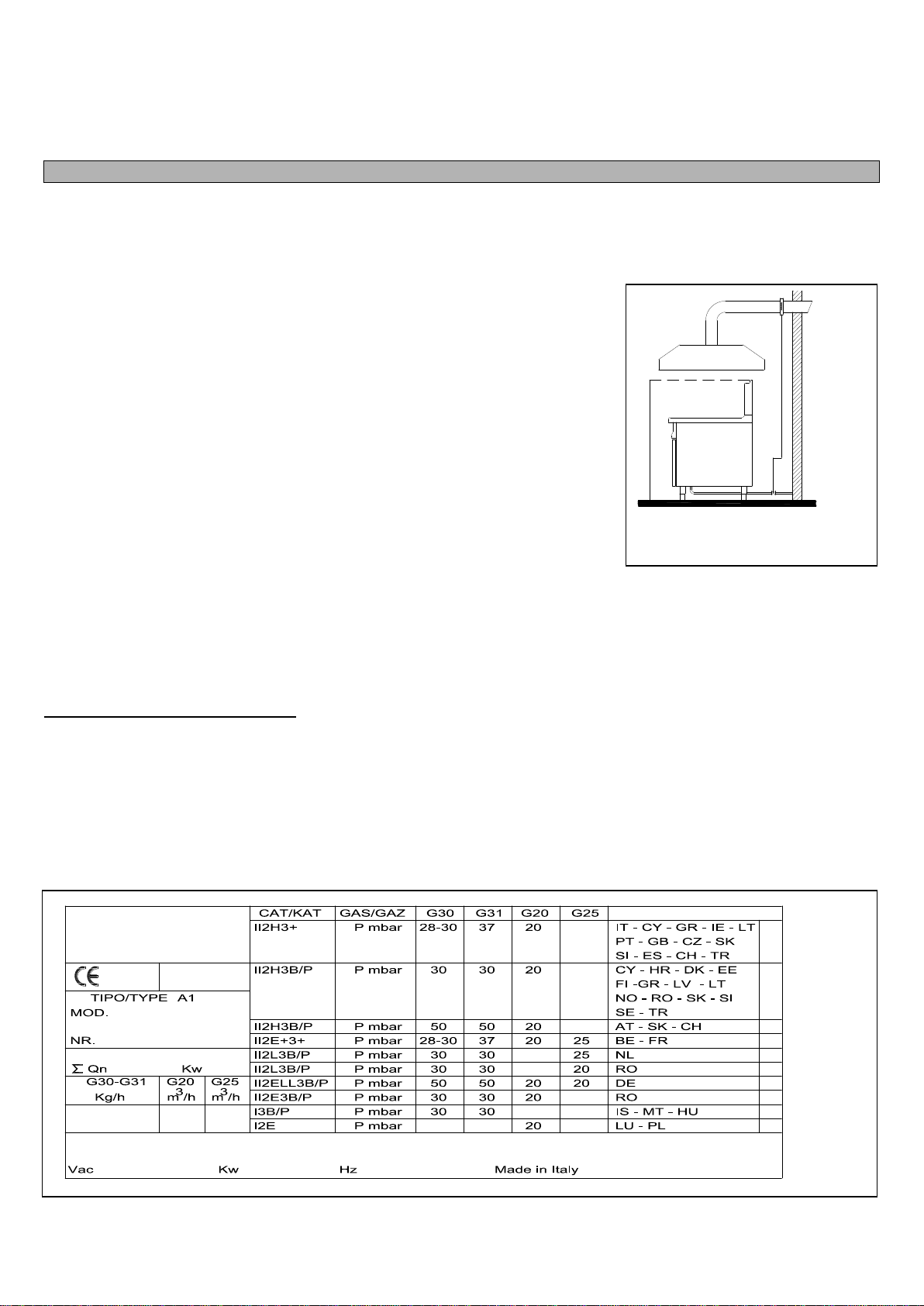
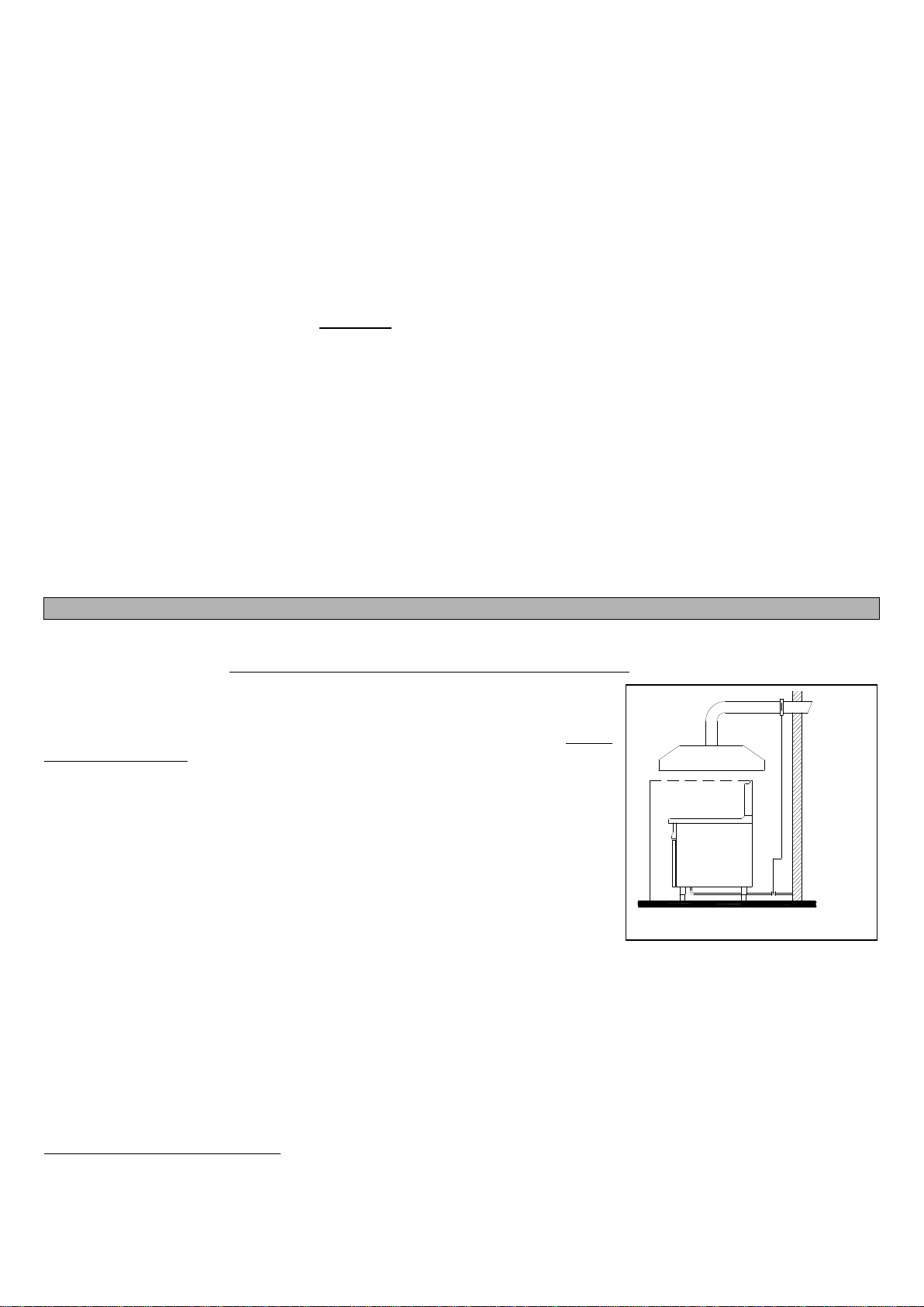
Evacuazione forzata sotto cappa. Nel caso di installazione sotto cappa, la parte terminale del condotto di scarico
sbocco dei condotti di scarico dei prodotti della combustione deve essere disposta entro il perimetro di base della cappa
forzata, e deve interrompersi nel caso che la portata di questo scenda sotto i valori prescritti dalla norma di installazione.
1,8 mt
Fig. 1
Evacuazione forzata sottocappa

3
Fig. 2
2.4 Collegamento gas
Controllare sulla targhetta tecnica (Fig. 2), posta nella parte interna o laterale
Controllare con i dati riportati sulla targhetta tecnica, che la portata del riduttore di pressione sia sufficiente per
onte
del regolatore di pressione al fine di garantire un funzionamento ottimale.
3. CARATTERISTICHE TECNICHE
-Apparecchio di categoria II2H3+
-no (G30-G31) 28-30/37mbar
TABELLA 1
MODELLO
DIMENSIONI
mm
(L x P)
RACCORDO
GAS
PORTATA
GAS
kW
CONSUMO
GAS
Kg/h
CONSUMO
GAS
m3/h
TIPO
SERIE STILE UNICO
SERIE STILE UNICO
400x730
800x730
1/2
7
14
0,55
1,10
0,74
1,48
A1
A1
SERIE 6 UNICO
SERIE 6 UNICO
350x630
700x630
1/2
6
12
0,47
0,95
0,63
1,27
A1
A1
TABELLA 2
PER APPARECCHI SERIE STILE UNICO 400x730x900H
PORTATA NOMINALE KW 7 PORTATA RIDOTTA KW 3
Iniettori
bruciatore
principale
Ø 1/100 mm
Iniettori spia
N°
By-pass
Ø 1/100 mm
Pos. aria primaria
bruc. principale
(misura in mm)
Gas liquidi
(G30 28...30mbar)
95*
24*
90
-
Gas naturali
(G20 20mbar)
140R*
29.2*
Regolabile
-
Per gli apparecchi serie STILE UNICO (800x700x900) con portata nominale 7 + 7 = 14 kw e portata ridotta
3 + 3 = 6 kw, gli iniettori sono 4.
TABELLA 3
PER APPARECCHI SERIE 6 UNICO 350x630x285H
PORTATA NOMINALE KW 6 PORTATA RIDOTTA KW 1,7
Iniettori
Bruciatore
Principale
Ø 1/100 mm
By-pass
Ø 1/100 mm
Pos. aria primaria
bruc. principale
(misura in mm)

4
Gas liquidi
(G30 28...30mbar)
125
70
4.0
Gas naturali
(G20 20mbar)
190
Regolabile
1.0
Per gli apparecchi serie 6 UNICO (700x630x285) con portata nominale 6 + 6 = 12 kw e portata ridotta 1,7 + 1,7=
3,4 kw, gli iniettori sono doppi.
TABELLA 4
MODELLO
SERIE STILE UNICO
DIMENSIONI
DIMENSIONI
PIASTRA
COMPOSIZIONE
PIASTRA
kW
U7F0TG40L
400x730x900
360x570
Liscia
7
U7F0TG80L
800x730x900
755x570
Liscia
14
U7F0TG80LR
800x730x900
755x570
Metà liscia / metà rigata
14
MODELLO
SERIE 6 UNICO
DIMENSIONI
DIMENSIONI
PIASTRA
COMPOSIZIONE
PIASTRA
kW
6UFTG35L
350x630x285
330x510
Liscia
6
6UFTG70L
700x630x285
680x510
Liscia
12
6UFTG70LR
700x630x285
680x510
Metà liscia / metà rigata
12
4. FUNZIONAMENTO CON GAS D’ALIMENTAZIONE IDENTICO A QUELLO PREDISPOSTO
Controllare se le indicazioni sulla targhetta segnaletica corrispondono al gas distribuito. Verificare inoltre la
corrispondenza di quanto qui di seguito riportato.
4.1 Controllo della pressione di alimentazione (Fig. 3)
La pressione di alimentazione può essere misurata a mezzo di manometro
-
-Posizionare il manometro.
-
in caso contrario accertarsi della causa.
-
ATTENZIONE: Se il valore della pressione di alimentazione misurato è esterno all’intervallo riportato nella tabella
5, non si può procedere all’installazione e bisogna informare l’ente erogatore del gas dell’anomalia della rete.
ione del gas, scollegare il misuratore di pressione, riavvitare la vite di chiusura e
chiudere il portello anteriore.
TABELLA 5 - Limiti ammissibili per la pressione di alimentazione del gas
Tipo di gas
Pressione di alimentazione [mbar]
nominale
minima
massima
Gas naturale (metano) G20
20
17
25
Gas liquido (GPL) G30/31
28 - 30/37
20/25
35/45
5. REGOLAZIONE PER FUNZIONAMENTO CON ALTRI TIPI DI GAS
Per eseguire tale operazione bisogna cambiare gli iniettori, regolare le portate ridotte, regolare la p
primaria come qui di seguito indicato. Dopo aver effettuato queste operazioni, applicare che indica il nuovo tipo
di gas (in dotazione con gli ugelli) sulla targhetta dati (fig. 1).
SERIE UNICO
5.1 Sostituzione dell’iniettore del bruciatore principale
5.2 Sostituzione dell’iniettore della fiamma pilota (Fig. 4)
Il bruciatore pilota è accessibile solo dopo aver tolto il pannello comandi.
liniettore secondo la tabella 2.
5.3 Regolazione dei minimi (Fig. 5)
ridotta indicata nella tabella 2. Verificare che la quantità di gas sia sufficiente per
mantenere un minimo stabile e resistente al passaggio portata massima/portata
minima.
SERIE 6 UNICO
5.4 Sostituzione dell’iniettore del bruciatore principale
B
A
Fig. 3
Fig. 4
Fig. 5

5
HG
Fig. 8
5.5 Regolazione dei minimi (Fig. 6)
portata ridotta indicata nella tabella 3. Verificare che la quantità di gas sia
sufficiente per mantenere un minimo stabile e resistente al passaggio
portata massima/portata minima.
6. ISTRUZIONI D’USO
Attenzione:
cucina professionale. Deve inoltre essere usato sotto sorveglianza e solamente per grigliare gli alimenti.
SERIE STILE UNICO - Accensione e spegnimento
6.1 Accensione della fiamma pilota (Fig. 7)
Premere la manopola e girarla verso sinistra fino alla posizione (accensione fiamma pilota).
fiamma pilota, non rilasciare la manopola e tenerla premuta per altri 10/20 secondi per scaldare la termocoppia.
La fiamma si può vedere dal foro spia che si trova sul pannello frontale. Nel caso la fiamma si spenga durante o dopo il
rilascio della manopola, ripetere .
6.2 Accensione bruciatore principale
Per accendere il bruciatore principale, girare la manopola
calorica desiderata per la cottura.
6.3 Spegnimento
Per spegnere il bruciatore principale, girare la manopola verso destra sulla posizione ; resterà accesa solo la fiamma
pilota. Se si continua a girare la manopola fino alla posizione , anche la fiamma pilota si spegnerà.
SERIE 6 UNICO - Accensione e spegnimento
6.4 Accensione del bruciatore principale (Fig. 8)
.
Una volta acceso il bruciatore continuare a tenere premuta la
manopola altri 10/20 secondi per permettere alla
termocoppia di scaldarsi.
La fiamma si può vedere dal foro spia che si trova sul
pannello frontale. Nel caso la fiamma si spenga durante o
dopo il rilas operazione.
Ruotare la manopola sulla temperatura desiderata.
6.5 Spegnimento
08).
7. MANUTENZIONE
Si consiglia di sottoscrivere un contratto di manutenzione annuale.
Pulire l con tela smeriglio; dopo la pulizi
cucina sulla superficie della piastra, per una sua migliore conservazione.
La pulizia delle parti in acciaio deve essere fatta accuratamente, utilizzando acqua tiepida. Se utilizzate sapone, o altri
detergenti
hio, o di funzionamento irregolare, è necessario chiudere il rubinetto principale di arrivo del gas e
chiamare il servizio tecnico.
Tutte le operazioni di manutenzione e di riparazione devono essere effettuate da un installatore abilitato.
1
2 Pilota
2 3 4 4 Min
3 Max
1 Spento
H
Fig. 7
Fig. 6

6
INSTRUCTIONS, USE AND MAINTENANCE HANDBOOK
GAS FRY-TOP 700 UNICO / 6 UNICO
Code 888670
Rev.00
05/2012
CONTENTS
1.
GENERAL INSTRUCTIONS
6
2.
INSTALLATION
7
2.1
Installation of the appliance
7
2.2
Installation
7
2.3
Fumes extraction
7
2.4
Connecting up gas
7
3.
TECHNICAL FEATURES
8
Table 1 (gas consumption)
8
Table 2 (UNICO burners)
8
Table 3 (6 UNICO burners)
8
Table 4 (UNICO and 6 UNICO SERIES)
8
4.
OPERATION WITH SUPPLY GAS IDENTICAL TO THAT AVAILABLE
8
4.1
Checking the supply pressure
8
5.
REGULATION FOR OPERATION WITH OTHER TYPES OF GAS
9
5.1
Replacing the injector of the main burner
9
5.2
Replacement of the injector of the pilot light
9
5.3
Adjusting the minimum
9
5.4
Replacing the injector of the main burner
9
5.5
Adjusting the minimum
9
6.
OPERATING INSTRUCTIONS
9
6.1
Pilot ignition
9
6.2
Turning on the main burner
10
6.3
Shutdown
10
6.4
10
6.5
Turning out the main burner
10
7.
MAINTENANCE
10
1. GENERAL INSTRUCTIONS
Read the instructions contained in this handbook carefully as they give important advice concerning safety of installation,
use and maintenance.
Keep this handbook for any further consultation by the various operators.
After having removed the packing, make sure the equipment is intact. In case of doubt, do not use the equipment and
contact professionally qualified staff.
Before connecting the equipment, make sure that the rating corresponds to that of the gas mains.
The equipment must only be used by staff trained in use of the same.
Before carrying out cleaning and maintenance, disconnect the equipment from the gas supply system.
Switch the equipment off in the case of a fault or malfunctioning. For any repairs only contact an authorised technical
service centre and request the use of original spare parts.
Failure to observe the above may jeopardise safety of the equipment.
Connection, installation of the system and appliances, ventilation and fumes extraction must be carried out according to
instructions, by professionally specialised staff, in accordance with the standards.
This equipment must only be used for the purpose for which it was specifically designed.
Do not wash the equipment with direct, high pressure jets of water.
Do not obstruct the openings or vents for extraction or release of heat.
So as to avoid the risk of rust or chemical attack in general, the stainless steel surfaces have to be kept properly clean.
Clean the parts in stainless steel daily with warm, soapy water, then rinse thoroughly and dry carefully.
On no account should the stainless steel be cleaned with steel wool pads, brushes or scrapers in standard steel, in that
they could deposit ferrous particles which, by oxidising, cause rust spots. Stainless steel wool can, if necessary, be used
in the direction of the satin finish.
the equipment long periods, close the gas valve and wipe all the steel surfaces vigorously with a cloth
moistened with Vaseline oil in order to apply a protective layer; also air the rooms periodically.
Before carrying out the connection, check on the technical data plate that the appliance has been tested and type-
Should the type of gas indicated on the plate not be
The manufacturer of the appliance declines every responsability for possible mistake contained in this booklet imputable
to printing or transcription errors. It also reserves the right to bring changes to the product if retains useful or necessary
without jeopardizing the essential characteristics.

7
1,8 mt
Fig. 1
Forced evacuation under hood
The manufacturing company declines any and every responsability if the rules brought in this manual are not strictly
observed.
The manufacturer of the appliance declines all responsibility for damage caused by faulty installation, tampering with the
appliance, improper use, poor maintenance, failure to observe local regulations and unskilled use.
THE DISCHARGE OF MACHINE WHEN OUT OF USE MUST BE DONE IN COMPLIANCE WITH LAW. THE MACHINE
MUST BE DELIVERED TO FIRM AUTHORIZED FOR THE DISCHARGE OF MACHINE AND OF ITS COMPONENTS.
2. INSTALLATION
2.1 Installation of the appliance
The operations of installation, any conversion for use with other types of gas, start-up and the remedying of any faults in
the systems, must only be carried out by qualified staff, in accordance with current laws.
The gas systems and the rooms where the appliances are installed must fulfil the regulations existing in the various areas
and in particular consideration must be made of the fact that the air required for combustion of the burners is equal to 2
m3/h per kW of installed power and that accident prevention regulations must be
observed.
2.2 Installation
Remove the appliances from the packing and position them in the place of use,
levelling them and regulating their height by means of the adjustable feet or other
means.
Remove the protective film from the external panels, detaching it slowly to prevent
the glue from remaining.
It is important that the walls adjacent to the appliance are protected against the
heat. Place refractory sheets in between them place the appliances at least 200
mm away from the side or rear walls.
2.3 Fumes extraction
The appliances must be installed in rooms suitable for the extraction of
combustion products, in accordance with the provisions of the installation
instructions. Our equipment is considered (see specifications table) as:
“A1” TYPE GAS APPLIANCES
The A type appliances must be installed in sufficiently ventilated places in order to
prevent the concentrations of harmful substances in the room where the unit is installed. They are not designed to be
connected to a discharge line of combustible materials. These appliances must discharge the combustible products into
the appropriate hoods, or similar devices, connected to a flue of proven efficiency, or they may be connected directly to
an outdoor vent.
Failing this, the use of an extractor fan is permitted, connected directly to an external area, with sufficient capacity, which
will then be increased by the exchange of air necessary for the welfare of the workers under current regulations,
approximately 35 m³/h for each kW of gas power installed.
Forced fume evacuation under hood
the floor on which the appliance stands (the ground), and the mouth of the combustion fume pipe must be inside the
same extractor hood (Fig. 1). The applia
former can be cut out in the event its capacity falls below that required by the law in force. It should only be possible to
2.4 Connecting up gas
Check on the rating plate (Fig. 2), under the fires on the left-hand side, that the appliance has been tested and approved
for the type of gas that the user uses.
Check that the nozzeles on the appliance are suitable for the available gas supply.
If gas supply pressure deviates by more than 10% from nominal pressure, fit a pressure regulator upstream of the
appliance to ensure that nominal pressure is maintained.
Do not reduce the diameter of the pipe between the reducer and the appliance.
Fig. 2

8
Fit a gas filter upstream of the pressure regulator in order to optimise operating efficiency.
3. TECHNICAL FEATURES
The data plate is positioned on the left of the cabinet.
- Appliance in category
- Supply pressure: Butane/Propane (G30-G31) 28-30/37mbar
Natural gas (G20) 20mbar
TABLE 1
MODELLO
DIMENSIONI
mm
(L x P)
RACCORDO
GAS
PORTATA
GAS
kW
CONSUMO
GAS
Kg/h
CONSUMO
GAS
m3/h
TIPO
UNICO SERIES
UNICO SERIES
400x730
800x730
7
14
0,55
1,10
0,74
1,48
A1
A1
6 UNICO SERIES
6 UNICO SERIES
350x630
700x630
6
12
0,47
0,95
0,63
1,27
A1
A1
TABLE 2
FOR UNICO SERIES APPLIANCES 400x730x900H
NOMINAL CAPACITY kW 7 REDUCED CAPACITY kW 3
Main burner
injectors
Ø 1/100 mm
Pilot light injectors
No.
By-pass
Ø 1/100 mm
Primary air pos.
main burner
(size in mm)
Liquid gas
(G30 28...30mbar)
95*
24*
90
-
Natural gas
(G20 20mbar)
140R*
29.2*
Adjustable
-
For appliances UNICO series (800x730x900H) with nominal capacity 7 + 7 = 14 kW and reduced capacity
3 + 3 = 6 kW the injectors are double.
TABLE 3
NOMINAL CAPACITY kW 6 REDUCED CAPACITY kW 1,7
Main burner
injectors
Ø 1/100 mm
By-pass
Ø 1/100 mm
Primary air pos.
main burner
(size in mm)
Liquid gas
(G30 28...30mbar)
125
70
4.0
Natural gas
(G20 20mbar)
190
Adjustable
1.0
For appliances series (700x630x285) with nominal capacity 6 + 6 = 12 kW and reduced capacity
1.7 + 1.7 = 3.4 kW the injectors are double.
TABLE 4
700 UNICO SERIES
DIMENSIONS
PLATEDIMENSIONS
PLATE COMPOSITION
kW
U70FTG40L
400x730x900
360x570
Smooth
7
U70FTG80L
800x730x900
755x570
Smooth
14
U70FTG80LR
800x730x900
755x570
Half smooth half scored
14
6 UNICO SERIES
DIMENSIONS
PLATEDIMENSIONS
PLATE COMPOSITION
kW
6UFTG35L
350x630x285
330x510
Smooth
6
6UFTG70L
700x630x285
680x510
Smooth
12
6UFTG70LR
700x630x285
680x510
Half smooth half scored
12
4. OPERATION WITH SUPPLY GAS IDENTICAL TO THAT AVAILABLE
Check whether the indications on the data plate correspond to the gas distributed.
Also check correspondence to the indications below.
4.1 Checking the supply pressure (Fig. 3)
The supply pressure can be measured by means of a pressure gauge with a
U-shaped pipe, or of the electronic type with a minimum grading of 0.1 mbar.
-
-Position the pressure gauge.
-Switch on the appliance and check that the pressure is the one intended:
otherwise check on the cause.
-At the end of the operations, reassemble the appliance and check the
connection.
B
A
Fig. 3

9
Fig. 4
Fig. 5
ATTENTION: If the pressure measurement is not within the thresholds stated in table 5, instead of installing the
appliance you should contact your gas provider to report a fault with your mains supply.
Close the gas valve, disconnect the pressure measurement device, do up the screw you had previously undone and
close the front panel.
TABLE 5 –Permissible thresholds for the gas feed pressure
Gas
Supply pressure [mbar]
nominal
min
max
Natural gas G20
20
17
25
Liquid gas G30/31
28 - 30/37
20/25
35/45
5. REGULATION FOR OPERATION WITH OTHER TYPES OF GAS
To do this we need to change the injectors, adjust the low flow rates, adjust the
position of the primary air as indicated below
After performing these operations, apply the 'sticker supplied with the nozzles
that indicates the new type of gas on the data plate (Fig. 2).
5.1 Replacing the injector of the main burner
To change the injector, remove the control panel; with a key CH 12 unscrew the
injector and replace it according Table 2.
5.2 Replacement of the injector of the pilot light (Fig. 4)
The pilot burner is only accessible after removing the panel. The pilot
injector is fixed and does not need any adjustment for the primary air. To
change the injector "D" loosen the fixing nut "E" and replace the injector
according to Table 2.
5.3 Adjusting the minimum (Fig. 5)
Adjust the minimum with a screwdriver from the screw "F" to obtain the
reduced flow rate indicated in Table 2. Verify that the amount of gas is
sufficient to maintain a minimum stable and resistant in the passage
maximum/minimum flow rate.
“6 UNICO” SERIES
5.4 Replacing the injector of the main burner
To change the injector, remove the control panel; unscrew the injector with a key CH 7 and replace according to table 3.
5.5 Adjusting the minimum (Fig. 6)
Adjust the minimum with a screwdriver from the screw "F" to obtain the reduced flow rate as indicated in Table 3. Verify
that the amount of gas is sufficient to maintain a minimum stable and resistant in the passage max/min flow rate.
6. OPERATING INSTRUCTIONS
Caution: before using the appliance the plate has to be cleaned with hot water.
The appliance has to be used by qualified staff, since it is an appliance intended solely for professional kitchens. It also
has to be used under supervision and only for grilling food.
“UNICO” SERIES - TURNING ON AND OFF
6.1 Pilot ignition (Fig. 7)
Press the knob and turn it to the left until the position "" (pilot ignition).
Hold down the knob and simultaneously press the button "H" of the burner ignition. After lighting the pilot, do not release
the knob and hold it for another 10-20 seconds to heat the thermocouple.
The flame can be seen from the hole indicator that is located on the front panel. If the flame goes out during or after the
release of the knob, repeat the operation.
Fig. 6

10
6.2 Turning on the main burner
To light the main burner, turn the knob to the left to position "max" (large flame), or directly to the position "minimum"
(small flame). Between these two positions you can choose the caloric flow rate desired for cooking.
6.3 Shutdown
To turn off the main burner, turn the knob to the right position ""; will stay on only the pilot light. If you continue to turn
the knob to the position "" even the pilot light will go off.
“6 UNICO” SERIES - TURNING ON AND OFF
6.4 Lighting the main burner (Fig. 7)
Press the knob "G" and turn to the left. Simultaneously press the "H" of the burner ignition. Once turned on the burner
continue to hold the knob other 10/20 seconds to allow the thermocouple to heat up. The flame can be seen from the hole
indicator that is located on the front panel. If the flame goes out during or after the release of the knob, repeat the
operation. Turn the knob to the desired temperature.
HG
Fig. 8
6.5 Turning out the main burner
Turn the knob to the position (Fig. 8).
7. MAINTENANCE
We recommend signing a maintenance contract at last once a year.
Clean the cooking plate after use with an emery cloth. After cleaning a thin layer of cooking oil has to be applied to the
plate surface in order to preserve it better.
The parts in stainless steel have to be cleaned gently, using warm water. If you use soap or detergent, make sure that
they do not contain abrasive products and that they are recommended for cleaning stainless steel.
If the appliance is not used for a certain period of time, close the gas supply cock. In the case of a fault in the appliance or
malfunctioning close the main gas inlet cock and call the technical service centre.
All repairs and fault remedying must be carried out by a skilled installer.
1
2 PILOT
2 3 4 4 MIN
3 MAX
1 OFF
Fig. 7

11
GRILLADES À GAZ (FRY-TOPS)
SÉRIES STILE UNICO ET 6 UNICO
NOTICE D’INSTALLATION, D’EMPLOI ET DE
MAINTENANCE
Cod. 888670
Rev. 00
03/2015
SOMMAIRE
1.
AVERTISSEMENTS GENERAUX
Pag. 11
2.
INSTALLATION
Pag. 12
2.1
Pag. 12
2.2
Pose des appareil
Pag. 12
2.3
Evacuation des fumées
Pag. 12
2.4
Raccordement du gaz
Pag. 12
3.
CARACTÉRISTIQUES TECHNIQUES
Pag. 13
Tableau 1 (consommation de gaz)
Pag. 13
Tableau 2 (caractéristiques techniques brûleur STILE UNICO)
Pag. 13
Tableau 3 (caractéristiques techniques brûleur 6 UNICO)
Pag. 13
Tableau 4 (fry-top STILE UNICO e 6 UNICO)
Pag. 13
4.
FONCTIONNEMENT AVEC LE MÊME GAZ QUE LE GAZ DISPONIBLE
Pag. 14
4.1
Pag. 14
5.
RÉGLAGE POUR FONCTIONNEMENT AVEC D’AUTRES TYPES DE GAZ
Pag. 14
STILE UNICO
Pag. 14
5.1
Remplacement des injecteurs des brûleurs principaux
Pag. 14
5.2
Pag. 14
5.3
Réglage du débit minimum
Pag. 14
5.4
Remplacement des injecteurs des brûleurs principaux
Pag. 14
5.5
Réglage du débit minimum
Pag. 15
6.
MODE D’EMPLOI
Pag. 15
6.1
Allumage de la veilleuse
Pag.15
6.2
Allumage du brûleur principal
Pag. 15
6.3
Extinction du brûleur principal
Pag. 15
6.4
Extinction totale
Pag. 15
6.5
Allumage du brûleur principal
Pag. 15
6.6
Extinction du brûleur principal
Pag.15
7.
ENTRETIEN
Pag.15
1. AVERTISSEMENTS GENERAUX
Lire attentivement les avertissements contenus dans cette notice dans la mesure où ils fournissent mportantes
Conserver cette notice de manière à ce que les différents opérateurs puissent la consulter à tout moment.
à du personnel professionnellement qualifié.
gaz.
doit être utilisé que par du personnel formé à cet effet.
Le non-respect de ce qui est précisé ci-
Le raccordement, la mise en service de l’installation et des appareils, l’aération et l’évacuation des fumées doivent être
effectués, selon les instructions du constructeur, par du personnel professionnellement spécialisé, conformément aux
normes en vigueur.
Cet appareil ne devra être de
inoxydable propres.
soin.

12
1,8 mt
Fig. 1
Evacuation forcée sous la hotte
Éviter absolument de net
s le sens du satinage.
protection; en outre, aérer périodiquement les locaux.
Avant de procéder au raccordement, contrôler sur la plaque signalétique que l’appareil a été testé et homologué pour le
type de gaz disponible chez l’utilisateur.
Au cas où le type de gaz indiqué sur la plaque ne serait pas celui distribué, suivre les indications du paragraphe
La société constructrice décline toutes responsabilites pour le possibles inexactitudes contenues dans cet opuscule
imputable a erreurs de transcriptions ou imprimeries. Elle reserve le droit de apporter a ses produits les modifiques que
retienne utile ou nécessaires, sans prejedicier les caractéristiques essentielles.
La société constructrice décline toutes responsabilites au cas auquel les normes contenues dans cet opuscule ne soient
strictement respectées.
tion impropre, un mauvais entretien, par le non-respect des normes
CONCERNANT LE MATERIEL USAGE, VOUS DEVEZ VOUS METTRE EN CONFORMITE SELON LES NORMES EN
VIGUEUR. LE MATERIEL DOIT ETRE REMIS A UN ORGANISME AUTORISE A LA COLLECTE ET TRAITEMENT.
2. INSTALLATION
2.1 Installation de l’appareil
ons ne doivent être accomplies que par du personnel qualifié, conformément
aux normes en vigueur.
3/h
par kW de puissance installée et que les Normes pour la prévention des accidents doivent être respectées.
2.2 Pose des appareil
procédant à leur mise à niveau et à leur réglage en hauteur en agissant sur les
Retirer des panneaux extérieurs la pellicule de protection en le détachant
lentement af
chaleur. Interposer des feuilles réfractaires ou bien installer les appareils à au
moins 200 mm des parois latérales ou arrières.
2.3 Evacuation des fumées
produits de la combustion qui doit se produire conformément aux normes
comme: APPAREILS A GAZ DE TYPE “A1”
Les appareils de type A1 doivent etre installes dans des locaux suffisamment
aeres pour prevenir la concentration de substances dangereuses pour la sante
tre raccordes a
bie
En son absence, il est possible d'utiliser un aspirateur d'air directement raccordé à l'extérieur, avec un débit non inférieur
aux nécessités, et qui doit être ensuite augmenté du renouvellement d'air nécessaire pour le bien-être des opérateurs
selon les normes en vigueur, indicativement pour un total de 35 m³/h pour chaque kW de puissance de gaz installée.
Evacuation forcée sous la hotte. En cas d'installation sous une hotte, l'extrémité du conduit d'évacuation de l'appareil doit
se trouver à au moins 1,8 m de la surface d'appui de l'appareil (sol); la section de sortie des conduits d'évacuation des
produits de la combustion doit être placée dans le périmètre de base de la hotte (Fig. 1). L'alimentation du gaz à l'appareil
doit être directement asservie au système d'évacuation forcée, et doit s'interrompre au cas où le débit de celui-ci descend
au-dessous des valeurs prescrites par la norme d'installation. Le retour de l'alimentation du gaz à l'appareil ne doit
pouvoir s'effectuer que manuellement.
2.4 Raccordement du gaz
Vérifier que les buses montées

13
Contrôler, sur les données reportées sur la plaquette technique, que le débit du réducteur de pression est suffisant pour
est conseillée de monter un filtre à gaz en amont du régulateur de pression.
3. CARACTÉRISTIQUES TECHNIQUES
La plaque signalétique est installé
-Appareil de catégorie II2E+3+
- : Butane/Propane (G30-G31) 28-30/37mbars
TABLEAU 1
MODÈLE
DIMENSIONS
mm
(L x L)
RACCORDEM
ENT GAZ
DÉBIT
GAZ
kW
CONSOMMATI
ON
Kg/h
CONSOMMATION
m3/h
TYPE
U70FTG40
U70FTG80
400x730
800x730
7
14
0,55
1,10
0,74
1,48
A1
A1
6UFTG40
6UFTG80
350x630
700x630
6
12
0,47
0,95
0,63
1,27
A1
A1
TABLEAU 2
POUR APPAREILS SÉRIE 700s 400x730x270/900
DÉBIT NOMINAL KW 7 DÉBIT MINIMUM KW 3
Injecteurs
Brûleur
principal
Ø 1/100 mm
Injecteurs
veilleuse
N°
By-pass
Ø 1/100 mm
Posit.air primaire
brûl. principal
(mesure en mm)
Gaz liquide
(G30 28...30mbar)
95*
24*
90
-
Gaz naturel
(G20)
140R*
29.2*
Réglable
-
Pour les appareils série 700s (800x700x270/900) avec débit nominal 7 + 7 = 14 kW et débit minimum 3 + 3 = 6 kW
les injecteurs sont doubles.
TABLEAU 3
POUR APPAREILS SÉRIE SERIE 6 UNICO 350x630x285H
DÉBIT NOMINAL KW 6 DÉBIT MINIMUM KW 1,7
Injecteurs
Brûleur
Principal
Ø 1/100 mm
Injecteurs
veilleuse
N°
By-pass
Ø 1/100 mm
Posit.air primaire
brûl. principal
(mesure en mm)
Gaz liquide
(G30 28...30mbar)
125
70
4.0
Gaz naturel
(G20)
190
Regolabile
1.0
Pour les appareils série 6 UNICO (700x630x285) avec débit nominal 6 + 6 = 12 kw et débit minimum 1,7 + 1,7= 3,4
Kw, les injecteurs sont doubles.
Fig. 2

14
B
A
Fig. 3
TABLEAU 4
MODÈLE SÉRIE STILE UNICO
DIMENSIONS
DIMENSIONS PLAQUE
COMPOSITION PLAQUE
KW
U7F0TG40L
400x730x900
360x570
Lisse
7
U70FTG80L
800x730x900
755x570
Lisse
14
U70FTG80LR
800x730x900
755x570
½ Lisse / ½ Nervurée
14
MODÈLE SÉRIE 6 UNICO
DIMENSIONS
DIMENSIONS PLAQUE
COMPOSITION PLAQUE
KW
6UFTG35L
350x630x285
330x510
Lisse
6
6UFTG70L
700x630x285
680x510
Lisse
12
6UFTG70LR
700x630x285
680x510
½ Lisse / ½ Nervurée
12
4. FONCTIONNEMENT AVEC LE MÊME GAZ QUE LE GAZ DISPONIBLE
Contrôler si les indications de la plaque signalétique correspondent au gaz distribué.
Vérifier en outre la correspondance de ce qui est reporté ci-dessous.
-
-Positionner le manomètre.
-soit celle prévue : dans le cas
contraire,en vérifier lacause.
-
ATTENTION: si la valeur de la pression d'alimentation mesurée est en dehors de l'intervalle reporté dans le
tableau 5, l'installation ne pourra pas être effectuée et il faudra informer de l'anomalie sur le réseau, l'entreprise
de distribution du gaz.
Fermer le robinet de sectionnement du gaz, débrancher le manomètre, revisser la vis de fermeture et refermer la
porte antérieure.
TABLEAU 5 - Limites admissibles de la pression d'alimentation du gaz
Gaz
Pression d’alimentation [mbar] BE - FR
nominal
min
max
Gaz naturel G20/G25
20/25
17/20
25/30
Gaz liquide G30/31
28 - 30/37
20/25
35/45
5. RÉGLAGE POUR FONCTIONNEMENT AVEC D’AUTRES TYPES DE GAZ
Pour accomplir cette opération, il faudra changer les injecteurs, régler les débits minimums, régler la position de l
primaire comme indiqué ci-dessous.
SÉRIE STILE UNICO
5.1 Remplacement des injecteurs du brûleur principal
2 et 3.
5.2 Remplacement de l’injecteur de la veilleuse (Fig. 4)
Pour accéder à la veilleuse, enlever le tableau des
ou 3.
5.3 Réglage du débit minimum (Fig. 5)
débit minimum indiqué dans le tableau 2. Vérifier que la quantité
de gaz est suffisante pour maintenir un minimum stable et
homogène, pour résister au passage débit maximum débit
minimum.
SÉRIE 6 UNICO
5.4 Remplacement des injecteurs du brûleur principal
avec u
Fig. 4
Fig. 5
Fig. 6

15
HG
Fig. 8
5.5 Réglage du débit minimum (Fig. 6)
débit minimum indiqué dans le tableau 3. Vérifier que la quantité
de gaz est suffisante pour maintenir un minimum stable et
homogène, pour résister au passage débit maximum débit
minimum.
6. MODE D’EMPLOI
Attention:
professionnelle. Il doit en outre être utilisé sous surveillance et seulement pour griller les aliments.
SÉRIE STILE UNICO
6.1 Allumage de la veilleuse (Fig. 7)
Appuyer sur la ma
fond pendant environ 10/20 secondes pour permettre le chauffage du thermocouple, après quoi la relâcher.
La flamme peut être observée par le regard qui se trouve sur le panneau avant. Si, durant ou après le relâchement de la
6.2 Allumage du brûleur principal
Pour allumer le brûleur principal, tournez le bouton vers la gauche jusqu'à la position "maximum" (grande flamme) ou
directement sur la position "minimum" (petite flamme). Entre ces deux positions, il est possible de choisir la puissance
désirée pour la cuisson.
6.3 Extinction du brûleur principal
6.4 Extinction totale
Pour éteindre la veilleuse et le brûleur principal, tourner la manette sur la position éteint. (Fig. 6)
SÉRIE 6 UNICO
6.5 Allumage du brûleur principal (Fig. 8)
sur la position allumage veilleuse. Tenir la manette
enfoncée et, en même temps, appuyer sur le bouton
la manette poussée à fond pendant environ 10/20
secondes pour permettre le chauffage du thermocouple,
après quoi la relâcher.
La flamme peut être observée par le regard qui se trouve
sur le panneau avant. Si, durant ou après le relâchement
6.6 Extinction totale
Pour éteindre la veilleuse 08).
7. ENTRETIEN
Nous conseillons de souscrire un contrat de maintenance au moins une fois par an.
Nettoyer la plaque après utilisation, avec de la toile émeri; après le nettoyage, il est nécessaire de passer une légère
face de la plaque, pour une meilleure conservation.
u
Toutes les opérations de réglage et de dépannage doivent être effectuées par un installateur agréé.
1
2 Pilota
2 3 4 4 Min
3 Max
1 Spento
H
Fig. 7

16
GAS-GRILLPLATTEN SERIE 700s UND 900s
BEDIENUNGS- UND WARTUNGSANLEITUNG
Cod. 888668
Rev. 04
05/2012
INHALT
1.
ALLGEMEINE HINWEISE
Pag. 16
2.
INSTALLATION
Pag. 17
2.1
Installation des gerätes
Pag. 17
2.2
Installation
Pag. 17
2.3
Rauchgasabführung
Pag. 17
2.4
Gasanschluss
Pag. 17
3.
TECHNISCHE DATEN
Pag. 18
Tabelle 1 (Gasverbrauch)
Pag. 18
Tabelle 2 (Technische angäbe für STILE UNICO)
Pag. 18
Tabelle 3 (Technische angäbe für SERIE 6 UNICO)
Pag. 18
Tabelle 4 (Griddleplatten SERIE STILE UNICO E 6 UNICO)
Pag. 18
4.
ARBEITSWEISE MIT EINER GASART
Pag. 19
4.1
Überprüfung des Förderdrucks
Pag. 19
5.
EINSTELLUNG FÜR DIE ARBEITSWEISE MIT ANDEREN GASARTEN
Pag. 19
5.1
Austausch der düse der Hauptbrenner
Pag. 19
5.2
Austausch der düse des Wachflammenbrenners
Pag.19
5.3
Einstellung der reduzierten Nennwärmebelastung
Pag. 19
5.4
Ersetzen des Hauptbrennerinjektors
Pag. 19
5.5
Anpassung der Minima
Pag. 19
6.
BEDIENUNGSHINWEISE
Pag. 20
6.1
Zündung des Wachflammenbrenners SERIE STILE UNICO
Pag. 20
6.2
Zündung des Hauptbrenners
Pag. 20
6.3
Ausschalten des Hauptbrenners
Pag. 20
6.4
Ausschalten beider Brenner SERIE 6 UNICO
Pag. 20
6.5
Stilllegung
Pag.20
7.
WARTUNG
Pag. 20
1. ALLGEMEINE HINWEISE
Das Handbuch ist vor der Inbetriebnahme des Gerätes aufmerksam durchzulesen, da es wichtige Hinweise in Bezug auf
eine fachgerechte Installation, die Bedienung und die Wartung desselben enthält.
Das Handbuch ist zwecks jeder weiteren Einsichtnahme seitens der Bediener sorgfältig aufzubewahren.
Das Gerät nach dem Auspacken auf eventuelle Schäden überprüfen. Im Zweifelsfall darf das Gerät nicht in Betrieb
genommen werden; wenden Sie sich bitte an qualifizierte Fachkräfte.
Bevor das Gerät angeschlossen wird, hat man sich zu vergewissern, dass die auf dem Geräteschild angegebenen Daten
mit denen des Gasversorgungsnetzes übereinstimmen.
Das Gerät darf nur von Personal bedient werden, das eingehend in dessen Arbeitsweise eingewiesen wurde.
Vor jeder Reinigung und vor der Durchführung von Wartungsarbeiten ist das Gerät vom Gasversorgungsnetz zu trennen.
Bei Auftreten von Betriebsstörungen oder einer nicht einwandfreien Arbeitsweise ist das Gerät auszuschalten. Für die
Durchführung von eventuellen Reparaturen wenden Sie sich bitte nur an eine autorisierte Kundendienststelle und
verlangen Sie Original-Ersatzteile.
Ein Nichtbefolgen des Obenbesagten kann die Betriebssicherheit des Gerätes beeinträchtigen.
Der Anschluss und die Installation der Anlage, der Geräte, der Belüftungsvorrichtungen sowie der Rauchgasabführungen
dürfen ausschließlich von qualifizierten Fachkräften unter Berücksichtigung der Angaben des Herstellers.
Das Gerät ist nur für den für ihn vorgesehenen Zweck bestimmt.
Für die Reinigung des Gerätes dürfen keine Hochdruckreiniger verwendet werden.
Die Ansaugschlitze oder Wärmeaustrittsöffnungen dürfen nicht bedeckt werden.
Zur Vermeidung einer Oxydation oder einer Einwirkung von Chemikalien sind die Edelstahloberflächen gut sauber zu
halten.
Die Edelstahloberflächen sind täglich mit lauwarmem Seifenwasser zu reinigen. Danach sind diese gut abzuspülen und
sorgfältig trocken zu reiben.
Für die Reinigung des Gerätes dürfen weder Stahlwolle, Stahlbürsten oder schaber verwendet werden, da sich
Eisenteilchen ablagern könnten, die durch ihre Oxydation eine Bildung von Rostflecken zur Folge haben. Eventuell kann
Edelstahlwolle verwendet werden, wobei bei der Reinigung auf die Richtung der Satinierung zu achten ist.
Wird das Gerät längere Zeit nicht in Betrieb genommen, ist der Gashahn zuzudrehen. Sämtliche Edelstahloberflächen
sind mit einem mit Vaselinöl getränkten Tuch kräftig einzureiben, wodurch ein Schutzfilm gebildet wird; ferner sind die
Räume in regelmäßigen Zeitabständen zu lüften.

17
1,8 mt
Abb. 1
Direkter Gebläse-Rauchabzug
Bevor das Gerät angeschlossen wird, ist auf dem Geräteschild zu überprüfen, ob das Gerät für die beim Benutzer zur
Verfügung stehende Gasart abgenommen und typgeprüft wurde.
Stimmt die auf dem Geräteschild angegebene Gasart nicht mit der zur Verfügung stehenden Gasart überein, sind die im
Die hestellfirma lehnt jegliche ungenanigkeiten in der vorliegenden broschure durch ubertragyngs oder druckfehler.
Siebehaltsichausserdem dasrecht vor, am Produkt Änderungen vorzunehmen, die sie für passend oder notwendig halt,
ohne dadurch seine Wesentuchen eigenshaften zu verändern.
Die hestellfirma lehnt jegliche Verantwortung ag. Wenn die in dieser Betriebsanleitung enthaltenen Vorschriften nicht
strengstens eingehalten werden.
Der Hersteller lehnt jede Verantwortung für Schäden ab, die auf eine nicht fachgerecht durchgeführte Installation, eine
Umrüstung des Gerätes, einen unsachgemäßen Gebrauch, eine mangelnde Wartung und ein Nichtbefolgen der örtlichen
Vorschriften zurückzuführen sind.
DIE ENTSORGUNG DER MASCHINE, AM ENDE DES ARBEITSZYKLUS, MUSS GEMÄß DEN
NORMFORSCHRIFTEN AUSGEFÜHRT WERDEN. DIE MASCHINE MUSS AN ERMÄCHTIGTES PERSONAL FÜR
DIE SAMMLUNG UND ENTSORGUNG DERSELBIGEN AUSGELIEFER WERDEN.
2. INSTALLATION
2.1 Installation des gerätes
Die Installation, eine eventuelle Anpassung an andere Gasarten, die Inbetriebnahme sowie die Behebung von eventuell
auftretenden Betriebsstörungen dürfen ausschließlich von qualifizierten Fachkräften unter Berücksichtigung der
geltenden Normen vorgenommen werden.
Die Gasanlagen und die Räume in denen die Geräte aufgestellt werden, müssen den für die unterschiedlichen Bereiche
geltenden Vorschriften entsprechend ausgelegt sein. Insbesondere ist darauf zu achten, dass die für die Verbrennung
erforderliche Luft der Brenner 2 m3/h pro kW der installierten Leistung beträgt. Ferner sind die
Unfallverhütungsvorschriften zu befolgen.
2.2 Installation
Die Geräte auspacken, am vorgesehenen Ort aufstellen, nivellieren und mit den verstellbaren Füßen o.a. auf die
gewünschte Höhe einstellen.
Den Schutzfilm von den äußeren Platten sorgfältig zur Vermeidung von Kleberückständen entfernen.
Wichtiger hinweis: Die angrenzenden Wände sind gegen die austretende Wärme zu schützen. Hierzu sind feuerfeste
Folien zwischenzufügen oder die Geräte in einem Abstand von mindestens 200
mm von den seitlichen oder hinteren Wänden aufzustellen.
2.3 Rauchgasabführung
Die Geräte sind in Räumen zu installieren, die für das Ableiten der Rauchgase
geeignet sind. Die Installation hat unter Berücksichtigung der diesbezüglichen
Normen zu erfolgen. Unsere Geräte gehören folgender Kategorie an (siehe
GASGERATE TYP “A1”
Die Gerate vom Typ A1 mussen in einem ausreichend belufteten Ambiente
aufgestellt werden, um die Konzentration von gesundheitsschadlichen
Substanzen im Installationsraum zu vermeiden. Fur sie ist kein Anschluss an
eine Abzugsleitung der Verbrennungsprodukte vorgesehen. Der Abzug der
Verbrennungsprodukte dieser Gerate muss uber entsprechende Hauben oder
ahnliche Vorrichtungen geschehen, die mit einem sicher arbeitenden Kamin
oder unmittelbar mit dem Ausenbereich verbunden sind.
In Ermangelung ist der Einsatz eines Luftsaugers zulässig, der direkt mit der
Außenumgebung verbunden ist. Sein Durchsatz darf nicht unter dem erforderten Durchsatz liegen. Er muss dann um die
Belüftung ergänzt werden, die notwendig ist für das Wohlbefinden der Bediener und in Entsprechung der geltenden
Vorschriften, also etwa insgesamt 35 m³/h je kW installiertes Gas.
Gebläse-Rauchabzug über Abzugshaube. Bei Installation unter einer Abzugshaube muss sich das Ende der
Abzugsleitung des Geräts mindestens 1,8 m über der Aufstellfläche des Geräts (Boden) befinden, der Auslass-
Querschnitt der Abzugsleitung der Verbrennungsprodukte muss innerhalb der Grundfläche der Abzugshaube angeordnet
sein (Abb. 1). Die Gaszufuhr zum Gerät muss direkt so mit dem Gebläse-Rauchabzug verschaltet sein, dass sie, wenn
die Abzugsleistung unter die von den Installationsbestimmungen vorgeschriebenen Werte sinkt, unterbrochen wird. Die
Wiederaufnahme der Gaszufuhr zum Gerät darf nur manuell möglich sein.
2.4 Gasanschluss
Auf dem Schild mit den technischen Daten (Abb. 2), dass sich an die Linken Seite, ob das Gerät für das dem Benutzer
zur Verfügung stehende Gas geprüft und freigegeben wurde.
Kontrollieren, ob die am Gerät montierten Düsen mit der zu Verfügung stehenden Gasart übereinstimmen.
Anhand des Schildes mit den technischen Daten kontrollieren, ob die Leistung des Druckreduzierers für die Speisung des
Gerätes ausreichend ist.
Keine Querschnittsverminderungen zwischen den Reduzierer und das Gerät schalten. Zur Gewährleistung eines
optimalen Betriebs wird geraten, dem Druckregler einen Gasfilter vorzuschalten

18
3. TECHNISCHE DATEN
Das Geräteschild ist am Boden des Gerätes angebracht.
-Gerätekategorie II2ELL3B/P
-Förderdruck: Butan/Propan (G30-G31) 50/50 mbar
Erdgas (G20-G25) 20/20 mbar)
TABELLE 1
MODELL
MASSE
cm (L x B)
GAS-
ANSCHLUSS
NENNWÄRMEBELASTUNG
kW
VERBRAUCH
Kg/h
VERBRAUCH
m3/h
TYP
U7FTG40
U7FTG80
400x730
800x730
7
14
0,55
1,10
0,74
1,48
A1
A1
6UFTG35
6UFTG70
350x630
700x630
6
12
0,47
0,95
0,63
1,27
A1
A1
TABELLE 2
FÜR GERÄTE SERIES 700 UNICO 400x730x900H
NENNWÄRMEBELASTUNG kW 7 REDUZIERTE NENNWÄRMEBELASTUNG kW 3
Düsen
Hauptbrenner
Ø 1/100 mm
Kontrolldüsen
Stck.
By-pass
Ø 1/100 mm
Pos. Primärluft
Hauptbrenner
(Maße in mm)
Flüssiggas
(G30 50mbar)
75R*
24*
90
-
Erdgas
(G20 20mbar)
140R*
29.2*
Adjustable
-
Die Geräte der Serie 700 UNICO (800x730x270/900) mit einer Nennwärmebelastung 7 + 7 = 14 kW und einer
reduzierten Nennwärmebelastung 3 + 3 = 6 kW sind mit doppelten Düsen ausgestattet.
TABELLE 3
FÜR GERÄTE SERIE 650 UNICO 350x630x285H
NENNWÄRMEBELASTUNG kW 6 REDUZIERTE NENNWÄRMEBELASTUNG kW 1.7
Düsen
Hauptbrenner
Ø 1/100 mm
By-pass
Ø 1/100 mm
Pos. Primärluft
Hauptbrenner
(Maße in mm)
Flüssiggas
(G30 50mbar)
110*
70
4.0
Erdgas
(G20 20mbar)
190*
Adjustable
1.0
Die Geräte der Serie 650 UNICO (700x630x285) mit einer Nennwärmebelastung 6 + 6 = 12 kW und einer
reduzierten Nennwärmebelastung 1.7 + 1.7 = 3.4 kW sind mit doppelten Düsen ausgestattet.
TABELLE 4
MODELL SERIE 700 UNICO
MASSE
MASSE BRATPLATTE
AUSFÜHRUNG BRATPLATTE
Kw
U70FTG40L
400x730x900
360x570
Smooth
7
U70FTG80L
800x730x900
755x570
Smooth
14
U7FTG80LR
800x730x900
755x570
Half smooth half scored
14
Abb. 2

19
MODELL SERIE 650 UNICO
MASSE
MASSE BRATPLATTE
AUSFÜHRUNG BRATPLATTE
Kw
6UFTG35L
350x630x285
330x510
Smooth
6
6UFTG70L
700x630x285
680x510
Smooth
12
6UFTG70LR
700x630x285
680x510
Half smooth half scored
12
4. ARBEITSWEISE MIT EINER GASART, DIE MIT DER ZUR VERFÜGUNG STEHENDEN
GASART ÜBEREINSTIMMT
Überprüfen, ob die auf dem Geräteschild angegebene Gasart mit der zur Verfügung stehenden Gasart übereinstimmt.
Ferner ist die Übereinstimmung mit den folgenden Angaben zu überprüfen.
4.1 Überprüfung des Förderdrucks (Abb. 3)
Der Förderdruck kann mittels eines Manometers mit U-Rohr oder eines
elektronischen Manometers mit einer Minimalaufteilung von 01, mbar
gemessen werden.
-
-Das Manometer positionieren.
-Das Gerät in Betrieb nehmen und überprüfen, ob der Druck mit den
vorgegebenen Werten übereinstimmt. Ist dies nicht Fall, ist die Ursache
zu ermitteln.
-Danach ist das Gerät erneut zu montieren und der Anschluss zu überprüfen.
ACHTUNG: Wenn der gemessene Wert des Versorgungsdrucks außerhalb des in Tabelle 5 angegebenen
Intervalls liegt, darf die Installation nicht erfolgen und die Gasversorgungsanstalt ist über die Störung des Netzes
zu informieren.
Gasabsperrhahn zudrehen, Druckmessgerät abklemmen, Verschlussschraube wieder einschrauben und Vordertür
schließen.
TABELLE 5 - Zulässige Grenzwerte für den Gasversorgungsdruck
Gas
Förderdrucks [mbar] DE
nominal
min
max
Flüssiggas G20
20
17
25
Flüssiggas G25
20
17
25
Erdgas G30/G31
50/50
42,5/42,5
57,5/57,5
5. EINSTELLUNG FÜR DEN BETRIEB MIT ANDEREN GAS
Um diesen Vorgang durchzuführen, müssen die Injektoren gewechselt, die reduzierten Flussraten eingestellt und die
Primärluftposition wie unten angegeben eingestellt werden.
Nach Durchführung dieser Arbeiten, den Klebstoff mit der neuen Gasart (mit den Düsen enthalten) auf das Typenschild
auftragen (Abb. 1).
UNICO SERIE
5.1 Austausch des Hauptbrennerinjektors
Um den Injektor zu wechseln, entfernen
Sie das Bedienfeld; schrauben Sie den Injektor mit einem
CH 12 Schlüssel ab und ersetzen Sie ihn gemäß Tabelle 2.
5.2 Austausch des Pilotflammeninjektors (Abb. 4)
Der Pilotbrenner ist nur nach der Entfernung des Bedienfeldes zugänglich.
Der Pilot-Injektor ist fest und es ist keine Einstellung für Primärluft erforderlich.
Um den Injektor "D" zu wechseln, schrauben Sie die Befestigungsmutter
"E" ab und ersetzen Sie den Injektor gemäß Tabelle 2.
5.3 Anpassung der Minima (Abb. 5)
Stellen Sie das Minimum mit einem Schraubenzieher
von der "F" -Schraube ein, um die in Tabelle 2 angegebene
reduzierte Durchflussrate zu erhalten.
Überprüfen Sie, dass die Gasmenge ausreicht, um ein Minimum stabil
und beständig gegen den maximalen
Durchfluss / Mindestdurchfluss zu halten.
SERIE 6 UNICO
5.4 Austausch des Hauptbrennerinjektors
Um den Injektor zu wechseln, entfernen Sie das Bedienfeld; schrauben Sie den
den Injektor mit einem CH 7 Schlüssel ab und ersetzen Sie ihn gemäß Tabelle 3.
5.5 Anpassung der Minima (Abb. 6)
Stellen Sie das Minimum mit einem Schraubenzieher von der "F"
-Schraube ein, um die in Tabelle 3 angegebene reduzierte
Durchflussrate zu erhalten. Überprüfen Sie, dass die Gasmenge
ausreicht, um ein Minimum stabil und beständig gegen den
maximalen Durchfluss / Mindestdurchfluss zu halten.
B
A
Abb. 3
Fig. 4
Fig. 5
Fig. 6

20
6. BEDIENUNGSHINWEISE
Achtung: Vor der ersten Inbetriebnahme des Gerätes ist die Bratplatte mit warmem Wasser zu reinigen. Das Gerät darf
nur von qualifiziertem Personal bedient werden, da es sich um ein Gerät handelt, das ausschließlich in einer Großküche
eingesetzt wird. Ferner ist das Gerät während des Betriebs zu überwachen und nur zum Grillen von Lebensmitteln
benutzbar.
6.1 Zündung des Wachflammenbrenners / der Pilotsflammen (Abb. 7)
Drücken Sie den Knopf und drehen Sie ihn nach links in die Position (Zündflamme Zündung).
Halten Sie den Knopf gedrückt und drücken Sie gleichzeitig die "H" -Taste an der Zündung. Nach dem Einschalten der
Zündflamme, den Knopf nicht loslassen sondern weitere 10/20 Sekunden lang halten, um das Thermoelement zu
erwärmen.
Die Flamme ist an der Kontrollleuchte auf der Vorderseite erkennbar. Falls die Flamme während oder nach dem
Loslassen des Knopfes erlischt, wiederholen Sie den Vorgang.
6.2 Zündung des Hauptbrenners
Um den Hauptbrenner einzuschalten, drehen Sie den Knopf nach links auf die Position "Maximum" (große Flamme) oder
direkt auf die Position "Minimum" (kleine Flamme). Zwischen diesen beiden Positionen kann der gewünschte Kalorie
Einfluss zum Kochen gewählt werden.
6.3 Ausschalten
Um den Hauptbrenner auszuschalten, drehen Sie den Knopf in der Position nach rechts; nur die Zündflamme leuchtet
weiter. Wenn Sie den Knopf weiterhin in die Position drehen, wird auch die Pilotflamme ausgeschaltet.
SERIE 6 UNICO - Ein- und Ausschalten
6.4 Einschalten des Hauptbrenners (Abb. 8)
Drücken Sie den Knopf "G" und drehen Sie ihn
nach links. Drücken Sie gleichzeitig die "H" -Taste
an der Zündung. Wenn der Brenner eingeschaltet
ist, den Knopf für weitere 10/20 Sekunden
gedrückt halten, damit sich das Thermoelement
erhitzen kann.
Die Flamme ist an der Kontrollleuchte auf der
Vorderseite erkennbar. Falls die Flamme während
oder nach dem Loslassen des Knopfes erlischt,
wiederholen Sie den Vorgang.
Drehen Sie den Knopf auf die gewünschte
Temperatur.
Ausschalten beider Brenner
Um den Hauptbrenner auszuschalten, drehen Sie
den Knopf auf die Position "0" (Abb. 8).
7. WARTUNG
Es empfiehlt sich, mindestens einmal pro Jahr einen Wartungsvertrag zu unterzeichnen.
Die Bratplatte nach dem Gebrauch mit Schleifleinen reinigen; nach erfolgter Reinigung ist die Bratplatte mit etwas
Küchenöl zu bestreichen für bessere Bewahrung.
Sämtliche Teile aus Edelstahl sind sorgfältig mit lauwarmem Wasser zu reinigen. Wird Seife oder Reinigungsmittel
verwendet, hat man sich zu vergewissern, dass diese keine Schleifmittel enthalten und dass sie für die Reinigung von
Edelstahl geeignet sind.
Wird das Gerät längere Zeit nicht in Betrieb genommen, ist der Gashahn zuzudrehen. Im Falle einer Betriebsstörung oder
einer unregelmäßigen Arbeitsweise des Gerätes ist der Hauptgashahn zuzudrehen und den Kundendienst zu
verständigen.
Reparaturen dürfen ausschließlich von einem fachkundigen Installateur vorgenommen werden.
1
2 Pilota
2 3 4 4 Min
3 Max
1 Spento
H
Fig. 7
HG
Abb. 8
This manual suits for next models
8
Table of contents
Languages:
Other OFFCAR Commercial Food Equipment manuals
Popular Commercial Food Equipment manuals by other brands

Hoshizaki
Hoshizaki ROX-20TB2-U instruction manual

Aqua Computer
Aqua Computer cuplex kryos NEXT RGBpx Operating and assembly manual

Janssen
Janssen F Series operating instructions

Lotus
Lotus LIBR.ISTR.CW110G Installation and operating instructions

APW Wyott
APW Wyott TM-90 Wiring diagram

Sagi
Sagi 51H Series Use and installation manual