True GDM-HST02-HC-TSL01 User manual

TEC_TM_158 | REV. B | EN 12/4/2023
INSTALLATION MANUAL
GDM-HST02-HC~TSL01
True Manufacturing Co., Inc.
INSTALLATION MANUAL
GDM-HST02-HC~TSL01
Original Instructions
True Manufacturing Co., Inc.
2001 East Terra Lane • O’Fallon, Missouri 63366-4434
(636) 240-2400 • FAX: (636)-272-2408
International FAX: (636)-272-7546 • (800)-325-6152
Parts Department: (800)-424-TRUE (424-8783)
Parts Department FAX: (636)-272-9471
North America – Canada and Caribbean
Warranty Phone +1 855- 878-9277
Warranty Fax +1 636-980-8510
Technical Phone +1 855-372-1368
Technical Email service@truemfg.com
7:00 am–6:00 pm CST Monday–Friday,
8:00 am–12:00 pm Saturday
UK, Ireland, Middle East,
Africa & India
Phone: +44 (0) 800-783-2049
Service-[email protected]
8:30 am–5:00 pm M–F
European Union & Commonwealth
of Independent States
Phone: + 41 61 563 0705
service-[email protected]
8:00 am–5:00 pm M–F
Australia
Phone: +61 2-9618-9999
8:30 am–5:00 pm M–F
Mexico
Phone +52 555-804-6343/44
service-[email protected]
9:00 am–5:30 pm M–F
Latin America
Phone: +52 555-804-6343/44
9:00 am–5:30 pm M–F
USER ACTION!
TRUE tracks the history of your appliance by its serial number.
For easy reference, record your appliances full model name and
serial number below. This information is on your serial label.
Serial label location varies by appliance.
Model Name:
Serial Number:
WARNING!
Be sure to read and fully understand this document
before installing, operating, maintaining or servicing
this appliance. Failure to do so can result in appliance
failure, property damage, serious injury or death.
Appliance failure, injury or property damage due to
improper installation is not covered by warranty.
GDM-23-HST02-HC~TSL01 GDM-26-HST02-HC~TSL01

GDM-HST02 truemfg.com
TEC_TM_158 | REV. B | ENP#84066912/4/2023Page 2 of 48
Preface
Signal & Symbol Definitions..............................................................3
Important Safety Information
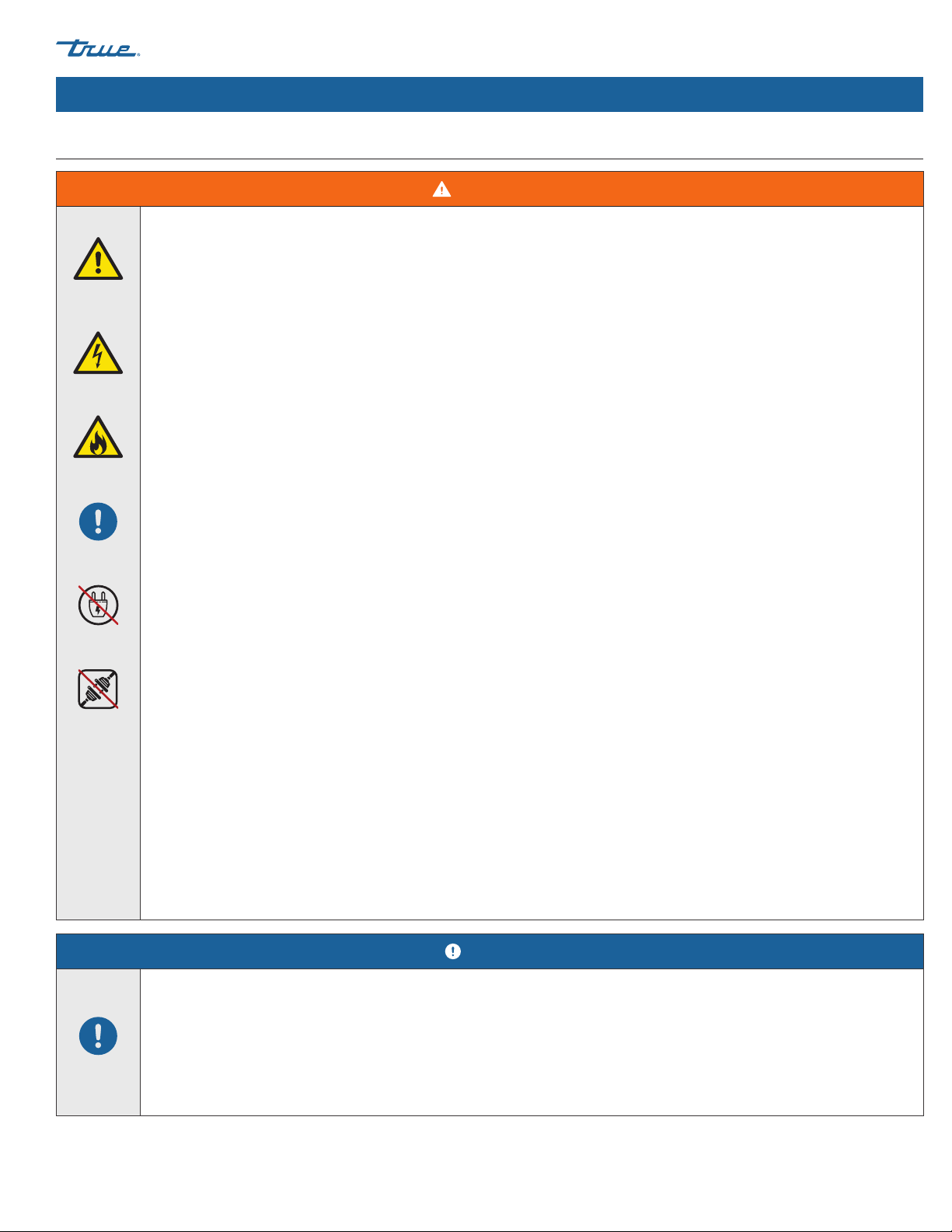
Basic Safety & Operation Warnings...............................................5
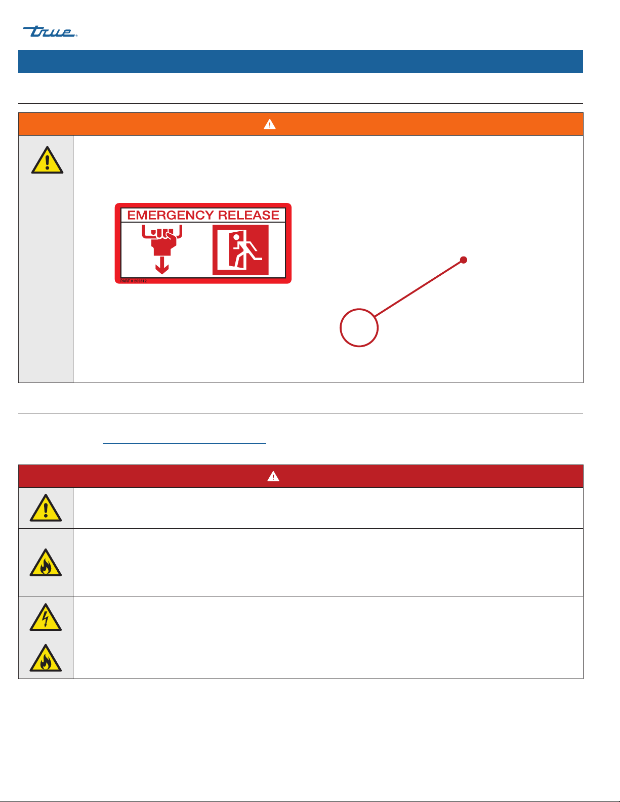
Emergency Release Pull Cord Operation..................................6
Personal Injury Warnings.....................................................................6
Appliance Disposal Warnings...........................................................8
Hydrocarbon Refrigerant Warnings..............................................8
Electrical Safety Warnings...................................................................9
About Your Appliance & Installation Requirements
Appliance Specifications ..................................................................11
Clearances.................................................................................................. 12
Electrical Requirements..................................................................... 13
Electrical Installation & Safety........................................................13
Wiring Instruction Advisement (115V only) .........................14
Installation & Setup
Uncrating.................................................................................................... 15
Appliance Location..............................................................................17
Leveling Screw, Leg or Castor Installation............................. 17
Level the Appliance.............................................................................19
Sealing the Appliance to the Floor............................................ 19
Shelf Installation..................................................................................... 20
Battery Backup........................................................................................21
Appliance Operation
Startup.......................................................................................................... 23
Temperature Control & Light Switch Location...................23
Sequence of Operation..................................................................... 24
Health Safety Timer (HST)................................................................ 25
Electronic Temperature Control
Display Codes..........................................................................................27
Lock / Unlock the Control................................................................ 28
Turn Off / On the Control................................................................. 28
Lock / Unlock the Door – Button Combo............................. 29
Lock / Unlock the Door – Password Entry.............................29
Enable the Product Loading & Servicing Delay................. 30
Test the Health Safety Lock.............................................................30
Clear the Health Safety Alarm or Product
Loading & Servicing Delay............................................................31
Silence the Door Open Alarm.......................................................31
Change the Set Point..........................................................................32
Initiate Manual Defrost ......................................................................32
Change Frost Intervals .......................................................................33
Change Display Readout.................................................................. 33
Display Probe Temperatures........................................................... 34
Maintenance & Servicing
Component Replacement............................................................... 37
Recommended Maintenance .......................................................38
Condenser Coil Cleaning.................................................................. 40
General Surface Care & Cleaning................................................ 42
Stainless Steel Care & Cleaning.................................................... 43
8 Tips to Help Prevent Rust on Stainless Steel.................... 44
Warranty
Warranty Information..........................................................................45
THANK YOU
FOR YOUR PURCHASE
Congratulations!
The primary purpose of this document is to assist the installation, maintenance, and servicing of your TRUE appliance.
This document contains information important to safety, operation, maintenance, and servicing. DO NOT discard this
document. TRUE is solely the appliance manufacturer. For assistance finding a qualified technician, please visit our
Service Company Locator at truemfg.com/support/service-locator.
Contents
NOTICE!
Your appliance may not exactly match the figures shown in this manual.

GDM-HST02
TEC_TM_158 | REV. B | EN 12/4/2023 Page 3 of 48
truemfg.com
Preface
The warning, guidelines, and recommendations within this document are meant to prevent appliance damage, injury, or death. Please
carefully read all warnings, guidelines, and recommendations before proceeding to ensure the continued safe use and maintenance of
your TRUE appliance.
Signal & Symbol Definitions
Below are symbols you may see in this document. Some symbols may not appear.
Signal Word Definitions
DANGER! An imminently hazardous situation which, if not avoided, will result in serious injury or death.
WARNING! A potentially hazardous situation which, if not avoided, can result in serious injury or death.
CAUTION! A potentially hazardous situation which, if not avoided, may result in minor or moderate injury;
an unsafe practice.
USER ACTION! User action alert, follow all recommendations to avoid appliance or product damage.
NOTICE! Important information not related to hazards or risk of personal injury.
Safety Symbols
Safety alert; alerts reader to potential physical
injury hazards. Obey all safety messages following
this symbol to avoid possible injury or death.
Flammable material; fire hazard.
Electrical shock hazard.
Tipping hazard; tip-over hazard.
Sharp element; cut or sever hazard.
Eye hazard; risk of eye injury.
Exploding pressurized cylinder hazard.
Slippery surface hazard.
Crush or cut hazard.
Additional Symbols
Mandatory action alert symbol; alerts reader
to required or recommended actions. Obey all
messages and recommendations following this
symbol to avoid appliance or product damage.
NOTICE ›Important information not related to hazards or
risk of personal injury.
Review and understand the installation manual
before installing, operating, or servicing.
Wear eye protection.
Wear protective gloves.
Secure gas cylinders to prevent falling cylinders.
DO NOT use extension cord.
DO NOT use adaptor plugs.
DO NOT dispose of with other household waste.

GDM-HST02 truemfg.com
TEC_TM_158 | REV. B | ENP#84066912/4/2023Page 4 of 48
NOTES

GDM-HST02
TEC_TM_158 | REV. B | EN 12/4/2023 Page 5 of 48
truemfg.com
Important Safety Information
WARNING!
`
Be sure to read and fully understand this document before installing, operating, maintaining, or servicing this appliance.
Failure to do so can result in appliance failure, property damage, serious injury, or death. Appliance failure, personal
injury, or property damage due to improper installation is not covered by warranty.
• Failure to install, operate, and maintain the appliance as detailed in this document will negatively affect safety, appliance
performance, component life, and warranty coverage.
• The appliance must be installed in accordance with all applicable laws, codes, and regulations.
• The manufacturer cannot be held responsible for injury or damage resulting from improper, incorrect, and unreasonable
use.
• This appliance is not to be used, cleaned, or maintained by persons (including children) with reduced physical, sensory, or
mental capabilities or lack of experience and knowledge, without proper supervision or instruction.
• DO NOT install or operate equipment that has been misused, abused, neglected, damaged, or altered/modified from
original manufactured specifications.
• DO NOT modify or alter the appliance. Improper alterations can result in electric shock, personal injury, fire, or death.
• DO NOT use electrical appliances inside the food storage compartments of the appliance unless the appliances are
approved by the manufacturer.
• The appliance owner is responsible for performing a Personal Protective Equipment (PPE) Hazard Assessment and to ensure
adequate protection during maintenance and cleaning procedures.
• Use appropriate tools, safety equipment, and PPE during installation and servicing.
• Only use the appliance for its intended purpose as described in this document. Failure to do so may result in equipment
damage, personal injury, or death.
• Overloading, incorrectly installing, or improperly loading shelves can cause shelf failure (as well as negatively affect the
appliance's operation), resulting in appliance damage, product damage, or personal injury.
• Keep the area surrounding the appliance clean to avoid appliance damage from debris or pests.
Important Safety Information
Basic Safety & Operation Warnings
Follow basic safety precautions, including the following, to reduce risk of personal injury, electric shock, fire, or death.

GDM-HST02 truemfg.com
TEC_TM_158 | REV. B | ENP#84066912/4/2023Page 6 of 48
Important Safety Information (cont.)
WARNING!
`
Risk of Entrapment. In case of emergency, the door may be unlocked and opened from the inside with the pull cord.
The emergency release pull cord is located near the Emergency Release sticker on the inner sidewall of the appliance.
See figs. 1 and 2.
Emergency Release Pull Cord Operation
Fig. 1. Emergency release identification sticker. Found
on inner sidewall of the appliance.
Fig. 2. Emergency release cord location.
Personal Injury Warnings
Only qualified technicians should install and service the appliance. For assistance finding a qualified technician, please visit our Service
Company Locator at truemfg.com/support/service-locator. TRUE is solely the appliance manufacturer and is not responsible for
installation.
DANGER!
DO NOT allow children to play with or in the appliance. Child entrapment or personal injury can occur.
DO NOT store or use the following in the vicinity of this or any other appliance:
• Gasoline or other flammable vapors and liquids
• Combustible or explosive substances, such as aerosol cans with a flammable propellant
• Other volatile or flammable substances
Contact TRUE Manufacturing to locate refrigerant lines and electrical wiring before drilling, cutting or puncturing interior
or exterior walls. Failure to do so could result in damage, personal injury, or death.

GDM-HST02
TEC_TM_158 | REV. B | EN 12/4/2023 Page 7 of 48
truemfg.com
Important Safety Information (cont.)
WARNING!
Only qualified technicians should install and service the appliance.
• Use appropriate tools, safety equipment, and personal protective equipment (PPE) during installation and servicing.
• DO NOT touch the cold surfaces in the freezer compartment when hands are damp or wet. Skin may stick to extremely cold
surfaces.
This product can expose you to chemicals including Di-(2-Ethyl hexyl) Phthalate (DEHP), which is known to the State of
California to cause cancer and birth defects or other reproductive harm. For more information go to P65warnings.ca.gov.
Slippery Surfaces! Moisture from improper drainage can create slippery surfaces near the appliance. It is your duty to
immediately warn your customers of, and dry, the slippery surface. All wet floor areas must be marked with a wet floor sign.
Sharp edges! Take care when moving, installing, cleaning, servicing, and maintaining the appliance to avoid cuts. Be sure to
take care when reaching under the appliance or handling metal components.
• Keep fingers out of pinch point areas, such as the space between appliance doors and surrounding cabinetry. Take care
closing doors with children nearby.
Tip over hazard! Appliance may pose a tipping hazard when uncrating, installing, or moving the appliance. Take appropriate
safety precautions. Use of tip over restraints may only reduce (not eliminate) the tipping hazard. Never allow children to climb
or hang on drawers, doors, or shelves.
Crush or cut hazard! Keep clear when uncrating, installing, moving, or servicing the appliance.
Risk of electric shock or burn! See "Electrical Safety Warnings" for more information.
Personal Injury Warnings (cont.)
Only qualified technicians should install and service the appliance. For assistance finding a qualified technician, please visit our Service
Company Locator at truemfg.com/support/service-locator. TRUE is solely the appliance manufacturer and is not responsible for
installation.

GDM-HST02 truemfg.com
TEC_TM_158 | REV. B | ENP#84066912/4/2023Page 8 of 48
Important Safety Information (cont.)
DANGER!
Risk of fire or explosion! Flammable refrigerant used.
• All servicing and maintenance must be performed by qualified technicians. This is to minimize the risk of fire or personal
injury due to incorrect parts or improper service.
• Check the serial label to identify the appliance's refrigerant. Serial label location varies by model.
• DO NOT damage the refrigeration system during transportation and installation.
• If the appliance is damaged, verify the refrigeration system's integrity is not compromised before proceeding.
• Never use sharp objects or tools to remove ice or frost. DO NOT use mechanical devices to accelerate defrost.
• Dispose of in accordance with all applicable laws, codes, and regulations. Follow all safety precautions associated with
handling flammable refrigerant.
• DO NOT use electrical appliances inside the food storage compartments of the appliances unless the appliances are of the
type recommended by the manufacturer.
DANGER!
Risk of child entrapment!
Children can get trapped inside discarded appliances and suffocate. Never dispose
of your appliance without taking precautions to prevent child entrapment, even
if the appliance only sits unattended for a short period of time.
Child entrapment precautions include the following:
• Remove all doors (or drawers for drawer appliances).
• Leave all interior drawers and shelving in place to make climbing (and fitting)
inside the appliance more difficult.
Risk of fire or explosion! Flammable refrigerant and insulation used. Dispose of in accordance with all applicable laws, codes,
and regulations. Follow all safety precautions associated with handling flammable refrigerant and insulation.
DO NOT dispose of your appliance with household waste.
Hydrocarbon Refrigerant Warnings
TRUE appliances use hydrocarbon refrigerant (R-290/513A/600a). Check the serial label to identify the appliance's refrigerant. Serial label
location varies by model.
Appliance Disposal Warnings

GDM-HST02
TEC_TM_158 | REV. B | EN 12/4/2023 Page 9 of 48
truemfg.com
Important Safety Information (cont.)
WARNING!
Risk of electric shock, burn, or fire!
• It is the appliance owner's responsibility to ensure the electrical connection meets all applicable building codes. Failure
to meet these code requirements can result in appliance damage, fire, electric shock or burns, serious personal injury, or
death.
• Before connecting your appliance to the power supply, verify the supply voltage and circuit rating match the appliance.
Correct improper supply voltage or circuit size immediately.
• Before connecting your appliance to the power supply, verify the power supply is correctly grounded. If the power supply
is not grounded, correct immediately. TRUE recommends hiring a qualified electrician to inspect your wall outlet and circuit
to ensure they are properly grounded.
• DO NOT clean appliance with a pressure washer or hose. DO NOT immerse power cord in water.
• Powering off an electronic control or setting temperature controls to 0 (off position) does not remove power from all
components. Unplug the appliance or turn off the power supply before installation or servicing.
• The appliance should receive power from its own individual dedicated electrical circuit. This provides the best performance
and prevents overloading the power supply.
• The original equipment manufacturer (OEM) power cord has a grounding plug to minimize the possibility of electrical
shock.
• Never remove the ground prong from the power cord! For personal safety, this appliance must be properly grounded.
• Never use an extension cord! An extension cord is any component that adds length to the OEM power cord when
connecting the cord to a power source.
• Never use an adapter plug! An adapter plug alters the OEM plug configuration when connecting the plug to a power
source.
• Never use a power cord that shows cracks or abrasion damage along its length or at either end.
• Immediately have a qualified technician replace damaged OEM power cords with OEM components.
• Never unplug your appliance by pulling on the power cord. Always grip the plug and pull the plug straight out of the
outlet.
• Take care to prevent rolling over or damaging the power cord when moving the appliance.
• Never use the power cord to prevent appliance movement. Always use adequate means to keep the appliance in place
without transmitting stress to the power cord.
• Keep power cord away from heated surfaces.
• DO NOT let power cord hang over edge of table or counter.
• DO NOT excessively bend or place heavy articles on the power cord.
NOTICE!
TRUE will not warranty the following:
• Compressor failures due to improper incoming voltage.
• Appliance with tampered OEM power cords.
• Appliance connected to adapters or extension cords.
For more details, see TRUE's full warranty statement.
Electrical Safety Warnings

GDM-HST02 truemfg.com
TEC_TM_158 | REV. B | ENP#84066912/4/2023Page 10 of 48
NOTES

GDM-HST02
TEC_TM_158 | REV. B | EN 12/4/2023 Page 11 of 48
truemfg.com
Thank you for choosing TRUE Manufacturing to meet your
refrigeration needs. TRUE highly recommends a qualified
technician and electrician install your appliance to ensure correct
installation. The cost of professional installation is money well
spent. Only qualified technicians should install and service the
appliance.
For assistance finding a qualified technician, please visit our Service
Company Locator at truemfg.com/support/service-locator.TRUE
is solely the appliance manufacturer and is not responsible for
installation.
The appliance owner is responsible for proper installation and
maintaining the appliance as described in this document. Routine
care and maintenance procedures are not covered by TRUE's
warranty.
About Your Appliance & Installation Requirements
USER ACTION!
TRUE is not responsible for damage incurred during
shipment. Always carefully inspect for freight damage
before receiving and installing your appliance. If
there is damage, note all damage on the delivery
receipt, immediately file a claim with the delivery
freight carrier, and contact TRUE. Do not install the
appliance or put it in service.
Appliance Specifications
Some things to know about your appliance are as follows:
• Appliance tested to IEC EN 60335-2-89 Climate Class 5 [109°F
(43°C) temperature, 40% relative humidity] for safety.
• Appliance tested to EN 23953-2:2015 Climate Class 3 [77°F
(25°C), 55% relative humidity] for performance.
• For proper operation, ambient temperatures shall not be less
than 60°F (15.5°C).
• Appliance is not for the storage and/or display of potentially
hazardous foods when the temperature control is set above
41˚F (5˚C).
• Appliance is not suitable for outdoor use, unless otherwise
stated on the serial label.
• Appliance is not suitable for an area where a pressure washer
or hose may be used.
• Always plug the appliance into its own individual dedicated
electrical circuit!
• DO NOT use extension cords or adapter plugs.
• Before connecting your appliance to the power supply,
verify the incoming voltage (±5%) and the amps match the
operation ratings on the appliance's serial label. Correct
improper incoming voltage or amps immediately. Serial label
location varies by model.
• Before connecting your appliance to the power supply, verify
the power supply is correctly grounded. If the power supply
is not grounded, correct immediately.
• Ensure the installation location will provide adequate
clearances and sufficient airflow for the appliance.
See "Clearances" (pg. 12).
• Read and follow all warnings and maintenance instructions.
Failure to do so may result in damage and void the warranty
on your appliance.

GDM-HST02 truemfg.com
TEC_TM_158 | REV. B | ENP#84066912/4/2023Page 12 of 48
About Your Appliance & Installation Requirements (cont.)
MODEL
TOP SIDES BACK
GDM-HST02
Freezers
12" Open
(304.8 mm) 0" (0 mm) 3" (76.2 mm)
GDM-HST02
Refrigerators 0" (0 mm) 0" (0 mm) 1" (25.4 mm)
Clearances
NOTICE!
Warranty is void if ventilation is insufficient.
Be sure your appliance has the required surrounding
clearances for ventilation purposes. Keep all
ventilation openings in the appliance enclosure or
structure housing the appliance clear of obstruction.

GDM-HST02
TEC_TM_158 | REV. B | EN 12/4/2023 Page 13 of 48
truemfg.com
About Your Appliance & Installation Requirements (cont.)
Wire gauge chart (115V)
115
Volts Distance in Feet to Center of Load
AMPS 20 30 40 50 60 70 80 90 100 120 140 160
214 14 14 14 14 14 14 14 14 14 14 14
314 14 14 14 14 14 14 14 14 14 14 12
414 14 14 14 14 14 14 14 14 12 12 12
14 14 14 14 14 14 14 12 12 12 10 10
614 14 14 14 14 14 12 12 12 10 10 10
714 14 14 14 14 12 12 12 10 10 10 8
814 14 14 14 12 12 12 10 10 10 8 8
914 14 14 12 12 12 10 10 10 8 8 8
10 14 14 14 12 12 10 10 10 10 8 8 8
12 14 14 12 12 10 10 10 8 8 8 8 6
14 12 12 12 10 10 10 8 8 8 6 6 6
16 12 12 12 10 10 8 8 8 8 6 6 6
18 12 12 10 10 8 8 8 8 8 8 8 5
20 12 12 10 10 8 8 8 6 6 6 5 5
25 10 10 10 8 8 6 6 6 6 5 4 4
30 10 10 8 8 6 6 6 6 5 4 4 3
Wire gauge chart (230V)
230
Volts Distance in Feet to Center of Load
AMPS 20 30 40 50 60 70 80 90 100 120 140 160
514 14 14 14 14 14 14 14 14 14 14 14
614 14 14 14 14 14 14 14 14 14 14 12
714 14 14 14 14 14 14 14 14 14 12 12
814 14 14 14 14 14 14 14 14 12 12 12
914 14 14 14 14 14 14 14 12 12 12 10
10 14 14 14 14 14 14 14 12 12 12 10 10
12 14 14 14 14 14 14 12 12 12 10 10 10
14 12 12 12 12 12 12 12 12 10 10 10 8
16 12 12 12 12 12 12 12 10 10 10 8 8
18 12 12 12 12 12 12 10 10 10 8 8 8
20 12 12 12 12 10 10 10 10 10 8 8 8
25 10 10 10 10 10 10 10 10 8 8 6 6
30 10 10 10 10 10 10 8 8 8 6 6 6
Fig. 1. Fully insert the power cord into
the receptacle.
Fig. 2. Push the red button to remove
the plug.
Electrical Installation & Safety
NEMA Plug Configurations
60 HZ USE ONLY!
TRUE uses these types of NEMA plugs shown. If you DO NOT have
the proper outlet, have a licensed electrician verify and install the
correct power source.
International (IEC) Plugs Only
International appliances may be supplied with a power cord that
will require installation. Install this cord before connecting the
appliance to a power source.
NOTICE ›International plug configurations will vary by country
and voltage.
Installation
Fully seat the power cord into the appliance receptacle until it
locks in position. See fig. 1.
Removal
Depress the red button. See fig. 2.
Electrical Requirements
USER ACTION!
Find a copy of the wiring diagram with our serial number
lookup at
truemfg.com/support/serial-number-lookup.

GDM-HST02 truemfg.com
TEC_TM_158 | REV. B | ENP#84066912/4/2023Page 14 of 48
About Your Appliance & Installation Requirements (cont.)
Follow the instructions below to convert your TRUE appliance
from a 4-wire circuit and a 4-prong NEMA 14-20P (see components
in fig. 1) to a 3-wire circuit and a 3-prong NEMA 5-20P
(see components in fig. 2).
Wiring Conversion
Receptacle Box
1. Turn off the circuit breaker.
2. Disconnect the existing receptacle.
3. Cap the red wire.
4. Connect the black, white, and green wires to the 3-prong
NEMA 5-20P plug per instructions on the receptacle.
Breaker Panel
1. Disconnect and remove the existing double-pole breaker.
2. Install a single-pole breaker.
3. Connect the black wire to the replacement breaker.
4. Cap the red wire.
5. Turn on the circuit breaker.
Wiring Instruction Advisement (115V only)
Fig. 1. 4-wire configuration and 4-prong NEMA 14-20P/20R.
Fig. 2. 3-wire configuration and 3-prong NEMA 5-20P/20R.
WARNING!
Electrical shock or burn hazard! Unplug the
appliance or turn off the power supply before
proceeding.
USER ACTION!
It is the customer’s responsibility to make sure
receptacle wiring meets all local electrical codes.
TRUE recommends hiring a licensed qualified
electrician to make this change.
NOTICE!
Power cord conversion kit available for purchase
to match current installation location’s wiring
configuration.

GDM-HST02
TEC_TM_158 | REV. B | EN 12/4/2023 Page 15 of 48
truemfg.com
Installation & Setup
Uncrating
Required Tools
Required tools include (but may not be limited to) the following:
• Adjustable wrench
• Phillips screwdriver
Installation & Setup
WARNING!
The appliance owner is responsible for performing
a Personal Protective Equipment (PPE) hazard
Assessment and to ensure adequate protection during
maintenance and cleaning procedures.
Use appropriate tools, safety equipment, and PPE
during installation and servicing.
Sharp edges! Take care when moving, installing,
cleaning, servicing and maintaining the appliance to
avoid cuts. Be sure to take care when reaching under
the appliance or handling metal components. Keep
fingers out of pinch point areas, such as the space
between appliance doors and surrounding appliances.
Take care closing doors with children nearby.
Risk of electrical shock or burn! Powering off an
electronic control or setting temperature controls to
the 0 (off) position does not remove power from all
components. Unplug the appliance or turn off the
power supply before installation or servicing.
Tip over hazard! Appliance may pose a tipping hazard
when uncrating, installing or moving the appliance.
Take appropriate safety precautions. Use of tip over
restraints may only reduce (not eliminate) the tipping
hazard. Never allow children to climb or hang on
drawers, doors or shelves.
Crush or cut hazard! Keep clear when uncrating,
installing, moving, or servicing the appliance.
USER ACTION!
• If the appliance is damaged, note all damage on
the delivery receipt, immediately file a claim with
he delivery freight carrier, and contact TRUE. DO
NOT install the appliance or put it in service.
• If the appliance is laid on its back or side, be sure
to leave the appliance upright twice the time it
has been laying down (up to four (4) hours) before
plugging the appliance into a power source. If
this time exceeds four (4) hours, let the appliance
sit upright for 24 hours before powering the
appliance.
NOTICE!
Keys for appliances with door locks are located in the
warranty packet.

GDM-HST02 truemfg.com
TEC_TM_158 | REV. B | ENP#84066912/4/2023Page 16 of 48
Installation & Setup (cont.)
Procedure
1. Remove the outer packaging (cardboard and bubble wrap
or Styrofoam corner and clear plastic). See fig. 1. Inspect for
concealed damage. Again, immediately file a claim with the
freight carrier if there is damage.
NOTICE ›DO NOT remove the shipping bracket (fig. 2) until
the appliance is installed in its final location. Do not discard;
use the bracket/blocks when next moving the appliance.
2. With an adjustable wrench, remove all shipping bolts securing
the wood skid to the bottom of the appliance. See fig. 3.
NOTICE ›Move the appliance as close as possible to the
final location before removing the wooden skid. Some models
may require removing the front and/or rear grill/cover to access
the shipping bolts.
3. If leveling legs or castors will not be used, remove the
appliance from the wood skid and set the skid aside.
NOTICE ›DO NOT lift the appliance by the counter tops,
doors, drawers, or grills.
If leveling legs or castors will be used, rotate the appliance
on the skid (see fig. 4) and see the installation instructions
on pg. 15.
NOTICE ›Remember to leave appliance upright for 24
hours before plugging into a power source. The override key
is shipped zip-tied to the door handle.
Fig. 3. Shipping bolt locations. Fig. 4. When lifting unit, do not use countertops, doors/drawers, or grills as a lifting
point.
Fig. 2. Remove the glass swing door shipping bracket, if so equipped. Do not
discard.
Fig. 1. Remove the exterior packaging.

GDM-HST02
TEC_TM_158 | REV. B | EN 12/4/2023 Page 17 of 48
truemfg.com
Leveling legs are provided to assist with leveling the appliance.
Adjustable legs provide 6" (152 mm) of clearance under the
appliance. Castors provide appliance mobility.
Required Tools
Required tools include (but may not be limited to) the following:
• Adjustable Wrench
Appliance Location
• Ensure that the drain hose or hoses are positioned in the pan.
• Free the plug and cord from inside the lower rear of the
appliance (DO NOT plug in).
• Place the appliance close enough to the electrical supply so
that extension cords are never used.
Leveling Screw, Leg, or Castor Installation
Installation & Setup (cont.)
Fig. 1. Leveling screw.
Fig. 2. Turn the leveling screws clockwise to lower the appliance.
Fig. 3. Turn the leveling screws counterclockwise to raise the appliance.
Procedure – Leveling Screws
If leveling screws are not factory installed, then, with access to the
appliance bottom, install the leveling screws into the threaded
holes in the frame rail or appliance bottom. See figs. 1–3.
WARNING!
Tipping hazard! ALWAYS verify center leveling screws
fully contact the floor after leveling the appliance.

GDM-HST02 truemfg.com
TEC_TM_158 | REV. B | ENP#84066912/4/2023Page 18 of 48
Fig. 5. Screw the leveling legs into the threaded holes.
Fig. 4. Leveling leg diagram.
Fig. 7. Castor diagram.
Fig. 6. Turn the bottom stem to level the appliance.
Lower Rail Assembly
Snug Fit
Here
Rail End
Bottom Stem
Installation & Setup (cont.)
Fig. 8. Screw the castors into the
threaded holes.
Fig. 10. Install multiple shims with offset
slots.
Fig. 9. Insert the castor shim(s). be sure
to tighten the castor stem.
Leveling
Shim
Lower Rail Assembly
Bearing
Race
Snug Fit
Here
Rail End
Castor
Castor
Stem
1. Access the appliance bottom.
2. If present, remove the leveling screws.
3. Thread the castors into the frame rail or appliance bottom.
See figs. 7 and 8.
4. Verify the appliance is level. See “Level the Appliance” (pg. 19).
5. On the low end of the appliance, loosen the castor bolt
enough to slide provided castor shims between the castor
bearing and the bottom rail of the appliance. See fig. 9.
6. Install the desired number of shims. See fig. 9.
• If more than one shim is used, be sure shim slots are offset.
See fig. 10.
• DO NOT use more than four (4) shims on a castor.
• Be sure each shim touches the castor stem.
7. Tighten and secure the shims and castors.
8. Verify the appliance is level.
9. If the appliance is not level, repeat the steps 3 – 6 until the
appliance is level and supported.
Procedure — CastorsProcedure – 6" (152 mm) Leveling Legs
1. Access the appliance bottom.
2. If present, remove the leveling screws.
3. Thread the leveling legs into the frame rail or appliance
bottom. See figs. 4 and 5.
4. Verify that the appliance is level. See “Level the Appliance”
(pg. 19).
5. If the appliance is not level, gently lift and support the low end
of the appliance. Then, with an adjustable wrench, screw the
leveling leg bottom stems in or out to level and support the
appliance. See fig. 4 and 6.
USER ACTION!
Install castors with brakes in the front.

GDM-HST02
TEC_TM_158 | REV. B | EN 12/4/2023 Page 19 of 48
truemfg.com
Installation & Setup (cont.)
Proper leveling of your TRUE appliance is critical to operating
success (for non-mobile appliances). Leveling impacts effective
condensate removal and door operation.
See "Leveling Screw, Leg or Castor Installation" (pg. 17) for level
adjustment and shimming information.
Procedure
Position the appliance in its final installation location. Then, level
the appliance front-to-back and side-to-side. See fig. 1.
1. Position the level on the inside floor of the appliance near the
doors (level parallel to appliance front). Level the appliance.
2. Position the level at the inside rear of the appliance (level
parallel to appliance back). Level the appliance.
3. Position the level on the left and right inside floor (level parallel
to appliance sides). Level the appliance.
Level the Appliance Seal the Appliance to the Floor
The following procedure describes sealing a non-mobile appliance
to the floor for NSF standards. This may not be required for your
application.
Procedure
1. Position the appliance in its final installation location. Be sure
to leave adequate clearance between the back and sides per
"Clearances" (pg. 12) to ensure proper ventilation.
2. Level the appliance front-to-back and side-to-side. See
“Level the Appliance” (pg. 19).
3. Draw an outline of the appliance base on the floor.
4. Raise and block the front side of the appliance.
5. Apply a bead of NSF-approved sealant (see list below) to the
floor, 1/2" (13 mm) inside the front part of the outline drawn in
step 3. The bead of sealant must be heavy enough to seal the
entire appliance surface when the appliance is lowered on top
of the sealant.
6. Raise and block the rear of the appliance.
7. Apply sealant to the floor on the other three sides, as outlined
in step 5.
8. Examine the appliance to ensure that it is sealed to the floor
around the entire perimeter.
NSF-Approved Sealants
• 3M #ECU800 Caulk
• 3M #ECU2185 Caulk
• 3M #ECU1055 Bead
• 3M #ECU1202 Bead
• Armstrong Cork – Rubber Caulk
• Products Research Co. #5000 Rubber Caulk
• G.E. Silicone Sealer
• Dow Corning Silicone Sealer
USER ACTION!
Asphalt floors are susceptible to chemicals. TRUE
recommends installing a layer of tape between the
asphalt and the sealant to protect the floor.
WARNING!
Tipping hazard! ALWAYS verify center leveling screws
fully contact the floor after leveling the appliance.
Fig. 1. Measure the level along the perimeter of the interior floor.

GDM-HST02 truemfg.com
TEC_TM_158 | REV. B | ENP#84066912/4/2023Page 20 of 48
Installation & Setup (cont.)
Installation Tips
• Install all the shelf clips before installing any shelves.
• Start at the bottom shelf and work your way up.
• Always lay the back of each shelf down on the rear clips
before the front.
Procedure
1. Hook the shelf clips into the shelf standards. See fig. 1.
2. Push up on the bottom of the clip. See fig. 2.
NOTICE ›You may need to squeeze or twist the bottom of
the shelf clip for proper installation. Position all four shelf clips
equal in distance from the floor for flat shelves.
3. Ensure the shelf clip is not loose or able to wiggle out of the
shelf standard. See figs. 3 and 4.
4. Place the shelves on the shelf clips with the cross support bars
facing down.
NOTICE ›Be sure all shelf corners are properly seated.
Shelf Adjustment
Shelving is adjustable for customer application. This appliance
meets the IEC Shelf Weight Capacity of 47lb/ft(230kg/m).
TrueTrac Organizers
TrueTrac Organizers provide a neat and consistent product
presentation.
TrueTrac Organizers come with a package of shelf retainer clips.
Install the clips on the side of the organizer towards the rear.
See fig. 5.
Shelf Installation
Fig. 1. Installing top tab of shelf clip. Fig. 2. The bottom tab of the shelf clip
will fit tightly.
Fig. 3. You may need to squeeze or twist
the bottom of the shelf clip to install.
Fig. 4. Installed shelf clip.
Fig. 5. Close up of a shelf positioned on shelf clips and the retainer clips.
Shelf
Clip
Shelf
Shelf
Organizer
Pillaster
(I-beam)
Shelf
Standards
Retainer
Clip
Airflow
Guard
WARNING!
Overloading, incorrectly
installing, or improperly
loading shelves can cause
shelf failure and negatively
affect appliance operation,
resulting in appliance damage,
product damage, or personal injury.
DO NOT use pliers or any crimping tools when
installing shelf clips. Altering shelf clips in any way can
lead to shelving instability.
This manual suits for next models
2
Table of contents
Other True Commercial Food Equipment manuals

True
True TBR Series User manual

True
True FLM User manual

True
True TCGG-72-S-LD User manual

True
True TCGG-36-S-LD User manual

True
True TRCB-52 User manual

True
True CVM Series User manual

True
True GDIM Series User manual

True
True TDB-24-48-1-G-1-HC User manual

True
True GDM-26-HC-TSL01 User manual

True
True TCGG-60-S-LD User manual

True
True TMC Series User manual

True
True TMC-58-D-DS User manual

True
True TDB-24-48-1-G-1 User manual

True
True TAC-14GS-HC-LD User manual

True
True TDB-24-48-1-G-1 User manual

True
True TDD-3-HC User manual

True
True TFP-48-18M-D-4 User manual

True
True THAC-36-LD User manual

True
True Dipping Cabinet TDC-47 User manual