Offel 55-106 M101 User manual

Thank you for purchasing this instrument.
Please read this manual before using and maintaining the instrument to get the best product
performance.
Keep this manual for future reference.
User manual
Measuring instrument
for DVB-T/T2, DVB-S/S2, DVB-C, TVCC
and mobile signals
Art. 55-106 M101

User manual
Art. 55-106 M101
Rev. 0 03.2019 pag. 2
Offel s.r.l. Via Lato di Mezzo, 32 48022 Lugo RA - Italy Tel. +39 0545/22542 [email protected] www.offel.it
Index
1. SAFETY INSTRUCTIONS ........................................................................................................................................................... 3
2. CONTENT OF THE PACKAGE ................................................................................................................................................... 4
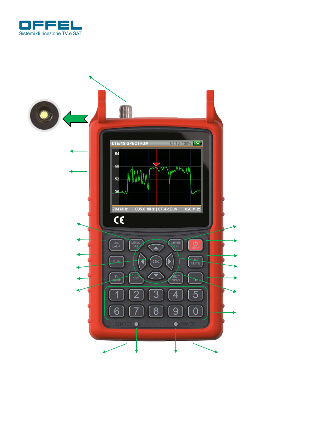
3. FUNCTIOS ................................................................................................................................................................................... 5
4. MAIN FEATURES ........................................................................................................................................................................ 6
5. TECHNICAL SPECIFICATIONS .................................................................................................................................................. 7
6. DVB-S/S2 ..................................................................................................................................................................................... 9
6.1 LEVEL MEASURES .............................................................................................................................................................. 9
6.2 SATELLITE SEARCH MENU .............................................................................................................................................. 10
6.3 SPECTRUM ANALYSIS MENU ........................................................................................................................................... 12
6.4 TRANSPONDER CONTROL MENU ................................................................................................................................... 13
6.5 CONSTELLATION MENU ................................................................................................................................................... 14
6.6 MULTI-LEVEL CONTROL MENU ....................................................................................................................................... 14
6.7 AUTOMATIC SEARCH MENU ............................................................................................................................................ 15
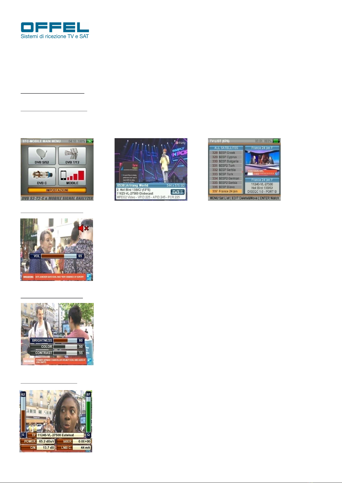
6.8 CHANNEL LIST MENU ........................................................................................................................................................ 15
6.9 SATELLITE SETTINGS MENU ........................................................................................................................................... 17
6.10 DVB-S/S2 SETTINGS ........................................................................................................................................................ 17
7. DVB-C ........................................................................................................................................................................................ 18
7.1 MENÙ MISURA LIVELLI ...................................................................................................................................................... 18
7.2 MENÙ ANALISI DELLO SPETTRO ...................................................................................................................................... 20
7.3 MENÙ COSTELLAZIONE .................................................................................................................................................... 21
7.4 MENÙ TILT/LIMIT ................................................................................................................................................................ 22
7.5 MENÙ TABELLA RICERCA ................................................................................................................................................. 22
7.6 LISTA CANALI...................................................................................................................................................................... 22
7.7 IMPOSTAZIONI CATV ......................................................................................................................................................... 23
7.8 PIANO FREQUENZE ........................................................................................................................................................... 23
8. DVB-T/T2 ................................................................................................................................................................................... 24
8.1 LEVEL MEASUREMENT MENU .......................................................................................................................................... 24
8.2 SPECTRUM ANALYSIS MENU ........................................................................................................................................... 26
8.3 CONSTELLATION MENU .................................................................................................................................................... 27
8.4 TILT / LIMIT MENU .............................................................................................................................................................. 28
8.5 SEARCH TABLE MENU ....................................................................................................................................................... 28
8.6 CHANNEL LIST .................................................................................................................................................................... 29
8.7 TERRESTERIAL TV SETTINGS ............................................................................................................................................ 29
8.8 TERRESTERIAL TV FREQUENCY PLAN ............................................................................................................................. 29
9. MOBILE MENU ......................................................................................................................................................................... 30
9.1 LTE/4G SPECTRUM - 800 MHz BAND ................................................................................................................................ 30
9.2 GSM900 SPECTRUM - 900 MHz BAND .............................................................................................................................. 31
9.3 DCS1800 SPECTRUM - 1800 MHz BAND ......................................................................................................................... 32
9.4 UMTS2100 SPECTRUM - 2100 MHz BAND ........................................................................................................................ 34
9.5 MOBILE SETTINGS ............................................................................................................................................................ 35
10 MAIN SETTINGS MENU OF THE DEVICE ............................................................................................................................... 36
SUPPORTED RESOLUTIONS ............................................................................................ Errore. Il segnalibro non è definito.
DECLARATION OF CONFORMITY ....................................................................................... Errore. Il segnalibro non è definito.

User manual
Art. 55-106 M101
Rev. 0 03.2019 pag. 3
Offel s.r.l. Via Lato di Mezzo, 32 48022 Lugo RA - Italy Tel. +39 0545/22542 [email protected] www.offel.it
WARNINGS
The information contained in this manual is provided subject to errors and modifications.
The warranty does not cover damage resulting from incorrect use of the information contained in this manual.
In case of tampering, the company OFFEL s.r.l. is not liable for any product malfunctions. Anyone who makes changes to a CE marked product that
lead to non-compliance is subject to the penalties provided for by art. 11 Legislative Decree 615/96.
LIABILITY DISCLAIMER. This document is based on information available at the time of its publication. Although every effort has been
made to ensure the accuracy of the content, the information contained in it is not intended to describe all the details or variations of the
software and / or hardware, nor cover any possible eventualities concerning use and maintenance. The manual can describe functions
that are not present in every software / hardware. The manufacturer assumes no obligation to notify holders of this document of
subsequent changes.
CHARACTERISTICS AND INFORMATION CONTAINED IN THIS MANUAL ARE SUBJECT TO CHANGE WITHOUT NOTICE.
WARRANTY. The warranty is limited to material and construction defects. This excludes:
- damage caused by accident, negligence, modification or improper use;
- damage caused by lightning, surges, liquids, fire, acts of war, vandalism, insufficient ventilation or other causes not attributable to the
manufacturer;
- damage caused by repairs carried out by unauthorized service centers / unauthorized persons and / or by the use of non-original spare parts.
These warranty conditions do not affect the rights provided in favor of the consumer according to the provisions of the Consumer Code
(Legislative Decree 206/2005) or other national legislative provisions
Q This product complies with EU directive 2002/96 / EC. The symbol of the crossed-out bin shown on the appliance indicates
that the product, at the end of its useful life, having to be treated separately from household waste, must be delivered to a
separate collection center for electrical and electronic equipment, or returned to the seller at the time of the purchase of a new
equivalent equipment. The user is responsible for providing the appliance at the end of its life with the appropriate collection
facilities. Adequate separate collection for the subsequent start-up of the appliance for recycling, treatment and
environmentally compatible disposal helps to avoid possible negative effects on the environment and on health and promotes
the recycling of the materials of which the product is composed. For more detailed information on the collection systems
available, contact your local waste disposal service.
1. SAFETY INSTRUCTIONS
For a correct use of the instrument, the safety instructions and the indications for use described in this manual must
be observed.
• Do not use the instrument for purposes other than those described in this manual.
• Use the battery charger supplied as standard to avoid any deterioration of the instrument and to protect its
measurement capabilities.
• Do not use the instrument in an explosive environment.
• Do not use the instrument in wet or high humidity environments. Neither liquids nor other substances must come into
contact with the inside of the meter.
• In the event of a sudden transition from a warm to a cold environment, do not use the instrument immediately. It is
advisable to switch off the instrument and switch it on again after 1 - 2 hours.
• Keep the instrument as clean as possible in clean and sufficiently ventilated areas.
• Do not cover the instrument and do not place it on sources of heat.
• Do not leave the instrument in environments with critical conditions (eg excessive heat, cold or humidity).
• Clean the shell with a soft cloth.
• Do not remove the cover. Only qualified personnel will be able to carry out any repairs or maintenance procedures
on the instrument. In this case, original spare parts must be used.
• Do not open the instrument: risk of electric shock.
ATTENTION: the instructions contained in this manual refer to the factory installed software version. In the event of
software updates, the interface may change without prior notice.

User manual
Art. 55-106 M101
Rev. 0 03.2019 pag. 4
Offel s.r.l. Via Lato di Mezzo, 32 48022 Lugo RA - Italy Tel. +39 0545/22542 [email protected] www.offel.it
2. CONTENT OF THE PACKAGE
The package includes the following items:
• Field measurement
• Silicone cover with shoulder strap and case
• 12V 1.5A power supply
• Car charger
• AV cable
• Female F connector and BNC connector
• Padded bag with shoulder strap
• User manual
Fig. 1: Silicone cover and case Fig. 2: power supply 220 Va.c. Fig. 3: Car charger
Fig. 4: AV cable Fig. 5: Female F connector and BNC connector Fig. 6: Padded bag with shoulder strap

User manual
Art. 55-106 M101
Rev. 0 03.2019 pag. 5
Offel s.r.l. Via Lato di Mezzo, 32 48022 Lugo RA - Italy Tel. +39 0545/22542 [email protected] www.offel.it
3. FUNCTIONS OVERVIEW
RF & LNB INPUT
TVCC INPUT
AV INPUT
12V INPUT CHARGE LED LED POWER USB INPUT
NUMERIC KEYPAD
EDIT - SPAN - FREQ
POINTER
FRECCE DIREZIONALI
MUTE - SAT LIST
ON - OFF
LEVEL - C/N - MOTOR
SAT MENU
SELECT
FLASHLIGHT ON/OFF
AV IN SELECTION
TV / RADIO SELECTION
EXIT
OK - ENTER
LED FLASHLIGHT

User manual
Art. 55-106 M101
Rev. 0 03.2019 pag. 6
Offel s.r.l. Via Lato di Mezzo, 32 48022 Lugo RA - Italy Tel. +39 0545/22542 [email protected] www.offel.it
4. MAIN FEATURES
• High resolution 3.5 inch LCD TFT screen
• Measurement of DVB-S / S2 / T / T2 / C signals
• Unique RF input (45 ÷ 2150 MHz) at 75 Ω with F connector
• Input video signals AHD and CVBS for CCTV
• MPEG2 and MPEG4, SD and HD images with program list, Audio and Video PIDs all on screen
• Measure levels in dBm, dBuV and dBmV
• Voltage level test for end user
• AAC and DOLBY audio support
• Programmable frequency plans (30 CATV plans, 30 Terrestrial TV plans, 150 SAT plans)
• 5000 storable frequencies
• Automatic scanning and preparation of terrestrial and CATV signals frequency table
• 800 MHz processor speed - 8MB memory
• Backlit silicone keyboard
• Timer function for battery saving
• Integrated microphone
• Sound alarms
• LED flashlight
• Replaceable 7.4V / 3000mAh lithium batteries, lasting> 4h
• 0.6 kg in weight with batteries
• Dimensions: 190 x 110 x 60 mm
• Working temperature 0 ° C to +50 ° C
• Humidity up to 90% without condensation
• Software upgradeable via USB
• Compact and portable

User manual
Art. 55-106 M101
Rev. 0 03.2019 pag. 7
Offel s.r.l. Via Lato di Mezzo, 32 48022 Lugo RA - Italy Tel. +39 0545/22542 [email protected] www.offel.it
5. TECHNICAL SPECIFICATIONS
TERRESTRIAL SIGNALS
Measured standards DVB-T/T2 and analog signal level measurements
Input frequencies 45 ÷ 1002 MHz
Input signal level -90 ÷ 0 dBm
Antenna power supply 5V / 12V / 20V, IMax 250 mA
Constellation QPSK, 16QAM, 64QAM (DVB-T), 256QAM (DVB-T2)
FEC DVB-T: 1/2, 2/3, 3/4, 5/6, 7/8 - DVB-T2: 1/2, 2/3, 3/4, 5/6, 7/8, 3/5, 4/5
Channels bandwidth 1.7 MHz, 5MHz, 6 MHz, 7 MHz, 8 MHz
Digital signal quality measurements MER - BER - C/N
Measurement accuracy level 1 dB typ. (2.5 dB max.)
Spectrum analyzer Real time
Span of the spectrum 15, 30, 50, 100, 200, 500, 1000 MHz
Transponder identification Automatic, NIT function in the Spectrum menu
TILT / LIMIT function For the whole band
Analog V / A ratio 4 ÷ 26 dB
Analog audio 4,5 MHz, 5,5 MHz, 6,0 MHz, 6,5 MHz
SATELLITE SIGNALS
Measured standards DVB-S/S2
Input frequencies 950 ÷ 2150 MHz
Input signal level -80 ÷ 0 dBm
band switching control 22 KHz
Power supply LNB 13V / 18V / 21 V, IMax 500 mA
Constellation QPSK, 8PSK
FEC DVB-S: 1/2, 2/3, 3/4, 5/6, 7/8 - DVB-S2: 1/2, 2/3, 3/4, 5/6, 8/9, 9/10, 2/5, 3/5
Symbol Rate 1 ÷ 45 Mbps – automatic selection
Signal quality measures MER - BER - C/N
Measurement accuracy level 1 dB typ. (2.5 dB max.)
Real-time spectrum analyzer Real time
Span of the spectrum 50, 75, 150, 300, 600, 1200 MHz
Transponder identification Automatic, NIT function in the Spectrum menu
Transponder control 4 tp levels of one or two satellites in a screen
Multi-level control 2 LNB Dual Feed sat levels in one screen
Auto Port Scan Diseqc 1.0 -1.1 - Unicable ports for each satelitte
DiSEqC supported DiSEqC 1.x, DiSEqC 2.x and USALS
Unicable supported Unicable 1 and 2 (EN50494/EN50607)
Types of LNBs supported no. 32

User manual
Art. 55-106 M101
Rev. 0 03.2019 pag. 8
Offel s.r.l. Via Lato di Mezzo, 32 48022 Lugo RA - Italy Tel. +39 0545/22542 [email protected] www.offel.it
CATV SIGNALS
Measured standards DVB-C and analog CATV measurements
V/A ratio 4 ÷ 26 dB
Input frequencies 45 ÷ 1002 MHz
Input signal level -90 ÷ 0 dBm
Constellation 16QAM, 32QAM, 64QAM, 128QAM, 256QAM
Channel bandwidth 6 MHz, 7 MHz, 8 MHz
Digital signal quality measurements MER - BER - C/N
Measurement accuracy level 1 dB typ. (2.5 dB max.)
Real-time spectrum analyzer Real time
Span of the spectrum 15, 30, 50, 100, 200, 500, 1000 MHz
Transponder identification Automatic, NIT function in the Spectrum menu
TILT / LIMIT function for the whole band
Analog audio 4,5MHz, 5,5 MHz, 6,0 MHz, 6,5 MHz
Symbol Rate 2 ÷ 6.999 Mbps - automatic selection
MOBILE PHONE SIGNALS
LTE / 4G 800MHz
GSM900 900MHz
DCS1800 1800MHz
UMTS2100 2100MHz
Power measurement interval -80 ÷ 10 dBm
POWER SUPPLY
Lithium battery 7.4V / 3000 mAh
Supply voltage 12Vd.c. 1,5A
Ingresso: 100 ÷ 240 Va.c. 50/60 Hz
PHYSICAL CHARACTERISTICS
Dimensions (W x L x H) 110 x 190 x 60 mm
Net weight 0,6 Kg with batteries

User manual
Art. 55-106 M101
Rev. 0 03.2019 pag. 9
Offel s.r.l. Via Lato di Mezzo, 32 48022 Lugo RA - Italy Tel. +39 0545/22542 [email protected] www.offel.it
6. DVB-S/S2
After turning the instrument on using the ON / OFF switch and connecting the signal cable to be measured to
the corresponding input, press the MENU button to display the main menu.
6.1 LEVEL MEASURES
STARTING THE DEVICE:
To access the satellite menu, in the main menu choose DVB S / S2 (fig. 8).
Pressing the ENTER key, the TV / radio channel list will appear on the TV transmission screen (fig. 10).
Fig. 8 Fig. 9 Fig. 10
SOUND ADJUSTMENT:
While watching a channel, you can change the audio volume with the RIGHT / LEFT
buttons or mute it with the MUTE button (fig. 11).
Fig. 11
COLOR ADJUSTMENT:
While watching a channel, you can change the image color settings by holding down
the EDIT button (fig. 12).
Fig. 12
LEVEL INDICATORS:
While watching a channel, you can view the channel signal levels in real time on the
screen by pressing the LEVEL button (fig. 13). The color of the level indicators will
change from gray to green and red when attaching any channel.
Fig. 13

User manual
Art. 55-106 M101
Rev. 0 03.2019 pag. 10
Offel s.r.l. Via Lato di Mezzo, 32 48022 Lugo RA - Italy Tel. +39 0545/22542 [email protected] www.offel.it
6.2 SATELLITE SEARCH MENU
By pressing the MENU button you can display the main menu on the screen.
Using the UP / DOWN buttons select the SATELLITE SEARCH menu (fig. 14).
Select the satellite you want to set or you want to see the signal levels, the transponder, the DiSEqC type and the type
of LNB and press ENTER (fig. 15).
Fig. 14 Fig. 15 Fig. 16
It is thus possible to see the signal levels appear on the screen and check whether their values are more or less high
(fig. 16). By pressing the LEVEL button it is possible to see the levels on the screen in detail (fig. 17).
Fig. 17
With the RIGHT / LEFT buttons it is possible to review the various transponders.
After adjusting the signal level in the best way, you can press the ENTER button and perform a CHANNEL SCAN.
Scanning can be performed in SINGLE TP mode (fig. 18), ALL TP (fig. 19) and BLIND SCAN (fig. 20).
The detected channels can be added to the channel list by following the instructions shown in the figures below (fig.
21-23).
After that, the channels are stored in the memory and added to the end of the channel list.
Fig. 18 Fig. 19 Fig. 20
Fig. 21 Fig. 22 Fig. 23

User manual
Art. 55-106 M101
Rev. 0 03.2019 pag. 11
Offel s.r.l. Via Lato di Mezzo, 32 48022 Lugo RA - Italy Tel. +39 0545/22542 [email protected] www.offel.it
USALS (Universal Satellites Automatic Location System) - MOTOR SETTINGS:
To use DiSEqC Motors commands with the USALS system, on the SATELLITE SEARCH screen in the DiSEqC section
select USALS MOTOR (fig. 24). Keeping the EDIT button pressed for 2-3 seconds, the USER POSITION screen
appears (fig. 25). Enter the coordinates of the area where the installation will be performed, set the desired satellite
and confirm with the OK box; moving to GO and pressing the ENTER key the dish will automatically go into position.
Fig. 24 Fig. 25
SETTINGS MENU UNICABLE I & II:
You can use this menu for multiswitches or unicable LNBs (dCSS or SCR) and run the tests after changing the following
settings (fig. 26-31). First select UNICABLE (fig. 26) or UNICABLE II (fig. 27) in the DiSEqC section, go to the DOOR
section and keep the EDIT button pressed for 2-3 seconds (fig. 28).
Fig. 26 Fig. 27 Fig. 28
In the EDITOR UNICABLE screen it is possible to adjust the IF output frequencies based on the Unicable Multiswitch
or Unicable SCR LNB type that will be tested. Then you can test the signals from the SATELLITE SETTINGS menu.
Fig. 29 Fig. 30 Fig. 31
DISEQC 1.2 - MOTOR SETUP MENU:
Fig. 32 Fig. 33
I
n the DiSEqC section select the Diseqc
1.2 Motor option and press the ENTER
button to see the signal levels in the
SATELLITE SETTINGS menu. Here you
can see the signal levels and at the same
time manually rotate the DiSEqC 1.2
Motor in the EAST /
WEST directions
with the RIGHT / LEFT keys.
During these operations the instrument's
battery could be discharged more quickly
since it consumes more than the normal
use of the instrument. It is therefore
advisable to keep the power supply
handy during this type of scan.

User manual
Art. 55-106 M101
Rev. 0 03.2019 pag. 12
Offel s.r.l. Via Lato di Mezzo, 32 48022 Lugo RA - Italy Tel. +39 0545/22542 [email protected] www.offel.it
6.3 SPECTRUM ANALYSIS MENU
Press the MENU button and select SPECTRUM in the main menu (fig. 34).
After setting the Satellite, LNB, Power and DiSEqC sections, select the desired IF frequency in the TP section and
press the ENTER button (fig. 35). The spectrum of signals will appear (fig. 36).
Fig. 34 Fig. 35 Fig. 36
Pressing once on the LEVEL button, the C / N value will appear on this screen (fig. 37).
Fig. 37
When you press the MENU button on the spectrum screen (fig. 38) with the MASK SAVE function you can store the
spectrum mask and with the MASK LOAD function you can then recall it later from the memory during a new installation
that needs the same settings.
Fig. 38 Fig. 39
Thanks to the AUTO RANGE mode it is possible to adapt the upper and lower signal levels of the screen to the
automatic measurement levels. Thanks to the FULL / EMPTY function: you can see the levels in the spectrum screen
as full or empty (fig. 39). By pressing the EDIT button it is possible to modify the IF Frequency, Span, Reference,
Gamma, Power and Mode values (fig. 40). With the MODE option it is possible to modify the spectrum speed
(NORMAL or FAST): when it is in NORMAL mode the spectrum will move at the optimal speed. When the FAST mode
is selected the spectrum will move faster (in this case the image may not be displayed in detail).
Fig. 40

User manual
Art. 55-106 M101
Rev. 0 03.2019 pag. 13
Offel s.r.l. Via Lato di Mezzo, 32 48022 Lugo RA - Italy Tel. +39 0545/22542 [email protected] www.offel.it
NIT RECOGNITION:
By moving the IF frequency slider to a signal in the SPECTRUM menu, it is possible to automatically find the channel
list and the Satellite position in Uplink by pressing the ENTER button (fig. 41).
Fig. 41 Fig. 42
NOTE: the name of the satellite may be incorrect due to the information contained in the NIT data supplied by the
transmission company. This can also occur when the transmission company transmits to 2-3 satellites simultaneously.
Fig. 43 Fig. 44
By pressing CHANNEL LIST (fig. 42) it is possible to display the channel lists (fig. 43) and with the SAVE CHANNELS
function (fig. 44) record the channels in the memory with the universal LNB set.
6.4 TRANSPONDER CONTROL MENU
Fig. 45
Press the MENU button and select TP CONTROL from the main menu.
This menu also allows you to check the signal levels of multiple frequencies
simultaneously.
CONTROL OF A SINGLE SATELLITE:
Fig. 46 Fig. 47
In the TYPE section select SINGLE and
press ENTER after having set the
necessary settings (Satellıte, DiSEqC,
Door).
As shown in fig. 47, it is possible to
display the signal levels of 4 different
frequencies of a single satellite on the
same screen. In this way it is possible to
check if the signal levels and the satellite
dish setting are correct at all frequencies
or not.

User manual
Art. 55-106 M101
Rev. 0 03.2019 pag. 14
Offel s.r.l. Via Lato di Mezzo, 32 48022 Lugo RA - Italy Tel. +39 0545/22542 [email protected] www.offel.it
CONTROL OF TWO SATELLITES:
In the TYPE section select DOUBLE and press ENTER after having set the necessary settings (fig. 48).
Fig. 48 Fig. 49 Fig. 50
As shown in fig. 49-50 it is possible to display on the same screen the signal levels of 8 different frequencies from 2
different satellites. It is possible to test and check the correctness of the multiswitch and the assembly of the system
by displaying all the frequencies on the same screen.
6.5 CONSTELLATION MENU
Press the ENTER button and select CONSTELLATION in the main menu (fig. 51). The constellation menu shows in a
graph the correctness of the digital I / Q symbol coordinates received at any time. In this way it is also possible to
check the correctness of the modulation (QPSK, 8PSK).
Fig. 51 Fig. 52 Fig. 53
Enter the CONSTELLATION menu, select the satellite and the frequency of the transponder whose correctness is to
be checked and press the ENTER button after setting all the settings. The constellation diagram shows the 4 QPSK
signals (fig. 52) or the 8 8PSK signals (fig. 53). The closer the coordination points are to each other, the more the
signal is correct.
6.6 MULTI-LEVEL CONTROL MENU
Press the MENU button and select MULTI-LEVEL CONTROL in the main menu (fig. 54).
Fig. 54 Fig. 55 Fig. 56
In the multi-level control menu, the signal levels of each frequency from 2 different satellites are shown on the screen
(fig. 56). In this way, monoblock LNB installations and multiswitch tests can easily be performed.

User manual
Art. 55-106 M101
Rev. 0 03.2019 pag. 15
Offel s.r.l. Via Lato di Mezzo, 32 48022 Lugo RA - Italy Tel. +39 0545/22542 [email protected] www.offel.it
6.7 AUTOMATIC SEARCH MENU
Press the MENU button and select AUTOMATIC SEARCH in the main menu (fig. 57). In this menu it is possible to
see which satellite is connected to which DiSEqC port.
Fig. 57 Fig. 58
Select NONE / NA in cases where the DiSEqC switch is not available and the cable is directly connected to the LNB
(fig. 58).
Examples of searches for the DiSEqC port are shown below (fig. 59 Tone Burst and fig. 60 DiSEqC 1.0).
Fig. 59 Fig. 60
6.8 CHANNEL LIST MENU
While watching a channel, you can call up the CHANNEL LIST by pressing the ENTER button in the main menu (fig.
61).
Fig. 61
It is possible to select, cancel and reposition in the CHANNEL LIST menu the TV and Radio channels one by one or
based on the name of the satellite (fig. 62).
Fig. 62

User manual
Art. 55-106 M101
Rev. 0 03.2019 pag. 16
Offel s.r.l. Via Lato di Mezzo, 32 48022 Lugo RA - Italy Tel. +39 0545/22542 [email protected] www.offel.it
ORDERING VIA SATELLITE:
After entering the CHANNEL LIST menu, press the MENU button and select the satellite (fig. 63). In this case only the
channels of the selected satellite will be displayed.
Fig. 63
DELETE CHANNELS:
In the CHANNEL LIST menu, press the EDIT button and select DELETE (fig. 64).
Fig. 64 Fig. 65
Select the channels you want to delete on the screen one by one with the ENTER key (fig. 65) and finally press EDIT.
The channels will be permanently deleted when DELETE is selected in the EDIT menu.
MOVE THE CHANNELS:
In the CHANNEL LIST menu, press the EDIT button and select MOVE (fig. 67).
Fig. 66 Fig. 67
Select the channels you want to move with the ENTER key one by one and press the EDIT button when you are in the
position where you want to transfer them. The channels will then be transferred to the desired position (fig. 68).
Fig. 68

User manual
Art. 55-106 M101
Rev. 0 03.2019 pag. 17
Offel s.r.l. Via Lato di Mezzo, 32 48022 Lugo RA - Italy Tel. +39 0545/22542 [email protected] www.offel.it
6.9 SATELLITE SETTINGS MENU
Press the MENU button and select SATELLITE SETTINGS in the main menu (fig. 69).
In this menu it is possible to choose the DiSEqC and LNB types suitable for the satellites and transponders in the area
in which the services are provided (fig. 70). The settings will take effect in all menus and this will allow you to work
faster. Please always check the correctness of the settings.
Fig. 69 Fig. 70 Fig. 71
In addition to this, it is possible to delete ALL the satellite TRANSPONDERS (fig. 71) and perform a CHANNEL SCAN
for these satellites (fig. 74).
Fig. 72 Fig. 73 Fig. 74
6.10 DVB-S/S2 SETTINGS
Through the DVB-S / S2 SETTINGS menu (fig. 75) it is possible to make changes in the DVB-S/S2 menus.
Fig. 75 Fig. 76 Fig. 77
On the SETTINGS screen (fig. 76) you can set the following options:
DISPLAY: shows the power level indicators in dBm, dBuV or dBmV.
CALIBRATION: you can calibrate the level if you think the signal measurement indicator is low or high.
AUTO LOOP: it is possible to select in the SATELLITE and AUTOMATIC SEARCH menu the number of satellites you
want to control.
ACTIVE REGION: it is possible to modify the active region for the list of received satellites.
MEMORY INFO: you can check the amount of memory used in the satellite section, delete all the transponders and
all the channels and restore the factory settings (fig. 77).

User manual
Art. 55-106 M101
Rev. 0 03.2019 pag. 18
Offel s.r.l. Via Lato di Mezzo, 32 48022 Lugo RA - Italy Tel. +39 0545/22542 [email protected] www.offel.it
7. DVB-C
STARTING THE DEVICE:
Press the POWER ON / OFF button and turn on the device.
In the main menu select DVB-C (fig. 78); the TV / Radio channel list will appear on the screen.
Fig. 78 Fig. 79 Fig. 80
LEVEL INDICATORS:
Fig. 81 Fig. 82
While watching a channel, you can
instantly view the channel signal levels
watched on the screen in real time by
pressing the LEVEL button (fig. 81-82).
7.1 LEVEL MEASURE MENU
Press the MENU button to enter the CATV MENU screen (fig. 83). To start taking
measurements, select LEVEL MEASUREMENT. In the selected frequency plan it is
possible to perform both ANALOGUE and DVB-C / QAM DIGITAL measurements.
Fig. 83
DVB-C / QAM:
In the CATV LEVEL MEASUREMENT menu, under the item SYSTEM select DVB-C and press ENTER.
Use the RIGHT / LEFT buttons to select the CHANNEL you want to measure, or go to FREQUENCY and enter the
desired frequency and select a bandwidth of 6, 7 or 8 MHz (fig. 84).
Fig. 84 Fig. 85 Fig. 86
After entering the parameters of the frequency you want to measure, press the ENTER button to enter the
measurement screen (fig. 85-86).
The thick orange bar on the right of the screen visually indicates the signal level.

User manual
Art. 55-106 M101
Rev. 0 03.2019 pag. 19
Offel s.r.l. Via Lato di Mezzo, 32 48022 Lugo RA - Italy Tel. +39 0545/22542 [email protected] www.offel.it
The signal level is indicated in figures below the orange bar.
The green area indicates whether the level performance bar is within the Max and Min values that can be selected in
the settings menu.
On the left side of the screen it is possible to see the frequency parameters and signal quality measurement values
such as MODULATION, BER and MER.
An ERROR indication will appear in the small box at the bottom right when the signal values are insufficient (fig. 85)
and an OK indication when the signal values are appropriate (fig. 86).
When the signal levels are correct, the channel names will be indicated in the orange bar.
By pressing the LIST button you can see the channel names in the measured frequency.
Note: it is possible to quickly switch to the other menus related to the measured signal by selecting one of the following
items: SHIFT, CONSTELLATION or SEARCH on the lower side of the screen.
SEARCH FOR A CHANNEL AND REGISTER IN THE CHANNEL LIST:
Select the SEARCH item at the bottom of the screen, on the right (fig. 87).
Fig. 87 Fig. 88 Fig. 89
Fig. 90 Fig. 91
In the CHANNEL SCAN screen it is
possible to perform a scan by selecting
the NON-ENCODED, CODIFIED or both
together items from the CHANNELS item
and pressing ENTER next to START (fig.
88).
When the scan is finished, an information
screen will appear on the channels found
and you will be asked if you want the
channels to be recorded or not (fig. 91).
DVB-C ANALOGUE MEASUREMENT:
In the CATV LEVEL MEASUREMENT menu, under SYSTEM select ANALOGUE (fig. 92).
Use the RIGHT / LEFT buttons to select the CHANNEL and the FREQUENCY you want to measure.
It is possible to enter information on the video frequency and audio frequency for ANALOGUE measurement with the
EDIT button, moving over the boxes.
Fig. 92 Fig. 93 Fig. 94
To go to the measurement screen, press the ENTER button after entering the parameters of the frequency you want
to measure. In this screen it is possible to view the channel name, the frequency and power of the video carrier and
the audio carrier and the V / A (video / audio) ratio measured in dB (fig. 93-94).

User manual
Art. 55-106 M101
Rev. 0 03.2019 pag. 20
Offel s.r.l. Via Lato di Mezzo, 32 48022 Lugo RA - Italy Tel. +39 0545/22542 [email protected] www.offel.it
The green area indicates whether the orange video level bar and the blue audio level bar are within the maximum and
minimum values selected in the settings menu.
An ERROR indication will appear in the small box at the bottom right when the signal values are insufficient and an
OK indication when the signal values are correct.
Note: it is possible to quickly switch to the other menus related to the measured signal by selecting the item SHIFT,
CONSTELLATION or SEARCH at the bottom of the screen.
7.2 SPECTRUM ANALYSIS MENU
Press the MENU button to enter the CATV MENU screen. To start measuring, select SPECTRUM (fig. 95). The device
will display all the ANALOG and DIGITAL signals within the span (frequency range) when it is set to the SPECTRUM
measurement mode.
Fig. 95 Fig. 96 Fig. 97
Select the ANALOGUE or DIGITAL system, the WIDTH (SPAN), the REFERENCE (upper measurement point) and
the RANGE (the interval between the upper and lower measurement points) and press ENTER (fig. 97).
Fig. 98 Fig. 99 Fig. 100
The ANALOG and DIGITAL signals can be displayed in different forms on the spectrum screen depending on the
bandwidth and power levels (fig. 98-100).
By clicking on the MENU button:
When in the Spectrum screen click on the MENU button, the screen of fig.101 appears.
Fig. 101
AUTO RANGE: determines the highest and lowest values of the signal level
and establishes the interval of the screen indicator according to this.
FULL / EMPTY: shows the image of the empty or full spectrum.
MASK SAVE: records the image of the spectrum on the screen, to be able to
recall it later and compare it with the last measurement performed.
SAVE TO USB: make
s it possible to record the image data of the spectrum on
the monitor on the USB memory card.
Table of contents
Other Offel Measuring Instrument manuals
Popular Measuring Instrument manuals by other brands

Taxitronic
Taxitronic TX52 installation manual

Bently Nevada
Bently Nevada 3300/70 Operation manual

Gossen MetraWatt
Gossen MetraWatt METRAport 40S operating instructions

Kathrein
Kathrein MSK 125 operating manual

Northern Design
Northern Design MultiCube Series Connection guide

Sony
Sony Handycam HDR-HC9 Service manual