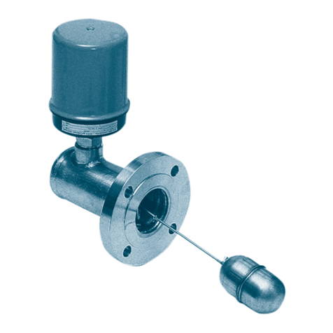
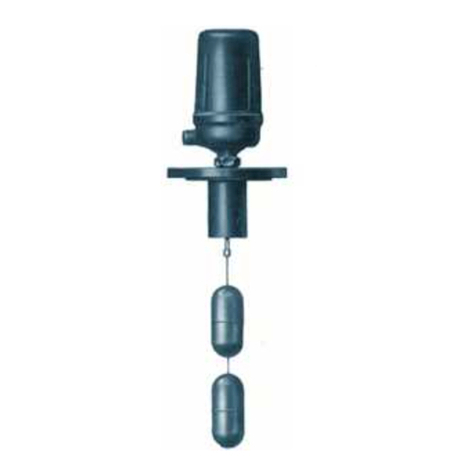
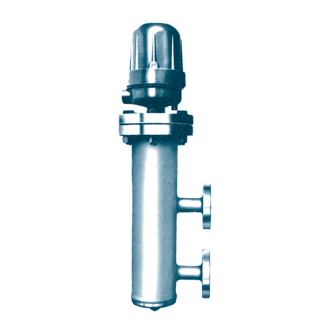
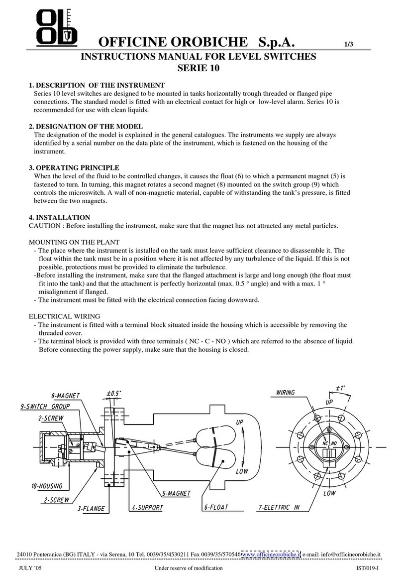
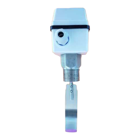
OFFICINE OROBICHE PL Series User manual

OFFICINE OROBICHE S.p.A.
1/7
INSTRUCTION MANUAL FOR FLOW SWITCHES
PL SERIES
24010 Ponteranica (Bergamo) ITALY - via Serena, 10 - Tel. 0039/035/4530211 - Fax 0039/035/570546 - www.officineorobiche.it-e-mail:info@officineorobiche.it
*****************************************************************************************************************************************************************
JULY ’14 Information subject to change without prior notice IST/158-I
1.INSTRUMENT DESCRIPTION
Flow switches PL series are designed to be mounted in an upright position along horizontal pipes.
These models are equipped with a tripping device, which can be equipped with single (SPDT) or double (DPDT) exchange
contacts for high or low flow rate control and/or alarms.
2. MODEL IDENTIFICATION
11 12 13 14 15 16 17 18 19 20
PL . . . . . . .
PNA
Aluminium
xx
Special
version
Finning R3Ø R1 R4
Body material
SPDT
Ø 2
Contact type
PneumaticWater-proof
HG Bulb
A I J
Internal material/Paddle
VD
AISI 3162
M6
Water-proof
Golde- Contacts
Base Current
Ermet.Sealed
with inert gas
Model
Water-proof
M4
EPWP Ex-d
Case
M14
316
Direct
M2 M3
Acc 304
Contact
DPDT

OFFICINE OROBICHE S.p.A.
2/7
24010 Ponteranica (Bergamo) ITALY - via Serena, 10 - Tel. 0039/035/4530211 - Fax 0039/035/570546 - www.officineorobiche.it-e-mail:info@officineorobiche.it
*****************************************************************************************************************************************************************
JULY ’14 Information subject to change without prior notice IST/158-I
3. OPERATING PRINCIPLE
To the paddle(1), which is soaked in the fluid, through a rod, a
small piston (2) made from magnetic stainless steel is
connected; this small piston is housed in a pit (3) made from
non-magnetic material.
On the pit (3) a tripping device, which is drawn schematically
beside, is mounted. It is composed of a magnet (4) and a
miniature switch (5) that are connected to one another by
means of levers.
In low flow-rate conditions (fig.“A”), the magnet (4) is at rest,
whereas in high flow-rate conditions (fig.“B”), the magnet (4)
is attracted by the small piston (2) that causes the miniature
switch (5) to operate.
The difference between high and low flow-rate is called
”tripping differential”.
The arrow indicates the direction fo the flow.
4. INSTALLATION
4.1 INSTALLATION ON THE SYSTEM
Before installation, check the line connections for compatibility with the instrument connections.
The flow switch shall be installed in a perfectly upright position and the piping shall be straightaway for at least 5D
upstream and 3D downstream.
The flow switch body has an arrow indicating the direction
taken by the flow; comply with such indication at the assembling
stage.
Remove the adhesive tape that locks the paddle and the plastic
strip inserted in the tube, so that the stem becomes free to move.
Ensure that the entire paddle is inside the piping and that, at rest
(no fluid), it does not touch the bottom of the piping.
It is strictly prohibited to load the instrument with external loads
and it is the user’s duty to protect it from strain; do not use it as
resting point.
To avoid effects of galvanic corrosion, any use of materials
featuring a different electrochemical potential is prohibited. The
user shall adopt all those technical devices that can prevent this
event from occurring.
The system shall be equipped with the specified technical
device, to make up for overpressure going beyond the
maximum envisaged point.
For installation on piping exposed to strong vibration,
please contact the Customer service department.
4.2 WIRING
The flow switch has a terminal board inside the case for NC - C - NO connections (see
figure on the right).
Make sure that the cover of the housing is closed properly before powering up.
The user shall provide suitable ground connections that are such as to protect the staff and
any other equipment possibly present.
The NC-NO condition referred to herein is with null fluid.
NO =NORMALLY OPEN
C = COMMON
NC =NORMALLY CLOSED

OFFICINE OROBICHE S.p.A.
3/7
24010 Ponteranica (Bergamo) ITALY - via Serena, 10 - Tel. 0039/035/4530211 - Fax 0039/035/570546 - www.officineorobiche.it-e-mail:info@officineorobiche.it
*****************************************************************************************************************************************************************
JULY ’14 Information subject to change without prior notice IST/158-I
5. SETTING AT WORK
Make sure that the use of the instrument does not exceed the intended conditions of use (higher temperature and
pressure values, lower flow rates) and that the applied electrical rating value complies with the rating plate values.
Verify that the instrument operates a correct switchover, by making the fluid flow rate vary a few times.
6. CALIBRATION
The unit is not generally factory-set, hence it demands on-site setting.
(See maintenance, operation point setting paragraphs).
7.MAINTENANCE
We recommend inspecting the flow switch on a routine basis (every 6 months or so) to guarantee full efficiency.
All maintenance activities shall be performed when the instrument is off, not under pressure and emptied of its fluid, at
room temperature (in the event of instruments working at high or low temperature) and free from the contact’s feeding
voltage.
7.1 WARNINGS
- NEVER open the cover of the case before the power supply has been cut off;
- NEVER leave the case without its cover for more than the time absolutely necessary for the inspection;
- NEVER use the flow switch with pressure or temperature levels in excess of those indicated on the ratings plate;
- NEVER use the flow switch with mains voltage in excess of that indicated on the ratings plate;
- NEVER adjust or replace any components without having first read the relevant instructions carefully. If in doubt,
contact our Customer Services;
- NEVER lubrificate instrument components;
-If being used with high temperatures, adopt all the relevant precautions to guarantee that service personnel are
protected during maintenance operations.
7.2 PADDLE ROUTINE INSPECTION
Ensure the device is disconnected from the system and with all the fluid already drained out.
-Disconnect the voltage supply;
-Dismount the device from the piping by lifting the upper flange of the body or by unscrewing the union
(take care not to spoil or damage the rod and paddle);
- Inspect the piping and check it is clean from incrustation and/or deposit (if any such deposits are found, perform a
thorough cleaning);
-Dismount the rod assembly by removing the pin that connects the fork to the paddle and the latter to the stud bolt;
- Inspect the pit inside making sure it is free from incrustation (clean with care if necessary);
-Ensure the paddle and the rod are free from incrustation (if any are found, clean thoroughly) and do not show any
marks of wear or corrosion (if necessary, replace them);
-Place the rod assembly and the paddle back in place carefully;
-Manually lift and lower the paddle to ensure the whole set slides freely;
-Ensure the switching unit trips when the paddle is in the high flow-rate position.
7.3 REPLACING THE PADDLE
After dismounting the old paddle (see par.7.2), fit the new one and perform all the checks as detailed in par. 7.2.
7.4 ROUTINE INSPECTION OF THE CONTACTS
Cut off the power supply.
Open the cover and visually check that the tripping unit is not damaged or worn. Manually move the magnet and check
that the micro-switch trips properly.

OFFICINE OROBICHE S.p.A.
4/7
24010 Ponteranica (Bergamo) ITALY - via Serena, 10 - Tel. 0039/035/4530211 - Fax 0039/035/570546 - www.officineorobiche.it-e-mail:info@officineorobiche.it
*****************************************************************************************************************************************************************
JULY ’14 Information subject to change without prior notice IST/158-I
7.5 REPLACING THE UNIT AND/OR MICRO-SWITCH
a - use a gauge to measure the position of the switch unit;
b - disconnect the wires from the terminal board (make a note
of the original connections) and remove the switch unit by
loosening the screw (2);
c -replace the micro-switch (1);
d -return the switch unit in the pit (3) in exactly the same
position as before;
e-adjust the tripping position by manually moving the magnet
(4) against the pit (3), tighten grub screw (5) until the
micro-switch trips and allow for one extra turn before
locking the grub screw;
f - check that the micro-switch (1) works efficiently using an
ohmmeter and a few manual tripping checks;
g - reconnect the wires to the terminal board as per point b.
7.6 SETTING THE OPERATION POINT
-The switching unit is factoryt-set to the minimum operation value.
-To set the operation point to the desired flow rate value, take the following steps:
a –place the switching unit on the top of the pit (3) by loosening screw (2);
b –adjust the fluid to the desired flow rate;
c –slowly lower the switching unit until the switching takes place (from pos. “A” to pos. “B”);
If the requested alarm is a high flow-rate one, you can lock the switching unit, if it is a low flow-rate one, slowly lift
the switching unit until the magnet (4) returns to pos. “A” and lock it in this position by means of screw (2).
8. DIMENSIONAL DRAWINGS OF THE BODY
RESET point :+25% from the Set
Dimensional values demanded in the order:
B= Pipe
C= Connections
PL11
PL12
PL13
SET m/s
(Low flow)
MODELLO
MODEL ØB
MIN.
6" sch.40
PL14
PL15
PL16
PL17
PL18
PL19
PL20
4" sch.40
4" sch.40
4" sch.40
3" sch.40
6" sch.40
4" sch.40
3" sch.40
4" sch.40
6" sch.40
WATER
WATER
AIR
0.7 - 1.4
1.2 - 2.4
4.5 - 8.0
0.1 - 0.6
0.4 - 0.9
0.4 - 1.0
1.1 - 2.7 WATER
WATER
AIR
WATER
4.0 - 7.0
0.3 - 0.7
0.4 - 0.9 WATER
FLUIDO
FLUID
WATER
WATER

OFFICINE OROBICHE S.p.A.
5/7
24010 Ponteranica (Bergamo) ITALY - via Serena, 10 - Tel. 0039/035/4530211 - Fax 0039/035/570546 - www.officineorobiche.it-e-mail:info@officineorobiche.it
*****************************************************************************************************************************************************************
JULY ’14 Information subject to change without prior notice IST/158-I
9. DRAWINGS OF CASE WITH DIMENSIONS
CODE LIQUID
TEMPERATURE ELECTRICAL CONNECTIONS ∅A
∅-10÷+135 EP WP
R3 -11÷-80 1/2” NPT 1/2” NPT
R1 +136÷+250 3/4” NPT 3/4” NPT
R4 +251÷+400 1/2” UNI 6125 1/2” (GAS) ISO 228/1
3/4” UNI 6125 3/4” (GAS) ISO 228/1
ISO M20 x 1.5 1/2” UNI 6125
ISO M20 x 1.5
EP CASE (EEx-d IIC T6)

OFFICINE OROBICHE S.p.A.
6/7
24010 Ponteranica (Bergamo) ITALY - via Serena, 10 - Tel. 0039/035/4530211 - Fax 0039/035/570546 - www.officineorobiche.it-e-mail:info@officineorobiche.it
*****************************************************************************************************************************************************************
JULY ’14 Information subject to change without prior notice IST/158-I
WP CASE (WATER PROOF IP 66)
10. RECOMMENDED SPARE PARTS (*)
When ordering spare parts, always indicate the instrument’s serial number.
You can find it on the ratings plate on the case (see Pos.9) and has 5 digits preceded by the letter “F” (e.g.: F45678).

OFFICINE OROBICHE S.p.A.
7/7
24010 Ponteranica (Bergamo) ITALY - via Serena, 10 - Tel. 0039/035/4530211 - Fax 0039/035/570546 - www.officineorobiche.it-e-mail:info@officineorobiche.it
*****************************************************************************************************************************************************************
JULY ’14 Information subject to change without prior notice IST/158-I
11. TROUBLESHOOTING
Flow switches of the PL series are not normally subject to faults.
In cases when the flow switch does not operate the switching, plase carry out a test procedure as per
paragraph 7. MAINTENANCE.
12. DISPOSAL
Once the flow switches have reached the end of their working life, they should be sent for disposal in accordance with
prevailing regulations.
During their disposal, pay special attention to the polymers, resins and rubber used in their construction (PVC, PTFE, PP,
PVDF, neoprene, viton etc.).
Metal components may be recycled after removing the gaskets, special coverings as requested by the customer or other
plastic materials.
WARNING:
If mercury bulb micro-switches (code VD) have been installed, they must be disposed of in accordance with prevailing
regulations concerning toxic substances; the other types of micro-switch are not subjected to these regulations.
13. WARRANTY
All series PL Flow switches are guaranteed against manufacturer defects for a period of 12 months from the date of
shipment.
In the event of a malfunction, if the defective part is returned within the above-mentioned warranty period, Officine
Orobiche undertakes to replace any damaged parts under warranty (excluding transport costs), provided that the defect is
not the result of the improper use of the instrument.
Officine Orobiche may not be held liable for any improper use of its products where these are used for ends other than
those indicated in the specifications forming part of the order.
No claims for damages will be accepted in the case of improper use.
Damages and/or expenses, whether direct or indirect, arising from improper installation or use of the instrument shall not
be attributable or debited to Officine Orobiche under any circumstance.
The instrument may be used for a maximum period of 10 years from the date of delivery.
After said period, the customer has two alternatives:
1) Replace the instrument with a new one.
2) Have the instrument overhauled by Officine Orobiche
HOW TO RETURN INSTRUMENTS
Any returned instruments must be accompanied by a sheet indicating:
1) The name of the customer
2) A description of the material
3) Details of the fault
4) Process data
5) Liquids with which the instrument has come into contact
The returned instrument must be perfectly clean, free of dust and deposits; otherwise, Officine Orobiche may reserve the
right to refuse to carry out the required maintenance and return the item “as found” to the customer.
FINAL NOTES
Every instrument is supplied fully assembled with all the accessories requested by the customer.
Only in exceptional cases will the various components be supplied separately.
We therefore recommend that the customer inspects the delivery on arrival and immediately notifies Officine Orobiche of
any discrepancies.
N.B. IN CASES WHEN THE INSTRUMENTS ARE MEANT TO BE USED IN AREAS FEATURING
POTENTIALLY EXPLOSIVE ATHMOSPHERES, THE USER SHALL COMPLY WITH THE ADDITIONAL
SAFETY INSTRUCTIONS ATTACHED TO THE STANDARD ONES.
This manual suits for next models
10
Table of contents
Other OFFICINE OROBICHE Switch manuals
Popular Switch manuals by other brands

PRC-Saltillo
PRC-Saltillo AeroSwitch user guide

D-Link
D-Link xStack DES-3200-28P datasheet

Electro Cam
Electro Cam PLUS PS-5000 Series Programming & installation manual

Manhattan
Manhattan 522908 user manual

Hubbell
Hubbell 2243 Specification sheet

West Mountain Radio
West Mountain Radio ISOpwr+ operating manual