OFFICINE OROBICHE 10 Series User manual

OFFICINE OROBICHE S.p.A. 1/3
INSTRUCTIONS MANUAL FOR LEVEL SWITCHES
SERIE 10
24010 Ponteranica (BG) ITALY
-
via Serena, 10 Tel. 0039/35/4530211 Fax
0039/35/570546
www.officineorobiche.it
e
-
mail: [email protected]
*****************************************************************************************************************************************************************
JULY ’05
Under reserve
of modification
IST/019
-I
1. DESCRIPTION OF THE INSTRUMENT
Series 10 level switches are designed to be mounted in tanks horizontally trough threaded or flanged pipe
connections. The standard model is fitted with an electrical contact for high or low
-
level alarm. Series 10 is
reco
mmended for use with clean liquids.
2. DESIGNATION OF THE MODEL
The designation of the model is explained in the general catalogues. The instruments we supply are always
identified by a serial number on the data plate of the instrument, which is fastened
on the housing of the
instrument.
3. OPERATING PRINCIPLE
When the level of the fluid to be controlled changes, it causes the float (6) to which a permanent magnet (5) is
fastened to turn. In turning, this magnet rotates a second magnet (8) mounted on the
switch group (9) which
controls the microswitch. A wall of non
-
magnetic material, capable of withstanding the tank’s pressure, is fitted
between the two magnets.
4. INSTALLATION
CAUTION : Before installing the instrument, make sure that the magnet has not
attracted any metal particles.
MOUNTING ON THE PLANT
-
The place where the instrument is installed on the tank must leave sufficient clearance to disassemble it. The
float within the tank must be in a position where it is not affected by any turbulence o
f the liquid. If this is not
possible, protections must be provided to eliminate the turbulence.
-
Before installing the instrument, make sure that the flanged attachment is large and long enough (the float must
fit into the tank) and that the attachment is
perfectly horizontal (max. 0.5 ° angle) and with a max. 1 °
misalignment if flanged.
-
The instrument must be fitted with the electrical connection facing downward.
ELECTRICAL WIRING
-
The instrument is fitted with a terminal block situated inside the ho
using which is accessible by removing the
threaded cover.
-
The terminal block is provided with three terminals ( NC
-
C
-
NO ) which are referred to the
absence of liquid.
Before connecting the power supply, make sure that the housing is closed.

OFFICINE OROBICHE S.p.A. 2/3
24010 Ponteranica (BG) ITALY
-
via Serena, 10 Tel. 0039/35/453021
1 Fax 0039/35/570546
www.officineorobiche.it
e
-
mail: [email protected]
*****************************************************************************************************************************************************************
JULY ’05
Under r
eserve of modification
IST/019
-I
5. STARTING UP
-
Make sure that the operating conditions do not exceed the rated values (higher pressure and temperatures, lower
specific gravity) and that the electrical rating is the correct one.
-
Test the instrument for correct switch
ing by changing the liquid level a few times.
6. CALIBRATION
The instrument is factory
-
calibrated and does not require any adjustments on the spot.
7. MAINTENANCE
Routine inspections should be carried out (every six months or so) to check the performance
of the instrument
from the time it is installed. The checks are simple and quick and are of two types: inspection of the body/float
and inspection of the contact.
WARNING
-
NEVER remove the cover before making sure that the power supply is disconnected.
-
NEVER leave the housing uncovered for longer than it takes to carry out the inspection.
-
NEVER use the instrument for pressure or temperature exceeding the rated values shown on the data plate.
-
NEVER use the instrument at higher electrical rating tha
n shown on the data plate.
-
NEVER carry out adjustments or replace parts before reading carefully the instructions. In case of doubt, check
with our aftersales service.
-
NEVER lubricate any of the instrument’s components.
- NEVER use the instrument in li
quids containing iron particles in suspension: the magnet might attract them and
cause the instrument to stop working.
-
If the instrument operates at high temperature, take all precautions to avoid any contact with hot parts.
ROUTINE INSPECTION OF THE BO
DY / FLOAT
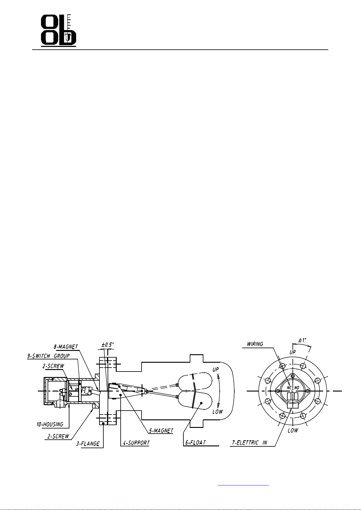
Carry out regular cleaning of the float (6) and of the magnet (5) on the fluid side. Make sure there are no scales or
filth between the magnet and the process flange (3) and between the magnet and the fulcrum supports (4) that
prevent the float
from moving freely.
ROUTINE INSPECTION OF THE CONTACT
When the instrument is removed for routine cleaning, move the float (6) manually to check that the microswitch
switch regularly.
REPLACING THE SWITCH GROUP
The microswitch is an integral part of the s
witch group and never needs to be removed. If the microswitch shows
malfunctioning, the whole switch group
-
supplied as a standard spare
-
needs to be replaced. Remove the housing
(10) from the process flange by means of the screws (1) which fasten it. Re
move the two screws (8) inside the
housing which fasten the switch group and extract it pushing from the terminal block side. Insert the new switch
group taking care that the terminal block is on the side of the electric input (7). The switch group is no
t reversible
and does not run properly if it is held upside down. Screw the unit together again and check for proper operation
like when executing routine inspections.
8. TROUBLE
-
SHOOTING
Series 10 level switches are designed for long fault
-
free life.
If a level switch does not emit the alarm signal, the
tripping unit should be checked and then the body/float as described in the preventive servicing paragraph. If the fault
is not identified after all tests have been carried out, please refer to our afte
r-
sales service.
9. WASTE DISPOSAL
Disposal of the instruments must comply with rules in force with regard to noxious toxic materials as well as to
special materials (PVC , PTFE , PP , PVDF , neoprene, viton , asbestos free joints, steel and metal alloys,
aluminium,
copper, brass, plexiglas and glass).

OFFICINE OROBICHE S.p.A. 3/3
24010 Ponteranica (BG) ITALY
-
via Serena, 10 Tel. 0039/35/453021
1 Fax 0039/35/570546
www.officineorobiche.it
e
-
mail: [email protected]
*****************************************************************************************************************************************************************
JULY ’05
Under r
eserve of modification
IST/019
-I
10. GUARANTEE
All series 10 switches are guaranteed free from faulty material and workmanship for 5 years from the date of
dispatch. If an instrument shows malfunctioning and is returned within the
time indicated and if the cause for the fault
is covered by guarantee, OFFICINE OROBICHE will carry out all necessary operations (even replacing the
instrument) without any cost to the purchaser except for transport of the instrument.
OFFICINE OROBICHE are
not answerable for an incorrect use of its products and in such a case all claims will be
rejected. Any direct damages and/or expenses arising from an incorrect installation or use cannot be assigned or
charged to OFFICINE OROBICHE.
FINAL NOTES
All instr
uments are supplied fully assembled and with all accessories required. Some parts are supplied separately
only in special cases. The consignment must therefore be inspected carefully on arrival and any differences reported
promptly.
When ordering spare pa
rts, always indicate the appliance’s serial number. This number is shown on the data plate
fixed to the housing. It is a five
-
digit number preceded by the letter “F” (e.g. F47521).
N.B.
IN CASES WHEN THE INSTRUMENTS ARE MEANT TO BE USED IN AREAS FEATURIN
G
POTENTIALLY EXPLOSIVE ATHMOSPHERES, THE USER SHALL COMPLY WITH THE
ADDITIONAL
SAFETY INSTRUCTIONS
ATTACHED TO THE STANDARD ONES.
Table of contents
Other OFFICINE OROBICHE Switch manuals
Popular Switch manuals by other brands

EUCHNER
EUCHNER STP AS1 Series operating instructions

Transition Networks
Transition Networks SISTP1040-342-LRT quick start guide

LEGRAND
LEGRAND 3 109 53 installation manual

Comtech EF Data
Comtech EF Data CRS-180 manual

steute
steute RF BF 74 SW868 Mounting and wiring instructions

Cabletron Systems
Cabletron Systems GIGAswitch GSR-16 User's reference manual

DEFA
DEFA WarmUp Bluetooth user manual

SMC Networks
SMC Networks TigerSwitch SMC8648T Technical specifications

GMI
GMI D6034S instruction manual

Ametek
Ametek IntelliPoint RF RNT Series Assembly, installation and operating instructions

Zte
Zte ZXR10 5900E Series user manual

GeoVision
GeoVision GV-POE0801 user manual