Ogawa SPIN PRO 81.6 User manual

1
USER MANUAL

2
Product name
Spin Pro B1.6
Model
AC 3211
Packing dimension (cm)
100Lx25Wx66.5H
Product dimension (cm)
111Lx61Wx136H
Net weight
27kg
Gross weight
27.7kg
Max load
110kg
Colour
Black
Material
Steel+Plastic
Product Specification

3
1. Warranty is not transferable.
2. This warranty is effective only if the product is purchased from Ogawa or its authorized
dealers.
3. Proof of purchase (original receipt) is required for all warranty repairs.
4. All implied warranties, including but not limited to these implied warranties of fitness and
merchantability, are limited to one (1) year from the date of purchase.
5. Damage due to misuse, improper treatment and unauthorized modification and repairs are
not covered by this warranty.
6. Warranty does not cover accessories and add-ons, which do not belong to this product.
7. Warranty is not effective rental, business, commercial, institutional, or other non-residential
users.
8. A ll services covered by this warranty must be approved by Ogawa and repaired by
authorized technicians only.
9. If replacement parts for defective materials are not available. Ogawa reserves the right to
make substitutions in lieu of repair or replacement.
Warranty Claim

4
Basic precautions should always be followed, including the following important
safety instructions when using this equipment. Read all instructions before using
this equipment.
1.
Read all instructions and follow it carefully before using this equipment. Make sure the
equipment is properly assembled and tightened before use.
2.
Before exercise, in order to avoid injuring the muscle, warm-up exercises are
recommended.
3.
Please make sure all parts are not damaged and fixed well before use. This equipment
should be placed on a flat surface when using. Using a mat or other covering material on
the ground is recommended.
4.
Please wear proper clothes and shoes when using this equipment; do not wear clothes
that might catch any part of the equipment.
5.
Do not attempt any maintenance or adjustments other than those described in this
manual. Should any problems arise, discontinue use and consult your local dealer.
6.
Be careful when step on or leave the pedal always hold the handlebars first. Make the
pedal at your side at the lowest position, step on the pedal, and stride over the main
frame then step on the other pedal. After exercise, please also make one pedal at the
lowest position and leave your foot on the higher pedal first and then another.
7.
Do not allow the dumbbells drop freely to the ground. Damage to the product and
possible personal injury may occur.
8.
Do not use the equipment outdoors. It is not a commercial model.
9.
This equipment is for household use only.
10.
Only one person at a time should use this equipment.
11.
If you feel any chest pains, nausea, dizziness, or short of breath, you should stop
exercising immediately and consult your physician before continuing.
12.
Care should be taken in mounting or dismounting the equipment.
13.
Do not allow children to use or play on the equipment.Keep children and pets away
from the equipment while in use. This machine is designed for adults use only.The
minimum free space required for safe operation is not less than two meters.
14.
The maximum weight capacity for this product is 110 kgs.
WARNING: Before beginning any exercise program consult your physician.
This is especially important for the people who are over 35 years old or who have
pre-existing health problems. Read all instructions before using any fitness
equipment.
CAUTION:Read all instructions carefully before operating this product. Retain
this Owner’s Manual for future reference.
IMPORTANT SAFETY INSTRUCTIONS
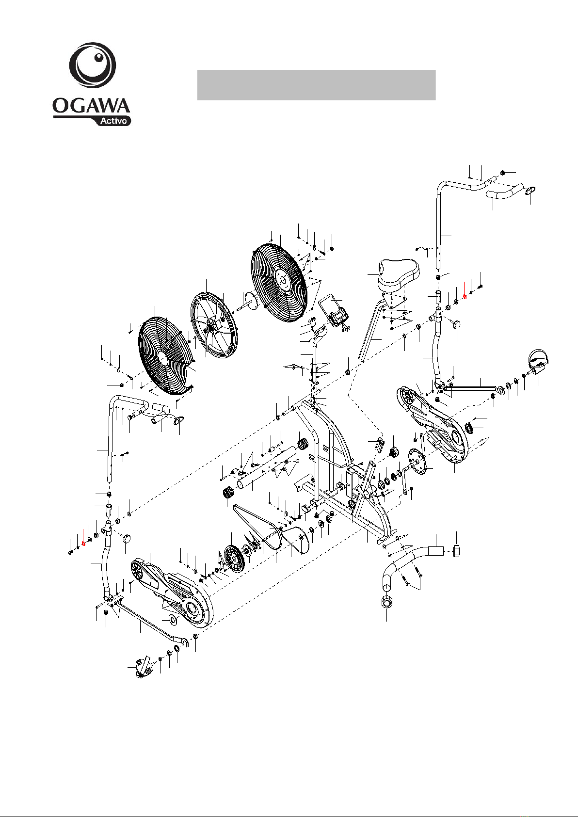
5
No.
Description
Qty
No.
Description
Qty
01
Main Frame
1
32
Handrail Arm Adjustable Knob M8
2
02
Computer Post
1
33
Hexagon Bolt M8×48
2
03
Left Handrail Arm
1
34
Plug Ø 32
2
04
Right Handrail Arm
1
35
Spacer Bushing Ø18xØ14xØ8x10
4
05
Left Handrail
1
36
Flange Nut M10×P1.0
4
06
Right Handrail
1
37
Eyebolt M6×36
4
07
Left Foot Bar
1
38
U-shape Bracket
4
08
Right Foot Bar
1
39
Spring Washer Ø 6
8
09
Front Stabilizer Ø50
1
40
Nut M6
4
10
Rear Stabilizer Ø50
1
41
Cross Pan Head Screw M6×10
5
11
Left Foot Pedal
1
42
Left Cover for Flywheel Ø 490
1
12
Left Foot Pedal
1
43
Hexagon Nut M10×P1×5
4
13
Left Cover
1
44
Circlip Φ10
4
14
Right Cover
1
45
Bearing 6000Z
4
15
Seat Post
1
46
Flywheel Ø 415×55
1
16
Seat Cushion
1
47
Axle Sleeve
1
17
Flat Washer Ø8ר16×1.5
7
48
Right Cover for Flywheel Ø 490
1
18
Nylon Nut M8
5
49
Hexagon Bolt M6×15
4
19
Computer
1
50
Belt Pulley with crank Ø 170
1
20
Extension Sensor Wire L=450mm
3
51
Gear
1
21
Wire Plug Ø 12
5
52
Axle Φ10×140
1
22
Cross Pan Head Screw M5×10
2
53
Belt PJ390/J5
1
23
Hexagon Bolt M8×30
2
54
Chain
1
24
Handrail Arm End Cap Ø25
6
55
Hexagon Flat Nut 7/8"
1
25
Handrail Arm Foam Grip
Ø 24ר 35×280
2
56
Washer Ø 35×2
1
26
Plastic Bushing Ø 32×1.5
2
57
Puller Bushing 15/16"
1
27
Hexagon Bolt M10×20
2
58
Bearing Φ44.5
2
28
Spring Washer
Ø 19.5ר11.5×2.5
2
59
Bearing Bush Ø 55.6×16
2
29
Washer Ø 28ר 16×δ5
2
60
Puller Bushing 7/8"
1
30
Bushing Ø 28ר 16×16
8
61
Flat Washer Ø 40×2.8
1
31
Wave Washer Ø 26ר 16×δ0.3
2
62
Chain Pulley with Crank Ø 165
1
PARTS LIST

6
No.
Description
Qty
No.
Description
Qty
63
Seat Height Adjustable Knob M16
1
78
Crank Cover Ø 60
2
64
Seat Post Plastic Bushing
50×25×1.5
1
79
Cross Pan Head Tapping Screw
ST4.2×20
6
65
End Cap for Main Frame
2
80
Cross Countersunk Head
Tapping Screw ST4.2×20
2
66
End Cap for Front Stabilizer Ø 50
2
81
Rotation Rod
1
67
Hexagonal Bolt M6×45
2
82
Left Nylon Nut
1
68
Movable Wheel
Ø 22ר 6.5×30.5
2
83
Right Nylon Nut
1
69
Bolt M10×56
4
84
Cross Pan Head ScrewM5×10
5
70
Curve Washer Ø 10ר 20×2.0
4
85
Nylon Nut M5
5
71
Cap Nut M10
4
86
Nylon Nut M6
6
72
End Cap for Rear Stabilizer Ø 50
2
87
Cross Countersunk Head Self-drilling
Tapping Screw ST4.2×20
2
73
Sensor L=350mm
1
88
Flat Washer Ø 5ר9×0.8
2
74
Cross Pan Head Self-tapping
Screw ST2.9×9.5
2
89
Hand pulse Sensor with Wire
L=1100mm
2
75
Sensor Wire L=500mm
1
90
Flat Washer Ø 10ר25×2.0
1
76
Washer Ø 24ר 13×4.0
2
77
Bushing Ø 16ר 13×14.5
2

7
Spanner Spanner with Phillips Screwdriver
S13- S17-S19 1PC S13-S14-S15 1PC
Allen Wrench S6 2PCS
(69) Bolt M10x56 4PCS
(70) Curve Washer Ø 10ר 20×2.0 4PCS
(71) Cap Nut M10 4PCS
(63) Seat Height Adjustment Knob M16 (32) Handrail Arm Adjustment Knob M8
1PC 2PCS
HARDWARE BAG

8
25
24
36
37
38
42
46
44
47
48
40 39 38 36
37
43
19
21
22
02
23
17
30
30
67
68
86
86
68
67
30
31
24
26
30
29
28
27
32
35
34
33
07
78
79
17 18
76
77
87
13 49
50
51
52
53
54
72
69
10 72
82
62
74
73
59
6061
63
64
14
79
78
79
87
08
77
12
33
35
34
18
17
32
30
31
3029
28 27
76
45
44
36
37
38
39
40
86
39
40
38
37
36
65
11
03
39
40
45
43
44
45
41
04
24
25
24
26
41
20
75
55
56 5758
59
01
05
06
83
65
66
66
09
45
44
43
80
80
71
70
39
43
58
69
70 71
24
21
81
84
85
85
85
84
84
84
84
88
88
87
89
88
88
87
89
20
21
21
21
17
18
15
16
90
90
EXPLODED DRAWING

9
01
69
10
71
70
69
70 71
09
75
Step 1:Front and Rear Stabilizers Installation
Attach the Rear Stabilizer (10) onto the Main Frame (1) with two M10 Cap Nuts (71), two Ø
10ר 20×2.0 Curve Washers (70) and two M10×56 Bolts (69). Tighten with the Spanner
provided.
Attach the Front Stabilizer (9) onto the Main Frame (1) using two M10 Cap Nuts (71), two Ø
10ר 20×2.0 Curve Washers (70) and two M10×56 Bolts (69). Tighten with the Spanner
provided.
Tool:
Spanner S13-S17-S19
ASSEMBLY INSTRUCTIONS

10
Tool:
Allen Wrench S6 Spanner S13-S17-S19
Spanner with Phillips Screwdriver S13-S14-S15
29
28 27
04
32
06
81
03
31
31
29
28
27
32 01
05
07
08
11
82
12
83
75
62 87
77 76
88
76
77
87
88
90
90

11
Step 2: Left and Right Foot Pedals, Left and Right Foot Bar, Left and Right Handrail
Arm Installation
Remove two M10×20 Hexagon Bolts (27), two Ø 19.5ר11.5×2.5 Spring Washers (28),
two Ø 10ר25×2.0 Flat Washer (90), two Ø28ר 16×δ5 Washers (29), and two Ø 26ר
16×δ0.3 Wave Washers (31) from the Rotation Rod (81).
Insert the Rotation Rod (81) into the hole of the Main Frame (1). Attach two Ø 26ר 16×δ0.3
Wave Washers (31) onto the Rotation Rod (81), then attach L & R Handrails (5)(6) onto the
Rotation Rod (81) using two Ø28ר 16×δ5 Washers (29), two Ø 10ר25×2.0 Flat Washer
(90), two Ø 19.5ר11.5×2.5 Spring Washers (28), and two M10×20 Hexagon Bolts (27).
Tighten with Allen Wrench provided.
Remove Flat Washer Ø 5ר9×0.8 (88), Ø 24ר 13×4.0 Washer (76), 16ר 13×14.5 Bushing
(77), Cross Countersunk Head Self-drilling Tapping Screw ST4.2×20 (87), and Right Nylon
Nut (83) from the Right Foot Pedal (12).
Attach the Right Foot Pedal (12) onto the right side of Crank (62) using Flat Washer Ø
5ר9×0.8 (88), Ø 24ר 13×4.0 Washer (76), 16ר 13×14.5 Bushing (77), Right Foot Bar (8),
Cross Countersunk Head Self-drilling Tapping Screw ST4.2×20 (87), and Right Nylon Nut
(83). Tighten the Right Foot Pedal (12) by hand clockwise and tighten the Right Nylon Nut
(83) counter-clockwise with Allen Wrench and Spanner provided.
Repeat the same procedure to attach the Left Foot Pedal (11) onto the left side of Crank (62),
tighten the Left Foot Pedal (11) counter-clockwise and tighten the Left Nylon Nut (82)
clockwise with Allen Wrench and Spanner provided.
NOTE: Do not turn the Left pedal clockwise to tighten or will strip the threads.
Insert the Right Handrail Arm (4) into the Plastic Bushing on the tube of the Right Handrail (6)
using M8 Handrail Arm Adjustable Knob (32).
Repeat the same procedure to assemble the Left Handrail Arm (3).

12
Step 3: Seat Post, Seat Cushion Installation
Remove three Ø8ר16×1.5 Flat Washers (17) and three M8 Nylon Nuts (18) from under the
Seat Cushion (16). Attach the Seat Post (15) to the Seat Cushion (16) using three Ø8ר16×
1.5 Flat Washers (17) and three M8 Nylon Nuts (18). Tighten with the Spanner with Phillips
Screwdriver provided.
Insert the Seat Post (15) into the Seat Post Plastic Bushing on the tube of the Main Frame (1)
and then attach the M16 Seat Height Adjustable Knob (63) onto the tube of the Main Frame (1)
by turning it in a clockwise direction to lock the Seat Post (15) in the suitable position.
Adjusting the Seat Height
Turn the M12 Seat Height Adjustable Knob (63) in a counterclockwise direction to release the
Seat Post (15) and then slide the Seat Post (15) up or down slightly to the desired hole for the
suitable position.Lock the Seat Post (15) in place by tightening the M12 Seat Height Adjustable
Knob (63) in a clockwise direction.
NOTE: When adjusting the height of seat post, make sure the seat post plastic
bushing does not exceed the mark line on the seat post.
Tool:
Spanner with Phillips
Screwdriver S13-S14-S15
63
01
75
17
18
15
16

13
Step 4: Computer Post Installation
Connect the Sensor Wire (75) with Extension Sensor Wire (20).
Remove two Ø8ר16×1.5 Flat Washers (17) and two M8×30 Hexagon Bolts (23) from the
Main Frame (1).
Attach the Computer Post (2) onto the Main Frame (1) with two Ø8ר16×1.5 Flat Washers
(17) and two M8×30 Hexagon Bolts (23). Tighten with the S6 Allen Wrench provided.
Connect two Hand pulse Sensor with Wire (89) with two Extension Sensor Wire (20).
Connect the Extension Sensor Wire (20) with the wires of the Computer (19).
Remove two M5×10 Cross Pan Head Screws (22) from the Computer (19).
Then attach the Computer (19) onto the top end of Computer Post (2) use two M5×10 Cross
Pan Head Screws (22).Tighten with the Spanner with Phillips Screwdriver provided.
Tool:
Allen Wrench S6
Spanner with Phillips Screwdriver
S13-S14-S15
19
22
02
23
17
20
75
01
89
20

14
Cleaning
The bike can be cleaned with a soft clean damp cloth. Do not use abrasives or solvents on
plastic parts. Please wipe your perspiration off the bike after each use. Be careful not get
excessive moisture on the computer display panel as this might cause an electrical hazard or
electronics to fail.
Please keep the bike, especially the computer console out of direct sunlight to prevent
screen damage.
Before use and every week, please inspect all assembly bolts and pedals on the
machine to make sure they are tightened properly.
Storage
Store the bike in a clean and dry environment away from children.
TROUBLESHOOTING
PROBLEM
SOLUTION
There is no display on the computer
console.
1. Remove the computer console and verify
the wire that comes from the computer
console is properly connected to the wire
that comes from the handlebar post.
2. Check if the batteries are correctly
positioned and battery springs are in
proper contact with batteries.
3. The batteries in the computer console may
be dead. Change to new batteries.
The bike wobbles when in use
Turn the rear stabilizer end cap on the rear
stabilizer as needed to level the bike.
The bike makes squeaking noise when in
use.
The bolts may be loose on the bike. Please
inspect all of the bolts and tighten any loose
bolts.
MAINTENANCE

15
The WARM-UP is an important part of any workout.The purpose of warming up is to prepare
your body for exercise and to minimize injuries. Warm up for two to five minutes before
aerobic exercising. It should begin every session to prepare your body for more strenuous
exercise by heating up and stretching your muscles, increasing your circulation and pulse rate,
and delivering more oxygen to your muscles.
COOL DOWN at the end of your workout, repeat these exercises to reduce soreness in tired
muscles. The purpose of cooling down is to return the body to its resting state at the end of
each exercise session. A proper cool-down slowly lowers your heart rate and allows blood to
return to the heart.
HEAD ROLLS
Rotate your head to the right for one count, you should feel a stretching
sensation up the left side of your neck. Then rotate your head back for
one count, stretching your chin to the ceiling and letting your mouth open.
Rotate your head to the left for one count, then drop your head to your
chest for one count.
SHOULDER LIFTS
Lift your right shoulder toward your ear for one count. Then lift your
left shoulder up for one count as you lower your right shoulder.
SIDE STRETCHES
Open your arms to the side and lift them until they are over your head.
Reach your right arm as far toward the ceiling as you can for one
count. Repeat this action with your left arm.
WARM UP AND COOL DOWN ROUTINE

16
QUADRICEPS STRETCH
With one hand against a wall for balance, reach behind you and pull
your right foot up. Bring your heel as close to your buttocks as
possible. Hold for 15 counts and repeat with left foot.
INNER THIGH STRETCH
Sit with the soles of your feet together and your knees pointing
outward. Pull your feet as close to your groin as possible.
Gently push your knees toward the floor.Hold for 15 counts.
TOE TOUCHES
Slowly bend forward from your waist, letting your back and
shoulders relax as you stretch toward your toes. Reach as far as
you can and hold for 15 counts.
HAMSTRING STRETCHES
Extend your right leg. Rest the sole of your left foot
against your right inner thigh. Stretch toward your toe as
far as possible. Hold for 15 counts. Relax and then re peat
with left leg.
CALF/ACHILLES STRETCH
Lean against a wall with your left leg in front of the right and
your arms forward. Keep your right leg straight and the left
foot on the floor; then bend the left leg and lean forward by
moving your hips toward the wall. Hold, then repeat on the
other side for 15 counts.

17
MALAYSIA
Healthy World Lifestyle Sdn Bhd
No.22 Jalan Anggerik Mokara 31/47
Kota Kemuning, 40460 Shah Alam
Selangor Darul Ehsan, Malaysia.
Tel: +603-5121 4286
Fax: +603-5121 4386
CONTACT US
This manual suits for next models
1
Table of contents
Other Ogawa Exercise Bike manuals