Ohio Medical Push-To-Set PTS-CVR User manual

Vacuum Regulator, Push-To-Set™
Continuous (PTS-CVR)
Service Manual
Adult | Pediatric | Neonatal | C.A.S.S.
8700-0006-000 (Rev. 12) 08/2020
Two Mode
MAX
®
MAX
High Flow
High Vacuum
10
20
30
40
50
60
70
80
90
100
100
200
300
400
500
600
700
-
k
P
a
-
m
m
H
g
®
MAX
L
L
M
M
H
H
F
F
MEDICAL VACUUM
®
®
®
High Flow
High Vacuum
10
20
30
40
50
60
70
80
90
100
100
200
300
400
500
600
700
-
k
P
a
-
m
m
H
g
®
L
L
M
M
H
H
F
F
MEDICAL VACUUM
®
®
ANSI
Analog
Adult (Standard) - (1224)
Adult (High) - (1226)
Digital
Adult (Standard) - (1324)
Adult (High) - (1326)
ANSI
Analog
Adult (Standard) - (1225)
Adult (High) - (1330)
C.A.S.S. - (1227)
Neonatal - (1231)
Pediatric - (1234)
Digital
Adult (Standard) - (1325)
Adult (High) - (1430)
C.A.S.S. - (1327)
Neonatal - (1331)
Pediatric - (1334)
ISO
Analog
Adult (High) - (1230)
Neonatal - (1232)
Pediatric - (1235)
Digital
Adult (High) - (1337)
Neonatal - (1332)
Pediatric - (1335)
Three Mode
ISO
Analog
Adult (High) - (1229)
Digital
Adult (High) - (1329)
®

8700-0006-000 (Rev. 12) 08/20202
User Responsibility
This Product will perform as described in this operating manual and accompanying labels and/or inserts, when
assembled, operated, maintained and repaired in accordance with the instructions provided. This Product must
be checked periodically. A defective product should not be used. Parts that are broken, missing, worn, distorted
or contaminated should be replaced immediately. For service advice, Ohio Medical recommends that a telephone
request be made to the nearest Ohio Medical Regional Service Center. This product and any of its parts should
only be repaired using written instructions provided by Ohio Medical or by Ohio Medical trained personnel. The
Product must not be altered without the prior written approval of Ohio Medical’s Quality Assurance Department.
The user of this Product shall have the sole responsibility for any malfunction which results from improper use,
faulty maintenance, improper repair, damage, or alteration by anyone other than Ohio Medical.
AAA A 12345 This alpha character indicates the year of product manufacture and when the serial number
was assigned; “L” = 2007, “M” = 2008, “N” = 2009, etc. “I” and “O” are not used.
Safety Instructions
This manual provides you with important information about the Push-To-SetTM Continuous Vacuum Regulator
(PTS-CVR). To ensure the safe and proper use of this device, READ and UNDERSTAND all of the safety and
operating instructions. IF YOU DO NOT UNDERSTAND THESE INSTRUCTIONS, OR HAVE ANY QUESTIONS,
CONTACT YOUR SUPERVISOR, DEALER OR THE MANUFACTURER BEFORE ATTEMPTING TO USE THE
DEVICE.
Intended Use
The vacuum regulator is intended to be used in the medical facility as a means to evacuate media (i.e. uids)
from the body. DO NOT use this vacuum regulator for anything other than its intended use.

38700-0006-000 (Rev. 12) 08/2020
Table of Contents
1/Precautions
1.1 Denitions .............................................................. 4
1.2 Warnings................................................................ 5
1.3 Cautions................................................................. 5
2/Scope
2.1 ANSI Vacuum Regulators (North American).......... 6
2.2 ISO Vacuum Regulators (International) ................. 6
3/Description and Specications
3.1 Description............................................................. 7
3.2 Specications......................................................... 8
4/Cleaning and Disinfection
4.1 Cleaning and Disinfection ...................................... 9
4.1.1 Routine Exterior Cleaning............................. 9
4.1.1.1 Approved Cleaning Solutions ........... 9
5/Troubleshooting ................................................ 10
6/Service - Disassembly and Assembly
6.1 Service Tools and Equipment .............................. 12
6.2 Continuous Vacuum Regulators (All Models) ...... 12
6.2.1 Disassembly ............................................... 12
6.2.2 Assembly .................................................... 12
6.3 Suction Level Limit Setting (PED/NEO/C.A.S.S.
Models ONLY) ............................................. 13
6.3.1 Vacuum Relief Valve Adjustment ................ 13
6.3.2 Vacuum Limiting Set Screw Adjustment
(PED and NEO Units ONLY).............. 13
6.3.2.1 Pediatric Unit ................................. 13
6.3.2.2 Neonatal Unit ................................. 13
6.4 Regulator Module ................................................ 13
6.4.1 Disassembly ............................................... 14
6.4.2 Assembly .................................................... 14
6.5 Digital Gauge ....................................................... 14
6.5.1 Removal of Batteries .................................. 14
6.5.2 Inserting Batteries....................................... 14
7/Service Checkout Procedure
7.1 Set-up .................................................................. 15
7.2 Push-To-SetTM Test............................................... 15
7.3 Gauge Test........................................................... 15
7.3.1 High Vacuum Gauges ONLY ...................... 15
7.3.2 Standard and PED/NEO/C.A.S.S. Vacuum
Gauges ONLY............................................. 15
7.4 Regulation Test .................................................... 16
7.5 Maximum Vacuum Test (PED/NEO/C.A.S.S.
Models ONLY) ............................................. 16
7.6 Bleed Test ............................................................ 16
7.7 Leak Test ............................................................. 16
7.7.1 Supply Side................................................ 16
7.7.2 Patient Side ............................................... 17
7.8 Flow Test.............................................................. 17
8/Maintenance
8.1 General Maintenance of Suction Equipment ....... 18
8.2 Recommended Maintenance............................... 18
8.3 Repair Policy........................................................ 18
8.4 Technical Assistance............................................ 19
8.5 Return Instructions............................................... 19
8.6 Installation Procedure for Adapters/Probes
and Fittings .......................................................... 19
9/Ordering Information
9.1 Illustrated Parts.................................................... 20
9.2 Accessories...........................................................22
10/Electromagnetic Compatibility Declara-
tions for PTS Digital
10.1 Guidance & Manufacturer’s Recommendation...23
10.2 Immunity to Proximity Fields...............................24

8700-0006-000 (Rev. 12) 08/20204
1/Precautions
1.1 Denitions
Note: A Note provides additional information to clarify a point in the text.
Important: An Important statement is similar to a note but of greater emphasis.
CAUTION: A CAUTION statement is used when the possibility of damage to the equipment exists.
WARNING: A WARNING statement is used when the possibility of injury to the patient or the operator exists.
High Flow
High Vacuum = high ow, high vacuum
High Flow
Low Vacuum = high ow, low vacuum
| (ON) = on
O (OFF) = o
⚠ Consult Instructions for Use
Serial Number
Manufacturer
Abbreviations Used In This Manual
CCW Counter-clockwise (decrease)
CW Clockwise (increase)
CVR Continuous Vacuum Regulator
MAX Full Line Vacuum
inHg Inches of mercury
kPa Kilopascals (kPa x 7.50 = mmHg)
L/min Liters per minute
mmHg Millimeters of mercury (mmHg x 0.133 = kPa)
mL Milliliters
°C Degrees Celsius
°F Degrees Fahrenheit
N-m Newton-Meter (N-m x 0.737 = ft-lb)
ft-lb Foot-Pound Force (ft-lb x 1.356 = N-m)
oz Ounces
DISS Diameter Index Safety System
OES Oxequip®Suction
NCG National Compressed Gases (Chemetron)
NPT National Pipe Thread (USA)
NPTF National Pipe Thread Female (USA)
MPTS Multi-Purpose Therapy Stand
gal Gallon
PTFE Polytetrauoroethylene
PTS Push-To-SetTM
IFU Instructions for Use

58700-0006-000 (Rev. 12) 08/2020
1.2 Warnings
This device should be repaired only by qualied Ohio
Medical or Ohio Medical-trained, qualied personnel,
using only Ohio Medical recommended parts. There
are risks associated with using anything other
than Ohio Medical parts. Ohio Medical will assume
no responsibility for incidents which may occur if
the product was not repaired in accordance with
procedures authorized by Ohio Medical.
If the vacuum regulator is repaired or disassembled
in any manner, the service checkout procedure
must be performed before using the equipment on a
patient.
After patient use, if regulator is contaminated then
handle in accordance with you hospital’s infection
control policy.
To reduce transportation personnel and/or service
personnel exposure to hazardous contamination,
DO NOT ship any suction equipment that has been
contaminated.
Do not use this device in the presence of ammable
anesthetics. Static charges may not dissipate and a
possible explosion hazard exists in the presence of
these agents.
Connection to positive pressure sources such as
oxygen and medical air, even momentarily, could
injure the patient or operator.
Ohio Medical will assume no responsibility for
incidents which may occur if the product is not used
in accordance with product labeling.
To help prevent aspirate from entering the device,
wall outlet and pipeline equipment, a safety trap
should be attached prior to its use. Aspirate in the
regulator, wall outlet and pipeline equipment may
impair its operations. The use of the safety trap and
suction lter will help prevent this and extend the life
of suction equipment.
1.3 CAUTION
Do not use any Loctite® products or any products
which contain Methacrylate Ester as an active
ingredient to seal the threads on the adapters/probes
and ttings.
Use of lubricants other than recommended may
degrade plastic or rubber components.
Do not steam autoclave or liquid sterilize the
regulator. Severe impairment to the operation of the
regulator will result. Do not use harsh chemical or
cleaning solution. Do not spray cleaners directly onto
suction regulators. Only use chemical recommended
in this manual.
If any evidence of damage is found, repair as
necessary or contact your authorized service
provider.
Connection to positive pressure sources such as
oxygen and medical air, even momentarily, could
damage the equipment.
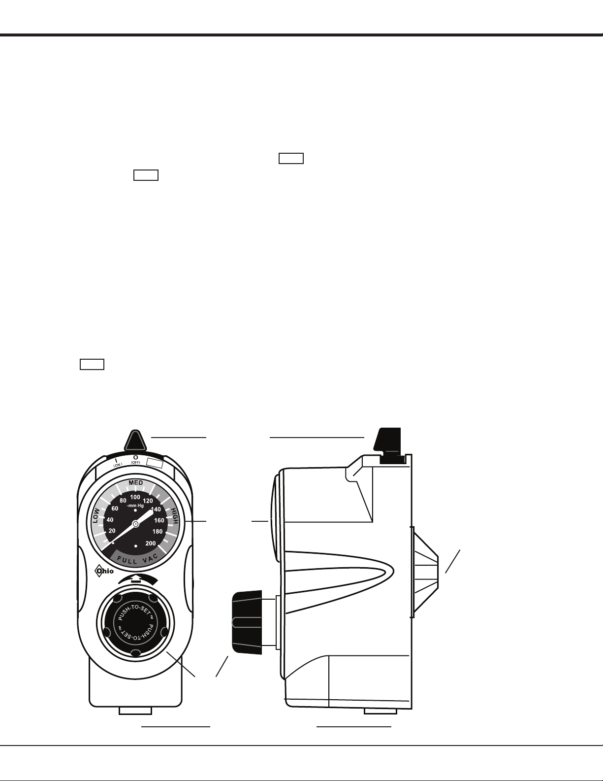
The suction control knob must be completely pushed in to
adjust the vacuum level. Failure to do so may damage the
vacuum regulator.
Not for transport use: The categories of eld and
transport user are specically dened in ISO 10079-
3. “Field” means use at accidents or emergencies
outside a hospital. “Transport” means use in
ambulances, cars and airplanes. These situations
may expose the equipment to uneven support,
water, dirt, and mechanical shock and temperature
extremes. Ohio Medical Suction equipment has not
been tested to comply with the specic requirements
of these categories.
Note: Ohio Medical requests that parties acquiring
this device:
Report the device’s purchase, receipt in trade, return
after sale, loss, destruction, or retirement.
Contact your Ohio Medical customer service
representative to obtain manual updates.
Authorized Service Center / Customer Service
Call 1-866-549-6446 or +1 847-855-0500 for service
and repair information.
1/Precautions

8700-0006-000 (Rev. 12) 08/20206
This service manual contains service, maintenance and parts information on all models of the Push-To-SetTM Continuous
Vacuum Regulator.
2.1 ANSI Vacuum Regulators (North American)
2.2 ISO Vacuum Regulators (International)
®
L
L
M
M
H
H
F
F
MEDICALVA CUUM
®
®
Analog (1225) Digital (1325)
Standard Two Mode
Continuous
Adult
Analog (1224) Digital (1324)
Standard Three Mode
Continuous
Adult
MAX
®
MAX
L
L
M
M
H
H
F
F
MEDICALVA CUUM
®
®
MAX
High Flow
High Vacuum
10
20
30
40
50
60
70
80
90
100
100
200
300
400
500
600
700
-
k
P
a
-
m
m
H
g
®
MAX
L
L
M
M
H
H
F
F
MEDICAL VACUUM
®
®
Analog (1229) Digital (1329)
High Three Mode
Continuous
Adult
MAX
-mm Hg
100
200
500
700
300
400
600
MAX
Analog (1226) Digital (1326)
High Three Mode
Continuous
Adult
MAX
L
L
M
M
H
H
F
F
MEDICALVA CUUM
®
®
2/Scope
High Flow
High Vacuum
10
20
30
40
50
60
70
80
90
100
100
200
300
400
500
600
700
-
k
P
a
-
m
m
H
g
®
Analog (1230) Digital (1337)
High Two Mode
Continuous
Adult
L
L
M
M
H
H
F
F
MEDICAL VACUUM
®
®
Analog (1330) Digital (1430)
High Two Mode
Continuous
Adult
-mm Hg
100
200
500
700
300
400
600
MAX
L
L
M
M
H
H
F
F
MEDICALVA CUUM
®
®
Analog (1231) Digital (1331)
Low Two Mode
Continuous
Neonatal
Analog (1234) Digital (1334)
Low Two Mode
Continuous
Pediatric
Analog (1227) Digital (1327)
Standard Two Mode
Continuous
C.A.S.S.
Low Vacuum
100 120
140
160
80
60
40
20
mm Hg
L
O
W
M
E
D
H
I
G
H
C.A.S.S.
L
L
M
M
H
H
F
F
MEDICALVA CUUM
®
®C.A.S.S.
Low Vacuum
100 120
140
160
80
60
40
20
mm Hg
L
O
W
M
E
D
H
I
G
H
L
L
M
M
H
H
F
F
MEDICALVA CUUM
®
®
Low Vacuum
100 120
140
160
80
60
40
20
mm Hg
L
O
W
M
E
D
H
I
G
H
L
L
M
M
H
H
F
F
MEDICALVA CUUM
®
®
Analog (1232) Digital (1332)
Low Two Mode
Continuous
Neonatal
-
k
P
a
-
m
m
H
g
2
4
6
8
10
12
14
16
18
140
20
40
60
80
100
120
20
High Flow
Low Vacuum
L
L
M
M
H
H
F
F
MEDICAL VACUUM
®
®
Analog (1235) Digital (1335)
Low Two Mode
Continuous
Pediatric
-
k
P
a
-
m
m
H
g
2
4
6
8
10
12
14
16
18
140
20
40
60
80
100
120
20
High Flow
Low Vacuum
L
L
M
M
H
H
F
F
MEDICAL VACUUM
®
®

78700-0006-000 (Rev. 12) 08/2020
3/Description and Specications
3.1 Description
The PTS-CVR is a lightweight, compact unit used throughout the hospital primarily for pharyngeal/tracheal suctioning
(airway management). Various models provide regulated or full-line vacuum for hospital suction procedures.
There are several models of the PTS-CVR. All models contain a vacuum gauge which indicates suction supplied by
the regulator. Each has a positive pressure safety relief valve to prevent pressurization by either failed injector vacuum
(Venturi®) units or inadvertent cross connection to pressurized gasses. In addition, the Low PTS-CVR models include a
vacuum relief valve to limit maximum suction.
Some models operate in a regulated or non-regulated MAX mode. Others operate only in the regulated mode.
In the non-regulated MAX mode, the vacuum source is connected directly to the tting/patient port. The regulator module
is bypassed and full-line vacuum is provided.
In the regulated mode, the vacuum source is connected through the regulator module which functions as an automatic
valve. Turning the suction control knob adjusts the position of the regulator module and allows selection of a
predetermined level of suction when set according to instructions.
During use, as the ow requirement increases, the valve automatically opens to maintain suction at the preset level.
When the ow requirement decreases, the valve automatically closes to maintain suction at the preset level. The same
mechanism compensates for changes in supply vacuum and automatically maintains the pre-set suction level when set
according to instructions.
1. Suction Control Knob - Allows easy adjustment of suction to the patient.
2. Mode Selector Switch - Allows quick and easy mode changes.
a. | (ON) - Suction can be adjusted with the suction control knob.
b. O (OFF) - No suction is supplied to the patient.
c. MAX - Maximum full-line vacuum is supplied to the patient.
3. Vacuum Gauge - The suction level to the patient is displayed during use.
Mode
Selector
Switch
MAX
®
Vacuum
Gauge
Adapter/Probe
Port
Fitting/Patient Port
Suction
Control
Knob

8700-0006-000 (Rev. 12) 08/20208
3/Description and Specications
3.2 Specications
1without ttings at full increase setting depending on supply vacuum and open air ow.
2full scale deection
3full range at 22°C
ENVIRONMENTAL SPECIFICATIONS
Operating Temperature Range: 50 to 104ºF (10 to 40ºC)
Storage Temperature Range: -13 to 158ºF (-25 to 70ºC)
Operating and storage Relative Humidity: 5 to 95% RH (Non-condensing)
Ingress Protection Ratings: IP 20
Gauge Accuracy Gauge Range Analog2Digital3
Standard 0-200 mmHg (0-26.7 KPA) ±5% Full-scale ±1% Full-scale
High 0-760 mmHg (0-101.3 KPA) ±5% Full-scale ±1% Full-scale
Pediatric 0-160 mmHg (0-21.3 KPA) ±5% Full-scale ±1% Full-scale
Neonatal 0-160 mmHg (0-21.3 KPA)
0-100 mmHg (0-13.3 KPA)
±5% Full-scale
-
-
±1% Full-scale
C.A.S.S. 0-160 mmHg (0-21.3 KPA) ±5% Full-scale ±1% Full-scale
Performance
Standard High Pediatric Neonatal C.A.S.S.
Flow rate180 L/min 80 L/min 80 L/min 80 L/min 80 L/min
Positive Pressure
Safety Relief Valve:
Located in the vacuum supply line to prevent pressurization of
the patient connection by failed injector vacuum (Venturi) units, or
inadvertent cross connection to pressured gases.
Physical
Dimensions 6.7”H x 2.8”W x 4.8”D
(17.02 cm x 7.1 cm x 12.2 cm)
Weight 1 lb 4 oz (0.57 kg)
Battery Two 2/3 AA, 3.6V, 1.6 Ah, lithium

98700-0006-000 (Rev. 12) 08/2020
4/Cleaning and Disinfection
4.1 Cleaning and Disinfection
WARNING: After patient use, regulators may be contaminated. Handle in accordance with your hospital’s
infection control policy.
CAUTION: Suctioned uids drawn into a vacuum regulator do not stop in the regulator. They proceed through it into
the wall outlet and pipeline system. Failure to clean and disinfect the wall outlet and pipeline system may result in
damage to this equipment.
4.1.1 Routine Exterior Cleaning
Routine cleaning of the regulator is recommended as a standard procedure after each use. Wipe all exterior surfaces with
a solution of water and mild detergent and/or an approved cleaning solution.
4.1.1.1 Approved Cleaning Solutions
• Sodium Hypochlorite 0.5% (Bleach): Mixture of 13 . oz. of bleach to 1 gallon (128 . oz.) tap water
• Isopropyl Alcohol 70%
• Hydrogen Peroxide 3%
• Cavicide®Ready to use full strength

8700-0006-000 (Rev. 12) 08/202010
5/Troubleshooting
SYMPTOM POSSIBLE CAUSES POSSIBLE SOLUTION
Unit fails to provide
vacuum at patient port
in all modes.
Mode Selector Switch is at O(OFF) position Move mode selector switch [34] to desired
mode.
No Supply Vacuum Check Hospital vacuum level (should be at
least 500 mmHg (66.7 KPA).
Damaged/Clogged Supply side or Patient
side ttings
Replace ttings if damaged/clogged
Retighten/Torque if found loose
Knob fails to return when pushed Push and rotate the knob [2] if stuck
Replace actuator [6], drive gear [5],
Regulator Case [3], OTS assembly [10].
Knob stuck at OFF position (all the way
counter clock wise direction)
Push and Rotate Knob [2] to clock wise
direction
Damaged Regulator Module Regulator Module Assembly [12]
Clogged external lter Replace external lter
Overow protection device is shut o Check(Reset oat)/Replace Overow
protection device
Loose or incorrect set-up Set-up unit correctly without any leak.
Aspirant draw into unit Follow your facilities procedures for handling
contaminated products. (DO NOT SEND
UNIT BACK TO THE MANUFACTURER)
Gauge doesn’t respond
to changes in suction
Gauge assembly is not properly aligned. Ensure gauge assembly [6] is properly
aligned.
Missing/Damaged O-Rings Replace O-Rings [9]
Gauge assembly is damaged Replace gauge assembly [6]
Digital Unit Only:
Depleted batteries
Digital Unit Only:
Replaced Gauge [6]/Batteries
Suction level cannot be
adjusted
Unable to push and rotate knob Push and rotate knob [2] if stuck
Replace actuator [6], drive gear [5],
Regulator Case [3], OTS assembly [10].
Damaged OTS assembly Replace OTS assembly [10]
Regulator module is stuck in full OFF or full
ON position
Rotate the knob [2] to free the Regulator
Module Assembly [12]
Snap cap separated from regulator module
housing.
Reassemble snap cap [28] onto regulator
module housing [34]
Replace snap cap [28] and/or regulator
module housing [34]
Replace Regulator Module Assembly [12]
Damaged/Missing spring inside regulator
module assembly
Replace Regulator module assembly [12]
Damaged/Missing O-ring, Quad-ring on
regulator module
Replace O-ring [35] and/or Quad-ring [36]
Damaged Diaphragm inside regulator
module
Replace Diaphragm [30] or regulator module
assembly [12]
Damaged Regulator Module Assembly Replace Regulator module assembly [12]

118700-0006-000 (Rev. 12) 08/2020
5/Troubleshooting
SYMPTOM POSSIBLE CAUSES POSSIBLE SOLUTION
Erratic gauge movement
resulting from regulator
adjustment
Damaged Diaphragm inside regulator
module
Replace Diaphragm [30] or regulator module
assembly [12]
Damaged/Missing O-ring, Quad-ring on
regulator module
Replace O-ring [35] and/or Quad-ring [36]
Gauge assembly is damaged Replace gauge assembly [6]
Knob stuck in full OFF
or full ON position
Excessive force applied Rotate the knob [2] to free the Regulator
Module Assembly [12]
Suction level can
be adjusted without
pushing the knob in
Damaged drive gear Replace drive gear [5]
Damaged actuator Replace actuator occlude-to-set [6]
Damaged Knob Replace knob [2]
Gauge won’t zero
Damaged gauge assembly Replace gauge assembly [6]
Whistling/buzzing noise
from the unit
Need to apply grease on stem on regulator
module
Apply grease on stem [31]
Gauge responds slowly
to changes in suction/
failed bleed down test
Blocked bleed hole orice Clean bleed hole orice [32]
Damaged gauge assembly Replace gauge assembly [6]
Damaged/Clogged Supply side or Patient
side ttings
Replace ttings if damaged/clogged
Retighten/Torque if found loose
Vacuum relief valve
activates below
specied range
{PED and NEO ONLY}
Damaged regulator case Replace regulator case [3]
Damaged diaphragm Replace diaphragm [30]
Damaged/loose set screw Replace/Adjust set screw 8700-0007-400.
Damaged vacuum relief assembly Replace vacuum relief assembly
6700-0045-700.
Vacuum relief valve
does not activate at
specied range
{PED and NEO ONLY}
Damaged vacuum relief assembly Replace vacuum relief assembly and follow
Section 6.3 suction level limit setting.

8700-0006-000 (Rev. 12) 08/202012
6/Service - Disassembly and Assembly
6.1 Service Tools and Equipment
CAUTION: Use of lubricants other than recommended
may degrade plastic or rubber components.
The following items should be on hand during any service
procedure.
• Supply vacuum: 500 mmHg ± 10 mmHg (67 kPa ±
1.3 kPa) & 80 L/min open air ow minimum
• Supply Vacuum Regulator with Gauge, 760 mmHg
(101.3 kPa) Full Scale
• High Vacuum Calibration Gauge, 760 mmHg (101.3
kPa) Full Scale*(Ohio Medical P/N 6700-0352-800)
• 80 L/min Flowmeter
• Phillips Head Screwdriver, No. 2
• Flat Head Screwdriver, 1/4 inch
• Tubing Clamp
• Bubble Leak Tester
• Tweezers (Filter Remover)
• Wooden Tooth Pick (O-ring Remover)
• Phillips head screwdriver No.1
• Dow Corning®111 grease (Ohio Medical P/N 6700-
0074-200)
• Loctite®242 removable thread locker (Ohio Medical
P/N 0220-5016-300)
• Stop watch
• Open end adjustable wrench
• 10 L/min owmeter
(*) Accuracy: ±1% of full scale deection
6.2 Continuous Vacuum
Regulators (All Models)
6.2.1 Disassembly
WARNING: If the Vacuum Regulator is repaired or
disassembled in any manner, the Service
Checkout Procedure must be performed
before using the equipment on a patient.
WARNING: Clean and disinfect all suction equipment
if contaminated before disassembly to
ensure service personnel are not exposed to
hazardous contamination.
WARNING: When servicing a Low Vacuum Regulator,
perform the Vacuum Relief Valve Adjustment
and Low Vacuum Limit Setting Procedure.
CAUTION: The gauge assembly must be handled with
utmost care to retain its precision. If the lens is
removed, do not rest the gauge on its face.
Note: See Section 9.1 Illustrated Parts
1. Remove the four cover screws from the back of the
regulator.
2. With regulator facing up, carefully pull the cover
assembly o the back body.
3. To remove the gauge assembly, grasp the assembly
and pull straight out. The snap-t lens can also be
removed (if applicable) for replacement.
4. Remove actuator and PTS assembly.
5. To remove the regulator module from the manifold
assembly, rotate the regulator module clockwise.
6. Using tweezers, remove the lter. Replace with a
new lter.
7. Grasp the positive pressure safety relief valve, and
pull it from the back body.
8. Remove the mounting screws from the actuator
support bracket and remove the support bracket,
detent plate and selector switch.
9. Low models ONLY: Grasp the vacuum relief valve
and pull it from the back body.
6.2.2 Assembly
CAUTION: To prevent stripping the plastic threads, place
the screw in the hole and turn counter-clockwise
until it drops into the original thread, then tighten
the screws.
1. Place the positive pressure safety relief valve in
position and push onto the back body.
2. Low models ONLY: Lubricate the vacuum relief valve
O-ring and install it in the valve housing.
3. Lubricate switch with a thin coat of Dow Corning
111 on the overmolded area. Place in manifold with
grease side down.
4. Add detent plate making sure the ngers are on either
side of the switch shaft and pointing down.
5. Place O-ring on post coming up through center of
detent plate and set actuator support bracket over
O-ring. Tighten down with 4 screws.
6. Place cylindrical white lter in corresponding cavity.
7. Screw regulator module counter-clockwise into
manifold.
8. Place PTS assembly in manifold directly below
regulator module.

138700-0006-000 (Rev. 12) 08/2020
6/Service - Disassembly and Assembly
9. Set actuator in brackets of the actuator support
bracket and rest the loop on the top of the PTS
assembly.
10. Place gear over regulator post and rest it on the
actuator.
11. Place lens on gauge with single tab at the top and
the two tabs at the lower portion of the gauge and set
gauge into support bracket.
12. Place cover strip in curved slot inside case.
13. Mate the cover with the manifold. With both thumbs
positioned just below the lens, press rmly to snap
the lens in.
14. Install the 4 cover screws.
6.3 Suction Level Limit Setting
(PED/NEO/C.A.S.S. Models ONLY)
WARNING: This Low Vacuum Limit Setting Procedure
must be followed when repairing Low Vacuum
Regulators. Failure to do this may result in
suction exceeding the prescribed level.
6.3.1 Vacuum Relief Valve Adjustment
1. Remove the cover (see Section 6.2.1 Disassembly).
2. Connect the supply vacuum to the adapter/probe
port.
3. Connect an external vacuum test gauge to the patient
port.
4. Move the mode selector switch to | (ON).
5. Slowly rotate the regulator module to increase the
vacuum level. Note the suction level at which the
relief valve opens. The relief valve should open at
140 mmHg ± 5 mmHg (18.7 kPa ± 0.7 kPa) on the
external test gauge.
6. If adjustment is required, grip the vacuum relief valve
rmly with pliers and rotate the screw about 1/8 turn
with a screwdriver. Repeat the previous step and
check the suction level at which the valve opens.
Note: Clockwise rotation will increase the suction
level at which the relief valve opens. Counter-
clockwise rotation will decrease it.
7. Lock the adjusting screw with a drop of removable
thread locker such as Loctite 242. Repeat step 5 to
verify the vacuum relief valve setting.
8. Re-attach the cover (see Section 6.2.2 Assembly).
WARNING: Excess Loctite®may seal the steel ball to
the seat. This will disable the vacuum relief
valve and may allow suction to exceed the
preset limit.
CAUTION: When Loctite is used on the vacuum relief
safety valve, ensure that it only contacts the
metal parts. Loctite causes many plastic parts to
deteriorate.
6.3.2 Vacuum Limiting Set Screw
Adjustment (PED and NEO Units
ONLY)
6.3.2.1 Pediatric Unit
1. Adjust the regulator until the unit’s gauge reads 135
mmHg (18.0 kPa).
2. Rotate the set screw located above the regulator
knob clockwise until it stops against the regulator
module and then place one drop of Loctite 242 onto
the set screw.
3. Turn the regulator counter-clockwise then clockwise
until it stops against the set screw. Ensure that the
gauge reads 135 mmHg ± 5 mmHg (18.0 kPa ± 0.7
kPa) and that the relief valve does not activate. For
the digital unit, ensure that the gauge reads 135
mmHg ± 2 mmHg (18.0 kPa ± 0.3 kPa).
6.3.2.2 Neonatal Unit
1. Adjust the regulator until the unit’s gauge reads 100
mmHg (13.3 kPa).
2. Rotate the set screw located above the regulator
knob clockwise until it stops against the regulator
module and then place one drop of Loctite 242 onto
the set screw.
3. Turn the regulator counter-clockwise then clockwise
until it stops against the set screw. Ensure that the
gauge reads 100 mmHg ± 5 mmHg (13.3 kPa ± 0.7
kPa) and that the relief valve does not activate. For
the digital unit, ensure that the gauge reads between
99 mmHg and FULL (13.2 kPa and FULL).
6.4 Regulator Module
CAUTION: Do not lubricate any internal components of
the regulator module.
CAUTION: The cap screws can strip the regulator
module housing threads if they are screwed in
too tight.

8700-0006-000 (Rev. 12) 08/202014
6/Service - Disassembly and Assembly
6.4.1 Disassembly
1. Remove the quad-ring from the piston stem and
the O-ring from the housing. Lubricate or replace if
needed.
2. Lift and pull tabs to pry o and remove the cap.
3. Peel the diaphragm from the piston head.
4. With the piston head facing down, lift the housing to
separate.
5. Remove springs from the piston stem.
6.4.2 Assembly
1. With the piston head facing down, place the springs
on the piston stem.
2. Place the housing over the piston and slide the piston
stem into the housing.
3. Place the quad-ring on the tip of the piston stem.
4. Place the O-ring on the housing.
5. Fold the diaphragm and place it on the piston head.
6. Place the cap on the housing and press until it snaps
into place.
6.5 Digital Gauge
Note: Both batteries are positioned with the positive
side facing up relative to the display.
6.5.1 Removal of Batteries
1. Remove digital gauge as described in Section 6.2.1
Disassembly.
2. Using a small at head screwdriver, push batteries
out at a 45oangle.
6.5.2 Inserting Batteries
1. Place negative side of battery into battery slot rst
(battery will be at an angle).
2. Then using a at head screwdriver, gently push in
positive battery contact while sliding battery in place.
WARNING: If the Vacuum Regulator is repaired or
disassembled in any manner, the Service
Checkout Procedure must be performed
before using the equipment on a patient.

158700-0006-000 (Rev. 12) 08/2020
7/Service Checkout Procedure
Important: This entire Service Checkout Procedure must
be performed in numerical order.
7.1 Set-up
1. Verify that there is 500 mmHg ± 10 mmHg (66.7 kPa
± 1.3 kPa) vacuum on the supply gauge.
2. The supply open ow must be 80 L/min minimum.
3. Connect the supply vacuum to the adapter/
probe port.
Supply
Vacuum
500 mmHg
(67 kPa)
minimum and
open ow
of 80 L/min
minimum
Supply Vacuum Reg.
set to 500 mmHg +
10 mmHg
(64 kPa + 1.3 kPa)
Supply Vacuum Gauge
0-760 mmHg (0-101.3 kPa)
Mode
Selector
Switch
Flowmeter
50 L/min
High Vacuum
Calibration Gauge
760 mmHg/101.3 kPa
Occluded
Low Vacuum
Calibration Gauge
225 mmHg/30 kPa
7.2 Push-To-SetTM Test
1. Connect the 10 L/min owmeter to the patient port.
2. Move the mode selector switch to | (ON).
3. Set 200 mmHg (26.6 kPa) on the gauge and keep
the knob pushed in. For the pediatric unit set at 135
mmHg (18.0 kPa), for the neonatal unit set at 100
mmHg (13.3 kPa) and for the C.A.S.S. unit set at 140
mmHg (18.7 kPa)
4. Make certain leakage at the patient port connection is
no more than 1 L/min.
5. While observing the owmeter with the knob still
pushed in, rotate the knob. Leakage should be no
more than 1 L/min. Release the knob and move the
mode selector switch to O (OFF).
7.3 Gauge Test
Note: Analog gauges are supplied with an accuracy
of ±5% of full scale deection throughout their
range. See step 4 of Section 7.4 Regulation Test.
Note: Digital gauges are supplied with an accuracy of
±1% of full range at 22°C.
Note: All gauge needles should come to rest within
the zero range bracket or return to the stop pin
when no suction is being supplied. Gauges which
do not comply may be out of calibration. Digital
gauge should read “0” when no suction is applied.
No calibration required on digital gauges.
Note: When checking the accuracy of the gauge on the
analog unit, be sure that the calibration gauge
has an accuracy of 1% of full scale deection or
better.
7.3.1 High Vacuum Gauges ONLY
1. Connect the regulator’s tting/patient port to the high
calibration gauge with tubing.
2. Move the mode selector switch to | (ON).
3. Ensure that the gauge is in agreement with the high
vacuum calibration gauge within the ± 38 mmHg (±
5.1 kPa) tolerance. Recommended test points are
100, 300, and 450 mmHg (13.3, 40.0 and 60.0 kPa).
4. Push and rotate the suction control knob fully
clockwise and ensure that the vacuum calibration
gauge reads at least 450 mmHg (60.0 kPa).
5. Three mode models ONLY: Move the mode selector
switch to MAX and ensure that the vacuum calibration
gauge reads at least 450 mmHg (60.0 kPa).
6. Push and rotate the suction control knob fully
counter-clockwise (decrease) and verify the gauge
reading decreases to zero.
7.3.2 Standard and PED/NEO/C.A.S.S.
Vacuum Gauges ONLY
1. Connect the regulator’s tting/patient port to the low
calibration gauge with tubing.
2. Move the mode selector switch to | (ON).
3. Ensure that the gauge is in agreement with the
low vacuum calibration gauge within ± 10 mmHg
(± 1.3 kPa) for the standard model. For the PED/
NEO/C.A.S.S. models, ensure that the calibration
gauge is within ±8 mmHg (± 1.1 kPa). Recommended

8700-0006-000 (Rev. 12) 08/202016
7/Service Checkout Procedure
test points are 40 and 80 mmHg (5.3 and 10.7 kPa)
for the standard/PED/NEO/C.A.S.S. models and 140
mmHg (18.7 kPa) for standard model only.
4. For the standard model ONLY: Push and rotate the
suction control knob fully clockwise. Ensure that the
vacuum calibration gauge reads at least 450 mmHg
(60.0 kPa) and that the gauge on the unit is in the
FULL VAC range.
5. Push and rotate the suction control knob fully
counter-clockwise (decrease) and verify the gauge
reading decreases to zero.
7.4 Regulation Test
1. Remove any equipment attached to the patient port.
2. If using a high vacuum regulator, set its gauge to
300 mmHg (40.0 kPa). If using a standard/PED/
NEO/C.A.S.S. vacuum regulator, set its gauge to 100
mmHg (13.3 kPa).
3. Open and close the tting/patient port several times
to create various ow rates through the regulator.
4. With the tting/patient port occluded, the gauge
should return to the setting listed in step 2 within the
following tolerances:
• For analog units, the gauge should return to ±
10 mmHg (± 1.3 kPa) for the standard model, ±
8 mmHg (± 1.1 kPa) for the PED/NEO/C.A.S.S.
models, and ± 38 mmHg (± 5.1 kPa) for the high
model.
• For digital units, the gauge should return to ± 2
mmHg (± 0.3 kPa) for the standard/PED/C.A.S.S.
models, ± 1 mmHg (± 0.1 kPa) for the NEO
model, and ± 8 mmHg (± 1.0 kPa) for the high
model.
7.5 Maximum Vacuum Test
(PED/NEO/C.A.S.S. Models ONLY)
1. Occlude the tting/patient port.
2. Rotate the suction control knob fully clockwise
(increase).
3. Verify that the suction delivered does not exceed 100
mmHg ± 5 mmHg (13.3 kPa ± 0.7 kPa) for the NEO
model, 135 mmHg ± 5 mmHg (18.0 kPa ± 0.7 kPa)
for the PED model, and 140 mmHg ± 5 mmHg (18.7
kPa ± 0,.7 kPa) for the C.A.S.S. model.
Note: For setting the suction level limit, refer to
Section 6.3 Suction Level Limit Setting (PED/NEO/
C.A.S.S. Models ONLY).
7.6 Bleed Test
1. Occlude the tting/patient port and set the vacuum
level to 100 mmHg (13.3 kPa).
2. Move the selector switch to O (OFF) and observe
the gauge needle. It must return to the zero range
bracket or stop pin within 10 seconds (digital gauge
will return to “0”).
7.7 Leak Test
7.7.1. Supply Side
1. Connect the adapter/probe port to port “A” of the
bubble leak tester. Allow the tting/patient port to be
open to air.
2. Move the mode selector switch to O (OFF).
3. Connect port “B” of the bubble leak tester to the supply
vacuum regulated to 500 mmHg (66.7 kPa).
4. Wait 20 seconds. No more than 6 bubbles should
appear in the next ten seconds.
Important: Prior to venting port “A” of the bubble leak
tester to atmosphere (i.e. turning the supply
regulator o), ensure the tubing from port “B”
has been disconnected from the adapter/
probe port of the vacuum regulator.
Bubble Leak Test - Supply Side
Test Gauge
Adaptor/
Probe
Port
Port
B
Port
A

178700-0006-000 (Rev. 12) 08/2020
7.7.2 Patient Side
1. Connect the supply vacuum tubing to the adapter/
probe port.
2. Connect the tting/patient port to port “A” of the bubble
leak tester with tubing. Allow port “B” of the bubble leak
tester to be open to air.
3. Rotate the suction control knob a minimum of one full
turn clockwise (increase). No bubbles should appear
in the next ten seconds.
4. Rotate the suction control knob fully counter-clockwise
(decrease).
5. Move the mode selector switch to | (ON). No bubbles
should appear in the next ten seconds.
7.8 Flow Test
Note: All PTS-CVR models should produce a minimum
of 25 L/min from the patient port given the following
conditions:
• The supply open ow is 80 L/min minimum.
• The supply vacuum pressure is 500 mmHg ± 10
mmHg.
• The unit has ttings on the tting/patient
and adapter/probe ports with minimum inner
diameters of 0.140”.
• The unit is either directly connected to the vacuum
source, or connected with a tube no more than 4”
in length with a minimum inner diameter of 0.25”.
• The unit is connected to a owmeter with a tube
no more than 4” in length with a minimum inner
diameter of 0.25”
MAX
Bubble Leak Test - Patient Side
Fitting/
Patient
Port
Port
A
Port
B
7/Service Checkout Procedure
• The unit is set to 100 mmHg ± 5 mmHg (12.7 kPa
± 0.7 kPa) in | (ON) mode.
• Adult/High models ONLY: the unit should
produce a minimum of 40 L/min at maximum
vacuum in | (ON) mode.
1. Connect the tting/patient port to the 50 L/min
owmeter.
2. Move the mode selector switch to | (ON).
3. Set the unit to 100 mmHg ± 5 mmHg (12.7 kPa ± 0.7
kPa).
4. Release the suction control knob and verify that the
ow rate exceeds 25 L/min.
5. Adult models ONLY: Push and rotate the suction
control knob fully clockwise.
6. Release the suction control knob and verify that the
ow rate exceeds 40 L/min.

8700-0006-000 (Rev. 12) 08/202018
8/Maintenance
8.1 General Maintenance of Suction Equipment
WARNING: The Pre-use Checkout Procedure must be performed before using this equipment on each patient.
If the regulator fails any part of the Pre-use Checkout Procedure, it must be removed from service and
repaired by qualied service personnel.
WARNING: If the unit has been contaminated, clean and disinfect all suction equipment before disassembly.
Protection of the vacuum piping system is as important as maintenance of the suction equipment. The use of collection
canisters with reliable shut-o valves, overow safety trap assemblies and disposable suction lters will protect the
regulator, wall outlet, and piping system.
Routine maintenance and inspection are important to the performance of suction equipment. The following is a
recommended list for care of suction equipment after each patient use.
1. Keep connecting tubing, ttings and adapters/probes clean.
2. Wipe all exterior surfaces with a solution of water and mild detergent or approved cleaning solutions.
3. Perform a careful visual inspection of the vacuum regulator.
Item Comments
Perform Service Checkout Procedure If the regulator does not pass, refer to troubleshooting (Section 5
Troubleshooting). Repair as needed
Check elastomeric parts, O-rings, gaskets,
diaphragms, internal lters
Cleaning, lubrication and replacement interval depends on hours of
usage and environmental conditions. Replace, lubricate, and repair
as needed
8.3 Repair Policy
WARNING: To reduce transportation personnel and/or service personnel exposure to hazardous contamination, clean
and disinfect all suction equipment before shipping for service.
CAUTION: Do not steam autoclave or liquid sterilize the PTS-CVR. Severe impairment to the operation of the regulator
will result.
CAUTION: Only competent individuals trained in the repair of this equipment should attempt service.
Do not use malfunctioning equipment. Make all necessary repairs. Have the equipment repaired by qualied service
personnel or by Ohio Medical. After repair, perform the Service Checkout Procedure to ensure that the product is
functioning properly, and complies with the manufacturer’s published specications.
4. Check that the high ow disposable suction lter is
clean and in good condition.
5. Check that all tubing is in good condition and
connected securely to the correct ports.
6. Check the oats in the Overow Protection Device
and collection canister for correct operation.
7. Perform the Pre-use Checkout Procedure.
8.2 Recommended Maintenance
We recommend the following to determine maintenance appropriate for each facility:
1. Periodically inspect the overall condition of the vacuum regulator. Test gauge accuracy (Section 7.3 Gauge Test) and
perform the pre-use checkout procedure (See PTS-CVR Instructions for Use for the Pre-use Checkout Procedure). If
the regulator does not pass, refer to troubleshooting (Section 5 Troubleshooting).
2. Determine maintenance based on data from your periodic inspections. Follow the guidelines below.

198700-0006-000 (Rev. 12) 08/2020
8/Maintenance
8.4 Technical Assistance
If technical assistance is required, contact Ohio Medical technical support at +1 857-855-0500 or toll free at
866-549-6446.
8.5 Return Instructions
1. Clean and disinfect the vacuum regulator.
2. Package securely for protection, preferably in the original container.
3. Include a letter describing in detail any diculties experienced with the product. Include the person, title, and
telephone number to contact for functional questions.
4. If the vacuum regulator is covered under warranty, include the warranty information that came with the device and a
copy of the invoice.
5. Call toll free 866-549-6446 or +1 847-855-0500 and ask customer service for an RMA number to include with your
shipment.
6. Ship the vacuum regulator prepaid. Write your return address and billing address information on the package or letter
that comes with the package.
For Warranty and non-warranty repairs, mail the package to
Ohio Medical, LLC
1111 Lakeside Drive
Gurnee, IL 60031 USA
RMA #_________________
In other locations contact your nearest Ohio Medical oce or authorized Ohio Medical distributor.
8.6 Installation Procedure for Adapters/Probes and Fittings
CAUTION: Do not use any Loctite® products or any products
which contain Methacrylate Ester as an active ingredient to seal
the threads on the adapters/probes and ttings.
All Ohio Medical regulators are supplied with 1/8” NPT female
ports. The standard port facilitates simple adaptation to any quick
disconnect system. Fittings are available from Ohio Medical
to adapt to your quick connect system. We recommend you
purchase the appropriate ttings with your regulator at the time
of purchase. The ttings will then be factory installed prior to
shipping.
In the event that you must assemble or disassemble ttings,
please follow these instructions:
1. Prior to installing the ttings wrap the thread with Teon tape
Ohio Medical P/N 6700-1987-800 or equivalent.
2. Apply appropriate torque 4.0 ft-lb (5.4 N-m) minimum to 10.0
ft-lb (13.6 N-m) maximum.
3. Adapters/Probe and ttings which are not keyed for specic
orientation, should be torque approximately 6.0 ft-lb (8.1
N-m).
4. Adapters/Probes and ttings that are keyed to specic
orientation, must be torque initially to 4.0 ft-lbs (5.4 N-m). Additional torque is applied only until orientation is correct.
5. Make sure wall adapter are installed to specic orientation so that they are mount straight on wall.
6. The regulator is now ready to be place in service on your suction system.
®
Wall Adapter
Port (Rear)
Patient Connection
Port (Bottom)

8700-0006-000 (Rev. 12) 08/202020
9.1 Illustrated Parts
9/Ordering Information
Item Part Number Description Qty Item Part Number Description Qty
1. 6700-0078-400 Screw, PHH PNH, 4-20 Plastite 5 20. 0206-5159-300 Plug, Filter 1
2. 8700-0017-500 Knob 1 21. 6700-0121-400 Orice, Continuous Vacuum Regulator 1
3. See Table Case, Regulator 1 22. 8700-0009-700 Manifold Assembly 1
4. 8700-0041-500 Gauge Lens 1 23. 6700-0151-400 Screw, Self Tap, #6 Pan Head 4
5. 8700-0021-500 Drive Gear, Occlude-To-Set 1 24. 8700-0016-100 Serial Number Label 1
6. See table below Gauge, Vacuum 1 25. 8700-0005-100 Knob, Label 1
7. 8700-0038-500 Cover Strip, Switch 1 26. 8700-0056-500 Plug 1
8. 8700-0015-500 Actuator, Occlude-To-Set 1 27. See table below Label 1
9. 6700-0175-500 O-Ring, 2-013 Nitrile 1 28. 8700-0006-500 Cap 1
10. 8700-0002-700 OTS Assembly 1 29. 8700-0046-500 Cap Plug 1
11. 8700-0043-500 Support Bracket, Actuator 1 30. 8700-0008-500 Diaphragm 1
12. 8700-0001-700 Assembly, Reg Mod 1 31. 8700-0007-500 Piston with stem 1
13. 0210-0525-300 O-Ring, 9.32 OD x 5.32 IS x 1/16 W 1 32. 8700-0011-400 Spring, 0.475" ID 1
14. 8700-0040-500 Plate, Detent 1 33. 8700-0012-400 Spring, 0.246" ID 1
15. 8700-0016-500 Selector Switch, Overmolded 1 34. 8700-0005-500 Housing 1
16. See table below Plug, Pull Tab 1 35. 8700-0023-500 O-Ring, -018 Nitrile 1
17. See table below Vacuum Relief Assembly 1 36. 8700-0024-500 Quad-Ring, -006 Nitrile 1
18. See table below O-Ring, 2-014, Nitrile, Buna-N 1 8700-0006-000 PTS-CVR Service Manual 1
19. 6700-0115-400 Relief Valve, Positive Pressure 1
Model #
Item 3
Case, Regulator
Item 6
Gauge, Vacuum
Analog (ANSI) / Digital
Item 6
Gauge, Vacuum
Analog (ISO)
1224/1324 8700-0012-500 8700-0002-400 / VR-DGP-200MM
1225/1325 8700-0022-500 8700-0002-400 / VR-DGP-200MM
1226/1326/1229 8700-0012-500 8700-0022-400 / VR-DGP-760MM 8700-0023-400
1231/1331/1235 8700-0053-500 8700-0024-400 / VR-DGP-160MM 8700-0025-400
1234/1334/1232 8700-0053-500 8700-0024-400 / VR-DGP-160MM 8700-0025-400
1330/1430/1230 8700-0022-500 8700-0022-400 / VR-DGP-760MM 8700-0023-400
Model #
Item 16
Plug, Pull Tab
Item 17
Vacuum Relief
Assembly
Item 18
O-Ring, 2-014,
Nitrile, Buna-N
Item 27
Label
1224/1324 8700-0039-500 N/A N/A/ N/A
1225/1325 8700-0039-500 N/A N/A N/A
1226/1326 8700-0039-500 N/A N/A N/A
1231/1331 N/A 6700-0045-700 6700-0135-500 8700-0036-102
1234/1334 N/A 6700-0045-700 6700-0135-500 N/A
1330/1430 8700-0039-500 N/A N/A/ N/A
Color Case for
Digital Regulators Only
(Item 3)
2-Mode
and C.A.S.S. 3-Mode Pediatric Neonatal
Purple 8700-0065-500 8700-0092-500 8700-0108-500 8700-0124-500
Red 8700-0066-500 8700-0093-500 8700-0109-500 8700-0125-500
Blue 8700-0067-500 8700-0094-500 8700-0110-500 8700-0126-500
Yellow 8700-0068-500 8700-0095-500 8700-0111-500 8700-0127-500
Lt. Blue 8700-0069-500 8700-0096-500 8700-0112-500 8700-0128-500
Pink 8700-0070-500 8700-0097-500 8700-0113-500 8700-0129-500
Table of contents
Other Ohio Medical Controllers manuals