manuals.online logo
Brands
  1. Home
  2. •
  3. Brands
  4. •
  5. Ohio Steel
  6. •
  7. Automobile Accessories
  8. •
  9. Ohio Steel 1084TR User manual

Ohio Steel 1084TR User manual

Other Ohio Steel Automobile Accessories manuals

Ohio Steel 610-24659/1084A User manual

Ohio Steel

Ohio Steel 610-24659/1084A User manual

Ohio Steel 610-24640/1084C User manual

Ohio Steel

Ohio Steel 610-24640/1084C User manual

Ohio Steel 1084C User manual

Ohio Steel

Ohio Steel 1084C User manual

Ohio Steel AllFitHD AF-1250SLR User manual

Ohio Steel

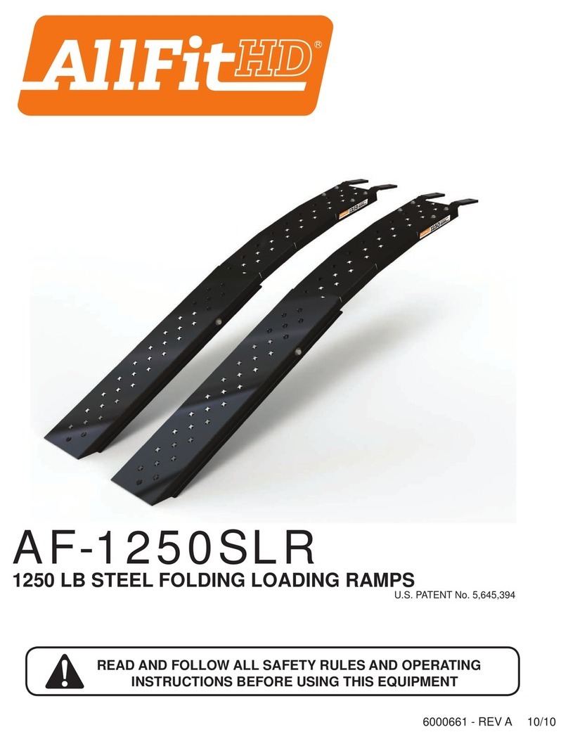
Ohio Steel AllFitHD AF-1250SLR User manual

Ohio Steel 1084D User manual

Ohio Steel

Ohio Steel 1084D User manual

Popular Automobile Accessories manuals by other brands

Magneti Marelli AC161 Installation instruction

Magneti Marelli

Magneti Marelli AC161 Installation instruction

FDI uEZ GUI Start here

FDI

FDI uEZ GUI Start here

JCROffroad JT Install instructions

JCROffroad

JCROffroad JT Install instructions

Rostra VOXXElectronics 250-1930 owner's guide

Rostra

Rostra VOXXElectronics 250-1930 owner's guide

TOP VEHICLE TECH GR3FORD5 installation manual

TOP VEHICLE TECH

TOP VEHICLE TECH GR3FORD5 installation manual

Safe Fleet PRIME DESIGN AR-2000-BLK manual

Safe Fleet

Safe Fleet PRIME DESIGN AR-2000-BLK manual

Skoda Fabia Combi 5J Fitting instructions

Skoda

Skoda Fabia Combi 5J Fitting instructions

Camcar 40077 Al Mounting instructions

Camcar

Camcar 40077 Al Mounting instructions

Camcar 40089 AL Mounting instructions

Camcar

Camcar 40089 AL Mounting instructions

Impac Tradesman 2000 installation manual

Impac

Impac Tradesman 2000 installation manual

DVB OFFROAD BRSB-01 installation manual

DVB

DVB OFFROAD BRSB-01 installation manual

Safari Snorkel SS385HF installation guide

Safari Snorkel

Safari Snorkel SS385HF installation guide

ULTIMATE SPEED 279746 Assembly and Safety Advice

ULTIMATE SPEED

ULTIMATE SPEED 279746 Assembly and Safety Advice

SSV Works DF-F65 manual

SSV Works

SSV Works DF-F65 manual

ULTIMATE SPEED CARBON Assembly and Safety Advice

ULTIMATE SPEED

ULTIMATE SPEED CARBON Assembly and Safety Advice

Witter F174 Fitting instructions

Witter

Witter F174 Fitting instructions

WeatherTech No-Drill installation instructions

WeatherTech

WeatherTech No-Drill installation instructions

TAUBENREUTHER 1-336050 Installation instruction

TAUBENREUTHER

TAUBENREUTHER 1-336050 Installation instruction

manuals.online logo
manuals.online logoBrands
  • About & Mission
  • Contact us
  • Privacy Policy
  • Terms and Conditions

Copyright 2025 Manuals.Online. All Rights Reserved.

14
TELESCOPING ALUMINUM
ATV LOADING RAMP
Model 1084TR
625 pound capacity - single.•
1,250 pound capacity - double.•
Compact Storage.•
Assembly required.•
One person loading.•
WARNINGS
The loading ramp surfaces are sharp. Always wear proper clothing and use care when•
handling the loading ramps. (Gloves are strongly recommended).
Read and understand all safety and operating instructions before using the loading ramp.•
Never allow anyone unfamiliar with these instructions to use the loading ramps.
Read and understand all safety and operating instructions provided by the manufacturer•
of the equipment the loading ramp will be used with.•
Extreme caution should always be used while loading and unloading your equipment.•
Do not exceed the rated capacity of the loading ramp.•
Do not exceed the rated capacity of the loading surface (i.e. tailgate). If unknown, contact•
the manufacturer to find the maximum load capacity.
Never stand in the path of equipment being loaded, and keep all bystanders and children•
away from loading ramps.
This ramp must be only used for loading and unloading to and from a level and stable•
surface.
Use caution when using ramp in icy or wet conditions. The ramp surface may become•
slippery.
Do not use this loading ramp to load live animals.•
Do not use loading ramps as a bridge, scaffolding, or any other use for which it is not•
intended or designed.
If ramp is bowing while loading or unloading your equipment, which indicates an overload•
condition, remove the equipment immediately.
Do not attempt to load or unload any power equipment with its motor running.•
Failure to follow these warnings may result in property damage and/or serious bodily injury.•
Repair Parts
When ordering repair parts always give the following information,
PRODUCT NAME, MODEL NUMBER, PART NUMBER, and PART DESCRIPTION.
For missing parts or questions
Call 1-800-652-2321
Ohio Steel Industries
Columbus, OH 43224 U.S.A.
Visit our website: www.ohiosteel.com
LIMITED ONE-YEAR WARRANTY
If this product fails due to a defect in material or workmanship within one year from the date
of purchase, Ohio Steel will at its option repair or replace it free of charge. Proof of
purchase required for all warranty claims.
This warranty does not cover:
Repairs necessary because of operator abuse or negligence.•
Equipment used for commercial or rental purposes.•
Contact Ohio Steel to arrange for product repair, or return this product to place of purchase for
replacement.
This warranty gives you specific legal rights, and you may also have other rights which vary
from state to state. This Warranty applies only while this product is in use in the United States.
6
7
15
7
8
213
1
910
5
12
4
3
REV-B
17
Manufactured under U.S. Patent No. 5,645,394
REF. NO
.
PART NO. AMT. DESCRIPTION
R
EF. NO
.
PART NO. AMT. DESCRIPTION
1 84TR-01 1 RAMP TOP 10 STDWF375USS 4 3/8" FLAT WASHER
2 84TR-02 1 RAMP BOTTOM 12 STDNK370 4 3/8"-16 KEPS NUT
3 LR-03 2 SUPPORT BAR 13 84TR-13 1 SNAP BUTTON (A-190S)
4 LR-04 2 CLEVIS PIN 14 LR-14 1 BUNGEE W/S-HOOK
5 LR-05 2 SUPPORT BAR PADS 15 84TR-15 1 NYLON HANDLE
6 STDBH2500375 2 1/4"-20 X 3/8" BOLT 16 84TR-16 1 MANUAL - NOT SHOWN
7 STDWF250USS 4 1/4" FLAT WASHER 17 84TR-17 1 HARDWARE BAG - NOT SHOWN
8 84TR-08 2 1/4"-20 T-NUT 18 84TR-18 1 WARNING DECAL - ON RAMP
9 STDBH3750750 4 3/8"-16 X3/4" BOLT
X
POSITION A
POSITION B
POSITION C
POSITION D
SAFETY
Be sure to read and follow all safety instructions and warnings. Failure to follow these•
instructions may result in damage to the product and/or serious personal injury.
Danger of serious personal injury exsists. Serious personal injury can occur when using a•
loading ramp.
Never attempt to ride any vehicle up or down the loading ramp.•
Look for a wall or a depression to reduce the loading angle, the lower the ramp angle the•
easier the loading of the vehicle will be.
Park the vehicle on flat, firm, grassy terrain.•
Set the emergency brake and chock the tires of the loading vehicle to prevent any•
movement while loading and unloading the equipment.
Center loading ramp on the loading surface with support bars on top of the loading surface.•
Make sure ramps are aligned at the proper distance apart so that the tires of the equipment•
being loaded are centered on the ramp.
To prevent kick back, always attach bungee straps between the bumper of the truck and the•
center of loading ramp, stretching strap at least 5 or 6 inches.
Roll or winch equipment up or down the ramp.•
Before each use, always check for any worn, loose, or damaged parts on the loading ramp.•
If any damage is present, DO NOT USE THE RAMP.
Periodically check the fasteners to make sure they are still tight and in place.•
Keep ramp surface clean by occasionally cleaning with water and any mild detergent.•
Do not add to or try to modify the loading ramp in any way. Any modifications will void any•
warranties as well as affect the structural integrity of the ramp itself.
We suggest that you drill 7/16" diameter
holes through the support bars (3) into
the tail gate or truck bed so that the pins
can be inserted as a safety device in
holding ramps in place. To prevent kick
back of the loading ramp, always attach
bungee strap to bumper of truck and
center of ramp stretching 5" to 6". Align
individual ramps to correctly correspond
to your ATV's track. Always remove key,
turn fuel off, and set parking brake after
loading ATV.
OPERATION
7/16" wrench and/or socket
9/16" wrench and/or socket
Large blade screwdriver
TOOLS SUGGESTED FOR
ASSEMBLY
RECOMMENDED SAFE OPERATING
HEIGHTS, DO NOT EXCEED "X".
POSITION A,
DO NOT EXCEED 22"
POSITION B,
DO NOT EXCEED 25"
POSITION C,
DO NOT EXCEED 29"
POSITION D,
DO NOT EXCEED 33"
Attach support bars (3) to ramp top (1) with four 3/8" x 1" bolts (9), flat•
washers (10), and keps nuts (12).
Slide support bar pads (5) onto bars as shown.•
Apply a little soapy water inside support bar
pad, this allows the pad to slide
onto the bar easier.
Compress and insert snap button (13) into•
rail of ramp top as shown and slide into
side hole of ramp top.
Ramp Top Assembly
Adding the Carrying Strap.
Insert tee nut (8) into the carrying•
strap hole in bottomramp section
as shown.
Place flat washer (7) over tee nut,•
place carrying strap (15)over
tee nut, add another flat
washer (7) and secure
with hex bolt (6).
Connecting the Two Ramp Halves
While pushing snap button, insert top ramp assembly into•
bottom ramp half until snap engages into
side hole in ramp bottom.
Push snap button in while holding ramp•
top to adjust ramp to desired length.
Note: Make sure snap button•
engages into hole before
attempting to use ramp.
5
3
12
910
1
13
8
15 7
67
Tee nut
properly inserted.
Push snap button
in while assembling
ramp halves.