Pintek DP-15K User manual

15KVp-p / 75MHz
INSTRUCTION MANUAL
使 用 說 明 書
HIGH VOLTAGE DIFFERENTIAL PROBE
差 動 測 試 棒
DP-15K

1

2
TABLEOFCONTENTS
FEATURES--------------------------------------------------------------- 5
SPECIFICATIONS-------------------------------------------------------- 5
PANEL DESCRIPTION------------------------------------------------------6
OPERATING ENVIRONMENTAL CONDITIONS----------------7
OPERATING PROCEDURE------------------------------------------7
EXT. POWER SOURMAINTENANCE-----------------------------------9
CLEANING------------------------------------------------------------------------9
WARRANTY--------------------------------------------------------------------9
REPAIR-------------------------------------------------------------------------9
DERATING CURVE-----------------------------------------------------10
目 次
簡述-----------------------------------------------------------------14
規格--------------------------------------------------------------14
測試棒面板說明-------------------------------------------------------15
操作環境及狀況-------------------------------------------------------------16
操作程序----------------------------------------------------------------------16
外接電源------------------------------------------------------------------------18
清潔----------------------------------------------------------------------------18
保固-------------------------------------------------------------------------------18
維修-------------------------------------------------------------------------------18
高頻耐電壓曲線參考圖----------------------------------------19

3

4
DP-15K
HIGH VOLTAGE DIFFERENTIAL PROBE

5
Differential Voltage Probe,
Read the instructions before using the instrument:
1.Must acquire a differential voltage probe & get the best service from
instrument.
2.Read carefully the USER MANUAL.
3.Respect the safety precautions.
SAFETY PRECAUTIONS
Warning, Risk of Electric Shock,
Respect the max input voltages.
1.Max differential voltage: 15KV (DC + AC peak) or 5.5KV RMS
2.Max voltage between each input terminal and ground:7.5KV RMS
Do not use the probe in damp environment or where there is
risk of explosion.
Do not use the probe with its case open.
Disconnect the inputs and outputs of the probe before
opening the case.
TO ORDER Differential Voltage Probe and Accessories:
An Insulated BNC/BNC lead and two Ф4 mm, length 3 inches (BP-250).
Supplied a Adapter preset 5 V / 2 A, (AC: 100 ~ 240 V) ASW-01
2 x high voltage IC clips (BP-266N).
2 x Banana to Banana high voltage plug (BP-366A).
2 x Alligator plug (BP-276N).
Instruction Manual.

6
FEATURES:
The DP-15K differential voltage probe provides a safety means of
measuring floating potentials for all models of oscilloscopes incomplete
safety.
It converts the high differential voltage (≦15 KV peak) into a low voltage
(≦8.0 V) with reference to the earth for display on the oscilloscopes.
The MAX. bandwidth is 75MHz, is suitable for big power testing and
research using.
The BNC output is designed to operate on an input with an impedance
of 1 MΩ. It is 2 times of the 50 Ω.
DP-15K is able to connect to DMM to observe directly. It is able to get
more accurate testing real value. (Oscilloscope accuracy is 3%, DMM
is about 10 times accuracy).
DP-15K is a design for high sensitivity module and high dynamic range.
Attenuation x 100, x 1000 is multiple of 10, which is easy for calculation
without mistake. Maximum voltage is 15KVp-p. It is a model designed
for ultra high voltage.
SPECIFICATIONS:
(1) Bandwidth:
DC - to 75 MHz (-3 dB) for x 100
DC - to 20 MHz (for attenuation x 1000)
(2) Attenuation: x 100, or x 1000
(3) Accuracy: ±2%
(4) Voltage Input Ranges (DC + AC peak to peak):
≦1.5 KVp-p for x 100, (i.e about 550 V RMS or ±750 V DC)
≦15 KVp-p for x 1000, (i.e about 5.5 KV RMS or ±7.5 KV DC)
(5) Permitted Max Input Voltage
Max differential voltage: 15 KV (DC + AC peak to peak)
Max voltage between each input terminal and ground: 7.5 KV RMS
7
(6) Input Impedance:
Differential: 54.4 MΩ// 1.5 pF
Between terminals and ground: 27.2 MΩ// 3 pF
(7) Output: ≦±8.0 V
(8) Output Impedance: 50 Ω
(9) Rise Time: 4.7 ns for x 100; 17.5 ns for x 1000
(10) Rejection Rate on Common Mode:
60 Hz: >80 dB ; 100 Hz: >60 dB ; 1 MHz: >50 dB
(11) Power Supply:
External 5 ~ 9 V DC power supply.
(12) Consumption: 200 mA about (5 ~ 9 V DC)
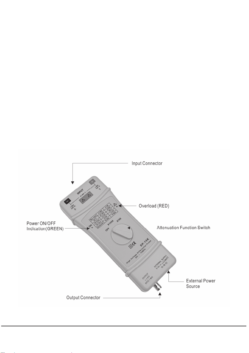
PANEL DESCRIPTION:

8
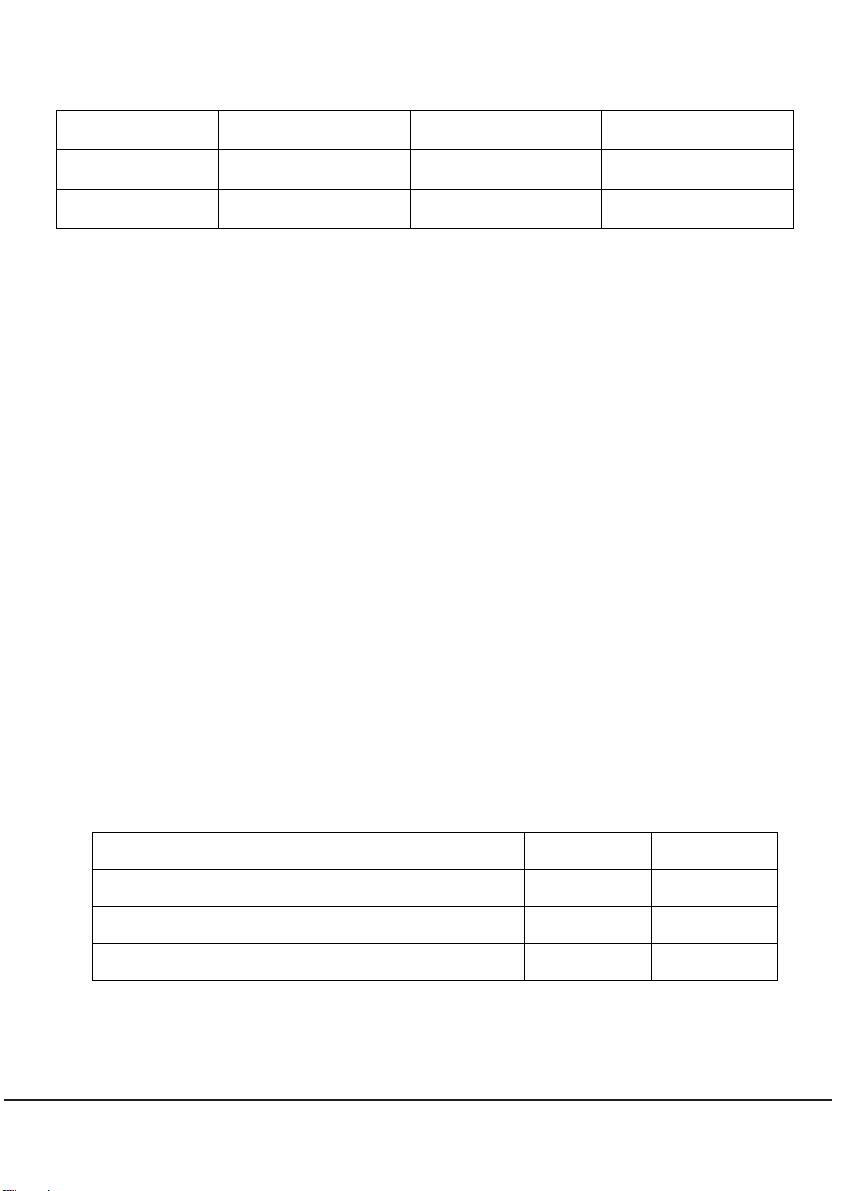
OPERATING ENVIRONMENTAL CONDITIONS:
Reference Use Storage
Temperature +20°C …+30°C 0°C …+50°C -30°C …+70°C
Relative
Humidity ≦70 % RH 10 % … 85 % RH 10 % …90 % RH
(1) Dimensions and Weight:
220 x 85 x 30 mm; 350 g
(2) Electrical Safety to IEC 1010-1:
Dual Insulation
Installation Category III
Degree of Pollution 2
Rated Voltage or Max Live-Earth: 7.5 KV RMS
(3) CE Mark:
Conforms to EN 50081-1 and 50082-1 standards
OPERATING PROCEDURE:
Connect to leads to the input and place the wire-grip on the circuit to be
tested.
Connect the probe to the oscilloscope with the insulated BNC/BNC
lead.
Adjust the vertical zero adjustment of the oscilloscope if necessary.
Select the attenuation ratio* and the vertical deviation of the
oscilloscope in accordance with the conversion table below.
NB: The POWER light must come on.
The conversion table gives the real vertical deviation.
Attenuation X 1000 X 100
MAX Voltage Input Range(DC+AC Peak) 15 KV 1.5 KV
DC MAX INPUT ±7.5 KV ±750 V
AC RMS MAX INPUT 5.5 KV 550 V

9
Vertical Deviation
on the Oscilloscope
in V/div
Real Deviation In V/div
x 1000 Range x 100 Range
1 1000 100
0.5 500 50
0.2 200 20
0.1 100 10
50 m 50 5
20 m 20 2
10 m 10 1
5 m 5 0.5
2 m 2 0.2
[NOTE]
The real vertical deviation in V/div is equal to the attenuation factor
multiplied by the range of vertical deviation selected on the
oscilloscope. It will be doubled in the case of use of a 50 Ωload.
Example:
With the probe on factor x100, the oscilloscope on 0.5 V/div, the real
vertical deviation is 100 x 0.5 = 50 V/div.
With a 50Ωload on the input of the oscilloscope the deviation becomes
100 V/div.

10
EXT. POWER SOURCE:
Power consumption of the probe is about 200mA, thus it not suit for
battery, please use the accessory adapter only.
If there are any damage on the adaptor, please contact us and use the
adaptor supply by us only. If the input power over 12V DC will caused
to the probe hard damage.
MAINTENANCE:
For maintenance, only use specified spare parts.
The manufacturer can not be held responsible for any accident arising
following a repair made other than its after sales service or approved
repairers.
CLEANING:
This probe does not require any particular cleaning. If necessary, clean the
case with a cloth slightly moistened with soapy water.
WARRANTY:
Unless notified to the contrary, our instruments are guaranteed against any
manufacturing defect or material defect. They do not bear the specification
known as the safety specification. Our guarantee, which may not under any
circumstances exceed the amount of the invoiced price, goes no further
than the repair of our faulty equipment, carriage paid to our workshops.
REPAIR:
Maintenance, repairs under or out of guarantee. Please return to product to
your distributor.

11
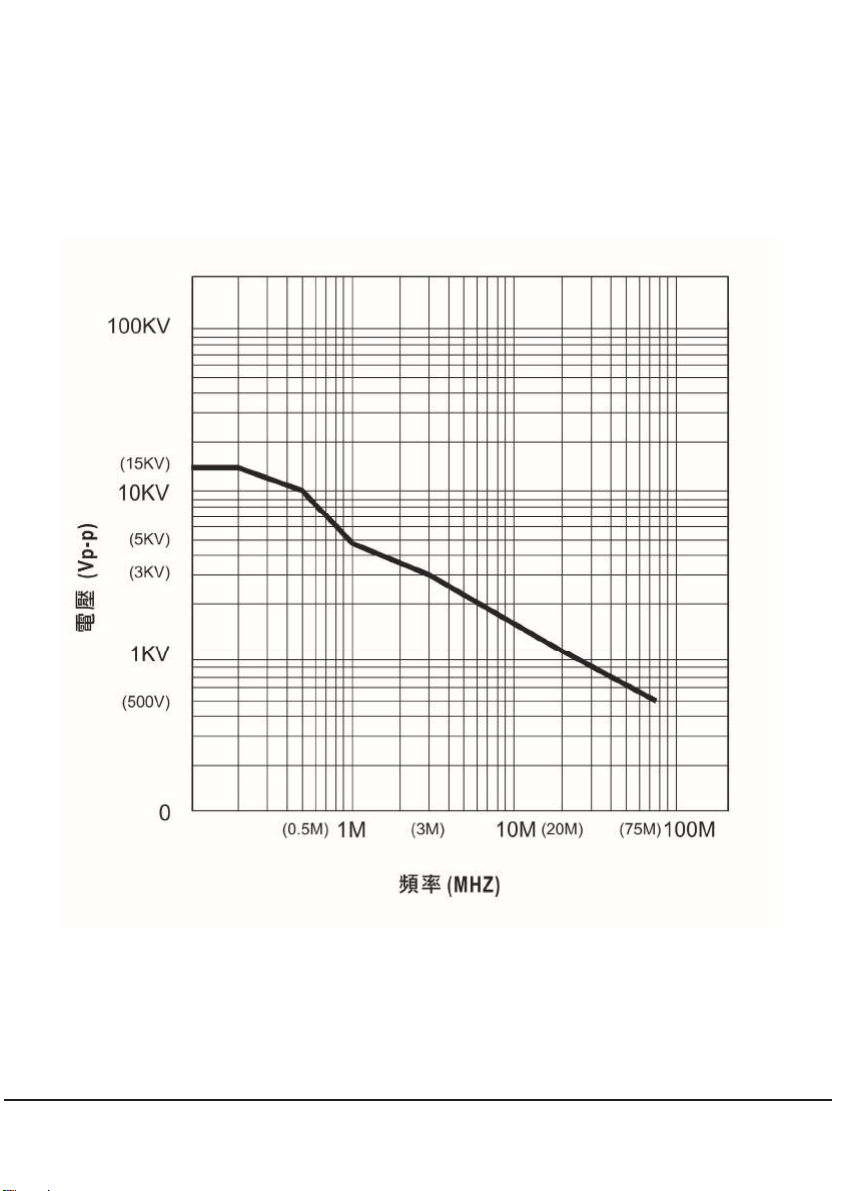
DERATING CURVE:
The derating curve of the absolute maximum input voltage in common
mode is show as follows:
100 KHz /15 KVp-p, 500 KHz / 10 KVp-p, 1 MHz / 5 KVp-p, 3 MHz / 3 KVp-p,
20 MHz /1 KVp-p, 75 MHz / 500 Vp-p
※Specification is subject to change as required by our company. Our
website information shall be updated immediately if any change is done.
Instruction booklet can be downloaded on our website. (Attached is the
Ver. 01 of the instruction booklet).

12
DP-15K
差動測試棒

13
使用前請詳細閱讀使用說明:
1. 請先獲得一支差動測試棒
2. 從使用說明取得最佳維修及服務
3. 請詳讀使用者操作手冊
4. 請注意安全注意事項
安全注意事項:
請小心注意觸電!
請注意最高輸入電壓!
最高差動電壓: 15 KV (DC + AC peak) 或5.5 KV RMS
輸入端及接地端間的最大差動電壓: 7.5 KV RMS
請勿使用此產品在潮濕的環境下或有易爆的風險下操作!
請勿使用此產品當此產品的盒蓋被打開!
當打開此產品的盒蓋時請將輸出及輸入端切斷!
訂購差動測試棒時內含:
雙端 BNC 接頭的測試纜線,長度 3英呎(BP-250)
一個 5V DC 轉換器, ASW-01 (AC 100 ~ 240 V 適用) DC 5 V/ 2 A
一對高電壓專用的 IC 夾(BP-266N)
一對指定規格的雙端香蕉插頭高電壓傳輸線(BP-366A)
一對高電壓專用的鱷魚夾(BP-276N)
使用說明書

14
簡述:
DP-15K 差動測試棒提供一個安全的絕緣儀器給所有的示波器使用, 它
可以轉換由高輸入的差動電壓(≦15 KV PEAK) 進入一個低電壓(≦8
V), 並且顯示波形在示波器上, 使用頻率高達 75 MHz 非常適合大電力測
試、研發使用。
差動測試棒輸出標示是設計在操作示波器 1 MΩ的輸入阻抗的相對衰減
量, 當使用 50 Ω匹配器時衰減量剛好為 2倍量。
DP-15K 也建議直接使用數字電錶觀測, 可以獲得更準確的實測值(示波
器精確度為 3%, 數字電錶大約精準 10 倍)。
DP-15K 為一高靈敏度設計, 動態範圍之大前所未見, 衰減器 x 100, x
1000 皆為 10 進位以方便使用者計算, 不容易出錯, 最高電壓達到 15
KVp-p, 為一超高電壓設計的機種。
規格:
(1) 頻寬:
DC - 75 MHz (-3 dB) x 100 檔
DC - 20 MHz (衰減 x 1000 檔)
(2) 衰減:x 100, 或x 1000
(3) 精確度:±2%
(4) 輸入電壓範圍 (DC + AC PEAK TO PEAK)
≦1.5 KVp-p for x 100, (約550 V RMS 或 ±750 V DC)
≦15 KVp-p for x 1000, (約5.5 KV RMS 或±7.5 KV DC)
(5) 允許最高輸入電壓:
最高差動電壓: 15 KV (DC + AC PEAK TO PEAK)
輸入端及接地端間最高電壓: 7.5 KV RMS
(6) 輸入阻抗:
差動: 54.4 MΩ// 1.5 pF
單端到接地端間的輸入阻抗: 27.2 MΩ// 3 pF
(7) 輸出電壓: ≦±8 V

15
(8) 輸出阻抗:50 Ω
(9) 上升時間:
4.7 ns for x 100
17.5 ns for x 1000
(10) 雜訊抑制率:
60 Hz: > 80 dB ; 100 Hz: > 60 dB ; 1 MHz: > 50 dB
(11) 電源:
指定外接 5 ~ 9 V DC 電源(必須使用本公司指定品)
(12) 耗電:最大耗電量約 200 mA/5 ~ 9 V DC
測試棒面板說明:
16
操作環境及狀況:
一般狀態 使用操作中 儲存
溫度+20°C …+30°C 0°C …+50°C -30°C …+70°C
濕度≦70 % RH 10 % … 85 % RH 10 % … 90 % RH
(1) 尺寸及重量::
220 x 85 x 30 mm; 350 g
(2) 電子安全規範 IEC 1010-1:
雙絕緣
安裝類目 III
污染程度 2
相關電壓或最大接地: 7.5 KV RMS
CE: EN50081-1 及50082-1
操作環境及狀況:
將附件 BP-366A 與BP-266N (或BP-276N) 接起來後插入 DP-15K 的
輸入端, 並將 BP-266N (或BP-276N) 與測量物接觸。
將BP-250 與DP-15K 的輸出端連接, 並與示波器連結。
如有需要先調整示波器上的垂直開關。
將示波器上的衰減率及垂直開關調整到一致的位置, 如下表。
注意: 電源必須打開。
衰減x 1000 x 100
最大輸入電壓 (DC+AC Peak) 15 KV 1.5 KV
DC 最大輸入 ±7.5 KV ±750 V
AC RMS 最大輸入 5.5 KV 550 V

17
示波器上的
垂直偏向(V/DIV)
換算實際偏向(V/DIV)
x 1000 檔x 100 檔
1 1000 100
0.5 500 50
0.2 200 20
0.1 100 10
50 m 50 5
20 m 20 2
10 m 10 1
5 m 5 0.5
2 m 2 0.2
[注意]
實際的垂直偏向是等於衰減乘上示波器上所選擇的垂直偏向. 如果另外
使用 50Ω負載端子時,實際電壓值剛好是 2倍量。
例如:
測試棒是 x 100, 示波器的垂直偏向在 0.5, 其實際的垂直偏向為:
100 x 0.5 = 50 V/div
示波器輸入的負載是 50 Ω, 偏向就為 100 V/div

18
外接電源:
本產品因耗電量高達 200 mA, 因此指定使用本公司提供的電轉接器。
請勿使用非本公司指定品, 若因此造成任何損毀, 本公司概不負責。
維護:
保養此產品時請使用原廠指定的工具, 原廠將不負任何責任由其他不被認可
的維修人員所做的維修。
清潔:
此產品不需要任何特定的清潔, 如有需要, 請用輕軟乾淨的布沾上微量的清
潔液輕輕的在產品外觀擦拭。
保固:
除了在人為上的特意損壞, 本產品是受保固並可以維修的, 並不包含在安全
規範的責任。
保固是以不超出發票上的金額, 零件的更換及運送的費用。
保固是僅在正常操作下而造成的損壞, 並不包含任何刻意的損壞, 操作上的
錯誤, 機械上的操作不當, 保養不當, 負載或過壓。
原廠的保固僅包含有限的單純更換損壞的零件, 使用者將不可歸據直接或間
接的責任在原廠。
原廠的保固是賣出後的 12 個月內, 如有任意的非原廠的維修或更換零件, 原
廠保固將自然取消。
維修:
有任何的維修, 保養或更換零件是在保固以外, 請將產品退回原廠維修。
19
高頻耐電壓曲線參考圖:
(在共同模式下最大輸出電壓與頻率的相對應曲線參考圖)
100 KHz /15 KVp-p, 500 KHz / 10 KVp-p, 1 MHz / 5 KVp-p, 3 MHz / 3 KVp-p,
20 MHz /1 KVp-p, 75 MHz / 500 Vp-p
[註] 本公司保留變更規格的權利, 若有規格版別之更動將直接更新網
站資料; 歡迎上網下載說明書!(隨機 Ver.02 版)
Table of contents
Other Pintek Measuring Instrument manuals

Pintek
Pintek DP-30K User manual

Pintek
Pintek HVP-10R User manual

Pintek
Pintek HVP-40 User manual

Pintek
Pintek PA-629 User manual

Pintek
Pintek DP-16VF User manual

Pintek
Pintek PA-699 User manual

Pintek
Pintek PA-677 User manual

Pintek
Pintek HVP-18HF User manual

Pintek
Pintek PA-659 User manual

Pintek
Pintek HVP-40M User manual


Popular Measuring Instrument manuals by other brands

Buckleys
Buckleys 6004-0093 operating instructions

Electro Industries
Electro Industries Shark 100 quick start guide

Endress+Hauser
Endress+Hauser SpectraSensors J22 TDLAS operating instructions

MANN+HUMMEL
MANN+HUMMEL SPB 358 manual

Bacharach
Bacharach Ultra MAC 2000 Series Catalogue

Sonel
Sonel PQM-700 operating manual


