manuals.online logo
Brands
  1. Home
  2. •
  3. Brands
  4. •
  5. OHTAKE
  6. •
  7. Cash Counter
  8. •
  9. OHTAKE NEX-PLC User manual

OHTAKE NEX-PLC User manual

p. 1
Manual for External Batch/Screw Counter (NEX-PLC) for Screw Feeder FME-36
1.Summary
This counter can interface with a screw feeder FME-36 by setting the number of batches/screws,
to be fed, directly into this device or else from a PLC.
2.Specifications
2.1Product specifications
Power supply
AC adapter DC24V 1.9A (AC100V~240V)
Operating environment
Input 8 points / Output 8 points I/O terminal
Dimensions
155mm×113mm×44mm
2.2Parts description
FIG1. Machine features
①[DC24V] :Power supply connector (Marushin Electric Mfg:MJ-20)
Input terminal for power supply: DC24V.
Synchronized ON/OFF power with the FM36 screw feeder connector.
24V and GND on the terminal block are Output terminals.
②[FM36] :Interface connector (Tajimi Electronics:PRC05-P8F)
Cable connection to screw feeder.
③[POWER] :LED
Light indicates when power is ON.
④[L/R-SW] :Changing switch
Choose between Local Mode or Remote Mode.
Choose the mode when the power is OFF.
Local Mode: feeds the number of screws set directly on the counter.
Remote Mode: feeds the set number of screws set using an external signal .
①
②
③
④
⑦
⑥
⑤
⑨
⑧
⑩
p. 2
⑤[Local] :LED
Light indicates Local Mode.
⑥[Remote] :LED
Light indicates Remote Mode.
⑦[INPUT]&[OUTPUT] :Input & Output signal terminal block(Omron:XW4E-10B1-V1)
Can be used on Remote Mode with an external device such as a PLC.
⑧[Counter] :Indicator
Displays the number of screws the feeder is to supply.
Each mode has a different display. Confirm with the respective descriptions.
⑨[Complete] :LED
Light indicates when feeding the set number of screws is completed.
⑩[Overload] :LED
Lights indicates when the screw feeder is overloaded and stopped.
2.3Input & Output signal terminal block
FIG 2. Input & Output signal terminal block
・[INPUT] Terminal specifications
[24V]: DC24V Output terminal
[IN1]: Input terminal for starting signal of screw feeding
[IN2]: 1st bit input terminal
[IN3]: 2nd bit Input terminal
[IN4]: 3rd bit Input terminal
[IN5]: 4th bit Input terminal
[IN6]: 5th bit Input terminal
[IN7]: 6th bit input terminal
[IN8]: 7th bit Input terminal
[GND]: Ground (0V Output) terminal for [24V]
Confirm with Appendix 1 on how to set the number of screws to be
fed as well as IN2~8 signals.
p. 3
・[OUTPUT] Terminal Specifications
[24V]: DC24V Output terminal
[OUT1]: Output terminal for Request signal of Starting signal for screw feeding.
※2 seconds after screw extraction, the output signal changes.
[OUT2]: Output terminal signaling the set number of screws are to
be extracted.
※For at least 2 sec., the output signal indicates Low output.
[OUT3]: Output terminal signaling the set number of screws are to be extracted.
[OUT4]: Output terminal for the 1st request of the starting signal after
the power is turned ON.
[OUT5]: Output terminal signaling the screw feeding operation.
[OUT6]: Output terminal for the 2nd or later request of the starting signal
after the power is turned ON.
[OUT7]: Output terminal for the overload and stopped signal.
[OUT8]: Output terminal for the extracting error and stopped signal.
[GND]: Ground (0V Output) terminal for [24V]
・Internal circuits
The internal circuits for both the INPUT and OUTPUT terminals
are described below in Figures 3 and 4.
In FIG 3 & 4, 24V and GND are [24V] and [GND] terminals.
[24V] and [GND] on INPUT and OUTPUT use their respective terminals.
FIG 3. [IN*] terminal FIG 4. [OUT*] terminal
IN * terminal
OUT * terminal
p. 4
3.Operations
3.1Local mode
・Operation sequences
When the set number of screws are extracted from the feeding site,
another set is delivered.
・Counter display and operation
On Local Mode, the counter displays as in Fig. 5.
FIG 5. Counter display on Local Mode
The right side of the display is the set number of screws to be fed.
When screw feeding starts,the number counts down.
The left side of the display is the cumulated number of times the set number
has been fed.
①Clearing the cumulated number counter.
Push Button B continuously until the number returns to "0000".
②Setting the number of screws to be fed.
When the cumulated number counter is at "0000", push Button B until
the tens digit is flashing, then every push of Button B changes the
tens digit number.
Push Button C until the single digit is flashing, then every push
of Button C changes the single digit number.
Set number
Cumulated number
Button A
Button B
Button C
p. 5
③Buzzer Volume Setting
Push Buttons A and C together until the display changes to "bu". (see Fig. 6)
Next push Button C only, to increase the volume from "00 ~03".
The displayed buzzer volume number is set and then the display will return
to normal.
FIG 6. Counter display when the buzzer volume is being set. (note "bu")
3.2Remote Mode
・Operation sequences
Refer to Timing Chart 1(page 9) for details of the operation.
Check the level of electricity, of the feeding operations, on OUT1 & 2.
Check the condition of the feeder on OUT3 & 8.
・Counter display and operation
Detecting a starting signal resets the counter to (00).
When screws are fed, the counter increases to the set number.
On Remote Mode, you can't clear the counter with the buttons, but can change
the buzzer volume.
FIG 7. Counter display on Remote Mode (note "Pc")
Buzzer volume setting
Feeding number
p. 6
4.Abnormal stop
4.1Irregular extracting stop
When screws are taken out before the set number of screws are fed, the machine decides
it's an irregular extracting, and it stops feeding.
On Remote Mode, after detecting an irregular extraction, OUT8 changes from HI output
to Low output.
Restarting operations are different for each mode.
・On Local Mode
When detecting the extraction site closed, the operation restarts and
the counter is reset to zero.
・On Remote Mode
After an irregular stop, if the extracting drawer is opened and closed,
the machine will restart.
Details are found on Timing Chart 2 (page 10).
4.2Overload stop
When the screw feeder indicates an Overload stop signal, the Overload LED lights up.
On Remote Mode, after the overload signal is detected, the terminal OUT7 changes from
HI to Low.
Details are found on Timing Chart 3 (page 11).
To restart, switch ON the power.
Shut the power OFF to resolve any problems such as reducing the amount of screws in
the hopper.
Then turn the power ON again to restart.
p. 7
5.Miscellaneous
5.1 Accessories
・AC adapter 1
・Manual book 1
・Screw feeder interface cable (approx 1m) 1
Note: Interface cable specifications
Connector: (Tajimi Electronics) PRC05-P8M 2
Cable connection : 8 wick straight
5.2 Connector specifications
Connector code
Maker
Model number
[DC24V]
Marushin Electric Mfg. Co., Ltd.
MJ-20
[FM36]
Tajimi Electronics Co., Ltd.
PRC05-P8F
[INPUT]
Omron
XW4E-10B1-V1
[OUTPUT]
Omron
XW4E-10B1-V1
Setting number
IN8 IN7 IN6 IN5 IN4 IN3 IN2
0HI HI HI HI HI HI HI
1HI HI HI HI HI HI Low
2HI HI HI HI HI Low HI
3HI HI HI HI HI Low Low
4HI HI HI HI Low HI HI
5HI HI HI HI Low HI Low
6HI HI HI HI Low Low HI
7HI HI HI HI Low Low Low
8HI HI HI Low HI HI HI
9HI HI HI Low HI HI Low
10 HI HI HI Low HI Low HI
11 HI HI HI Low HI Low Low
12 HI HI HI Low Low HI HI
13 HI HI HI Low Low HI Low
14 HI HI HI Low Low Low HI
15 HI HI HI Low Low Low Low
16 HI HI Low HI HI HI HI
17 HI HI Low HI HI HI Low
18 HI HI Low HI HI Low HI
19 HI HI Low HI HI Low Low
20 HI HI Low HI Low HI HI
21 HI HI Low HI Low HI Low
22 HI HI Low HI Low Low HI
23 HI HI Low HI Low Low Low
24 HI HI Low Low HI HI HI
25 HI HI Low Low HI HI Low
26 HI HI Low Low HI Low HI
27 HI HI Low Low HI Low Low
28 HI HI Low Low Low HI HI
29 HI HI Low Low Low HI Low
30 HI HI Low Low Low Low HI
31 HI HI Low Low Low Low Low
32 HI Low HI HI HI HI HI
33 HI Low HI HI HI HI Low
34 HI Low HI HI HI Low HI
35 HI Low HI HI HI Low Low
36 HI Low HI HI Low HI HI
37 HI Low HI HI Low HI Low
38 HI Low HI HI Low Low HI
39 HI Low HI HI Low Low Low
40 HI Low HI Low HI HI HI
41 HI Low HI Low HI HI Low
42 HI Low HI Low HI Low HI
43 HI Low HI Low HI Low Low
44 HI Low HI Low Low HI HI
45 HI Low HI Low Low HI Low
46 HI Low HI Low Low Low HI
47 HI Low HI Low Low Low Low
48 HI Low Low HI HI HI HI
49 HI Low Low HI HI HI Low
50 HI Low Low HI HI Low HI
51 HI Low Low HI HI Low Low
52 HI Low Low HI Low HI HI
53 HI Low Low HI Low HI Low
54 HI Low Low HI Low Low HI
55 HI Low Low HI Low Low Low
56 HI Low Low Low HI HI HI
57 HI Low Low Low HI HI Low
58 HI Low Low Low HI Low HI
59 HI Low Low Low HI Low Low
60 HI Low Low Low Low HI HI
61 HI Low Low Low Low HI Low
62 HI Low Low Low Low Low HI
63 HI Low Low Low Low Low Low
Appendix 1. Screw number settings and Input signals.
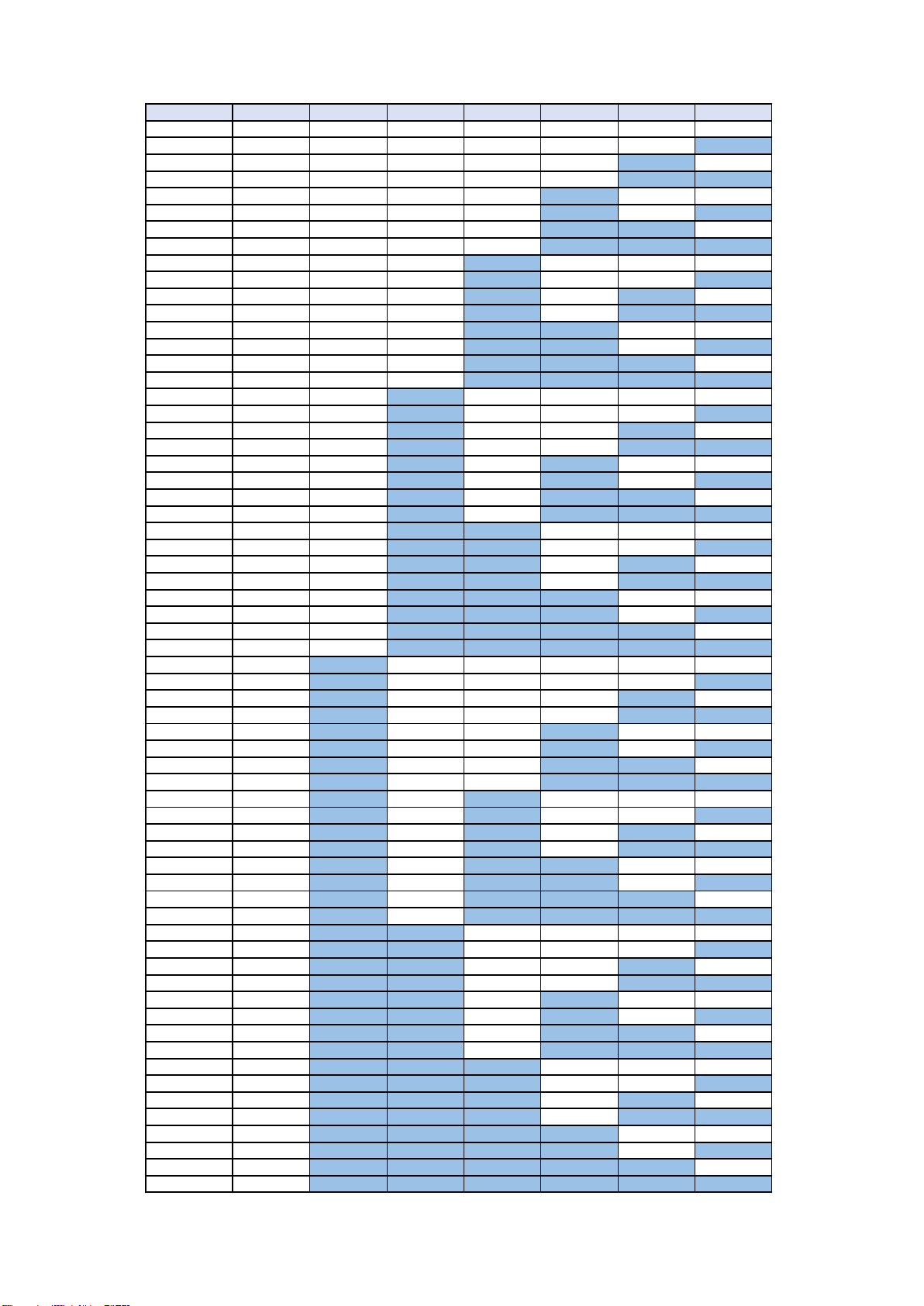
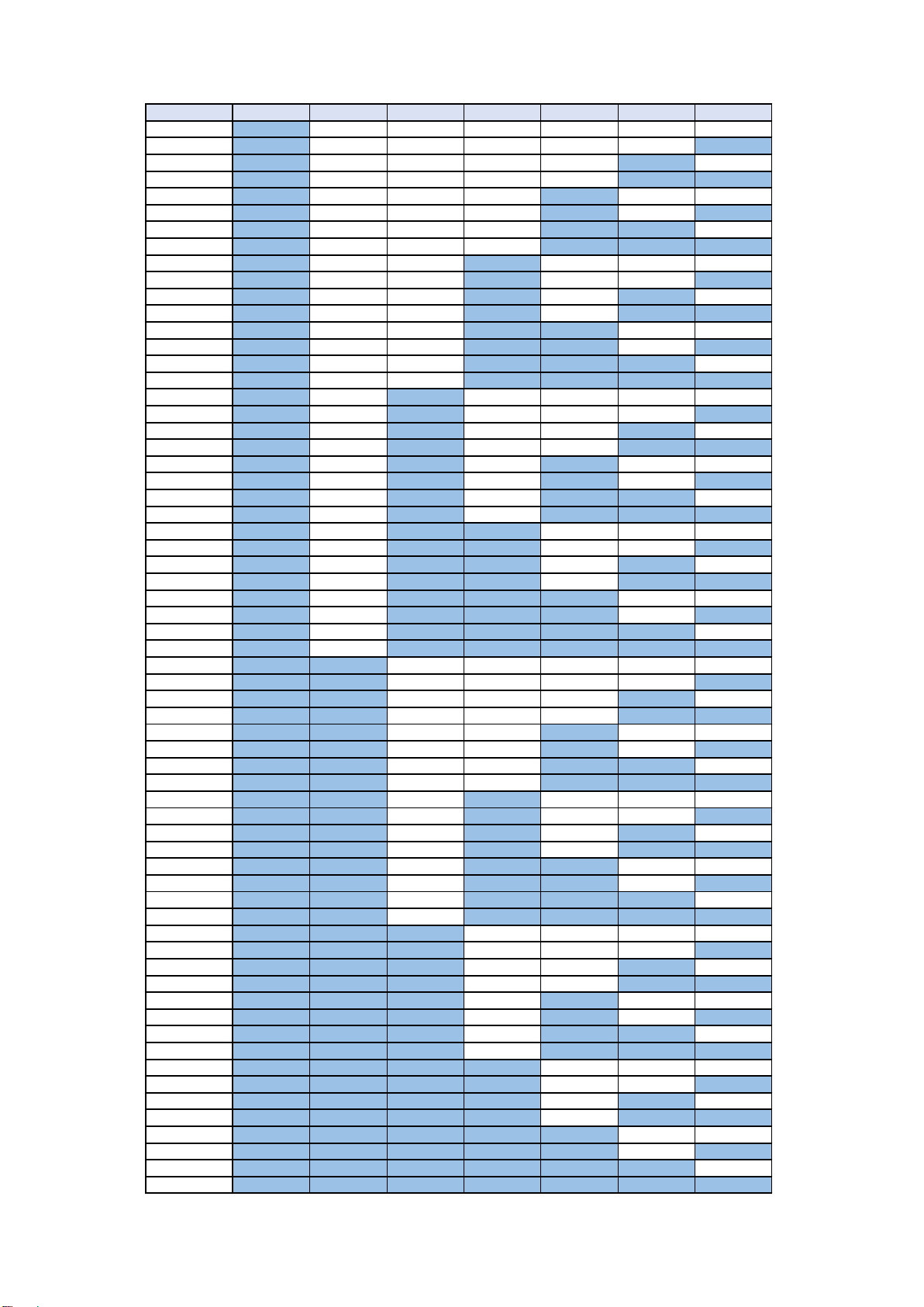
設定数 IN8 IN7 IN6 IN5 IN4 IN3 IN2
64 Low HI HI HI HI HI HI
65 Low HI HI HI HI HI Low
66 Low HI HI HI HI Low HI
67 Low HI HI HI HI Low Low
68 Low HI HI HI Low HI HI
69 Low HI HI HI Low HI Low
70 Low HI HI HI Low Low HI
71 Low HI HI HI Low Low Low
72 Low HI HI Low HI HI HI
73 Low HI HI Low HI HI Low
74 Low HI HI Low HI Low HI
75 Low HI HI Low HI Low Low
76 Low HI HI Low Low HI HI
77 Low HI HI Low Low HI Low
78 Low HI HI Low Low Low HI
79 Low HI HI Low Low Low Low
80 Low HI Low HI HI HI HI
81 Low HI Low HI HI HI Low
82 Low HI Low HI HI Low HI
83 Low HI Low HI HI Low Low
84 Low HI Low HI Low HI HI
85 Low HI Low HI Low HI Low
86 Low HI Low HI Low Low HI
87 Low HI Low HI Low Low Low
88 Low HI Low Low HI HI HI
89 Low HI Low Low HI HI Low
90 Low HI Low Low HI Low HI
91 Low HI Low Low HI Low Low
92 Low HI Low Low Low HI HI
93 Low HI Low Low Low HI Low
94 Low HI Low Low Low Low HI
95 Low HI Low Low Low Low Low
96 Low Low HI HI HI HI HI
97 Low Low HI HI HI HI Low
98 Low Low HI HI HI Low HI
99 Low Low HI HI HI Low Low
100 Low Low HI HI Low HI HI
101 Low Low HI HI Low HI Low
102 Low Low HI HI Low Low HI
103 Low Low HI HI Low Low Low
104 Low Low HI Low HI HI HI
105 Low Low HI Low HI HI Low
106 Low Low HI Low HI Low HI
107 Low Low HI Low HI Low Low
108 Low Low HI Low Low HI HI
109 Low Low HI Low Low HI Low
110 Low Low HI Low Low Low HI
111 Low Low HI Low Low Low Low
112 Low Low Low HI HI HI HI
113 Low Low Low HI HI HI Low
114 Low Low Low HI HI Low HI
115 Low Low Low HI HI Low Low
116 Low Low Low HI Low HI HI
117 Low Low Low HI Low HI Low
118 Low Low Low HI Low Low HI
119 Low Low Low HI Low Low Low
120 Low Low Low Low HI HI HI
121 Low Low Low Low HI HI Low
122 Low Low Low Low HI Low HI
123 Low Low Low Low HI Low Low
124 Low Low Low Low Low HI HI
125 Low Low Low Low Low HI Low
126 Low Low Low Low Low Low HI
127 Low Low Low Low Low Low Low
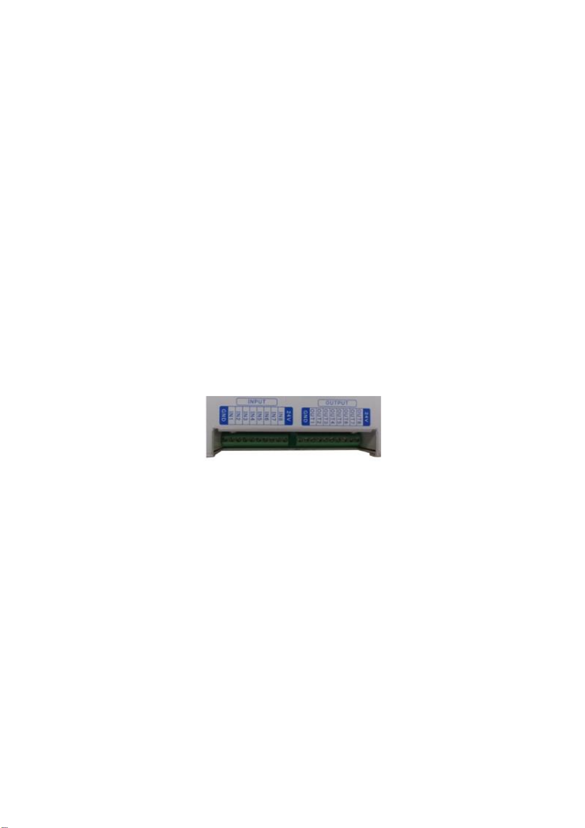
Appendix 2. Screw number settings and Input signals.
Timing Chart 1
Regular operation [OUTPUT/INPUT colored areas are Low output.]
LED POWER
Complete
OverLoad
OUTPUT OUT1 Request ※1 ※4 ※1 ※4
OUT2 Waiting to extract ※2 ※3
OUT3 Waiting to extract
OUT4 Request 1
OUT5 Mid-operation
OUT6 Request 2
OUT7 Overloaded
OUT8 Irregular extracting
INPUT IN1 Starting ※5 ※5
IN2 1st bit
IN3 2nd bit
IN4 3rd bit
IN5 4th bit
IN6 5th bit
IN7 6th bit
IN8 7th bit
External operation
Power ON
Extracting
Internal operation Setting screw number
Feeding motion
Count completed
Waiting
※1:2 seconds after detecting an input signal on IN1, OUT1 changes.
※2,3:OUT2 doesn't change at least for 2 seconds.
※4:2 seconds after OUT2 changed, OUT1 changes.
※5:When OUT1 is Low output, screw number (IN2~8) is set by switching H/L on IN1.
Flashing
Depends on setting
Timing Chart 2
Irregular extracting stop and restarting operation
 Screws taken out before the set number results in an irregular extracting and the machine stops.
 For restarting, do as follows.
 Reset the PLC to the original, desired operation.
 After detecting an irregular extracting, it remains in OUT1 and so must be reset to the original desired operation.
[OUTPUT/INPUT colored areas are Low output.]
LED POWER
Complete
OverLoad
OUTPUT OUT1 Request ※1 ※1 ※3
OUT2 Waiting to extract ※2
OUT3 Waiting to extract
OUT4 Request 1
OUT5 Mid-operation
OUT6 Request 2
OUT7 Overloaded
OUT8 Irregular extracting
INPUT IN1 Starting ※4 ※4
IN2 1st bit
IN3 2nd bit
IN4 3rd bit
IN5 4th bit
IN6 5th bit
IN7 6th bit
IN8 7th bit
External operation
Power ON
Extracting ※5 ※6
Internal operation Setting screw number
Feeding motion
Count completed
Waiting
※1:2 seconds after detecting an input signal on IN1, OUT1 changes.
※4:When OUT1 is Low output, screw number (IN2~8) is set by switching H/L on IN1
※5:Screws taken out in mid-feed results in an Irregular Extracting Stop.
※3:2 seconds after OUT2 changed, OUT1 changes.
※6:Restarting solves the irregular extracting stop.
Flashing
Flashing
※2:OUT2 doesn't change for at least 2 seconds.
Depends on setting
Timing Chart 3
Overload stop
[OUTPUT/INPUT colored areas are Low output.]
LED POWER
Complete
OverLoad
OUTPUT OUT1 Request
OUT2 Waiting to extract
OUT3 Waiting to extract
OUT4 Request 1
OUT5 Mid-operation
OUT6 Request 2
OUT7 Overloaded
OUT8 Irregular extracting
INPUT IN1 Starting ※4 ※5
IN2 1st bit
IN3 2nd bit
IN4 3rd bit
IN5 4th bit
IN6 5th bit
IN7 6th bit
IN8 7th bit
External operation
Power ON
Power OFF
Extracting
Internal operation Setting screw number
Feeding motion
Count completed
Waiting
 When the screw feeder is overloaded, the machine stops.
 Turn OFF the screw feeder to solve the overload problem, then turn the power ON again.
 Reset the PLC to the original, desired operation.
Flashing
Flashing
Flashing
Depends on setting
OHTAKE-ROOT KOGYO CO., LTD.
27 Kanegasaki, Hagisho
Ichinoseki, Iwate
021-0902 Japan
TEL: +0191-24-3144
FAX: +0191-24-3145
http://www.ohtake-root.co.jp
2021-03

Popular Cash Counter manuals by other brands

Amrotec S-200 Assembly instructions

Amrotec

Amrotec S-200 Assembly instructions

Royal Sovereign RBC-ES200 owner's manual

Royal Sovereign

Royal Sovereign RBC-ES200 owner's manual

F&F MB-LI-4 Hi manual

F&F

F&F MB-LI-4 Hi manual

Omron HJ-325 instruction manual

Omron

Omron HJ-325 instruction manual

Ribao BC-40 user manual

Ribao

Ribao BC-40 user manual

Amrotec MiB-9 Operator's Quick Handbook

Amrotec

Amrotec MiB-9 Operator's Quick Handbook

Triton RT2000 (X2) Quick reference guide

Triton

Triton RT2000 (X2) Quick reference guide

Baumer NE230 operating instructions

Baumer

Baumer NE230 operating instructions

Omron H7CX-Ax-N Series instruction manual

Omron

Omron H7CX-Ax-N Series instruction manual

Foster EPro Installation and operation

Foster

Foster EPro Installation and operation

red lion CUBC Series Technical bulletin

red lion

red lion CUBC Series Technical bulletin

red lion CUB7W Series Guideline

red lion

red lion CUB7W Series Guideline

KEPCO POSITROL PM2A3 Installation & operating instructions

KEPCO

KEPCO POSITROL PM2A3 Installation & operating instructions

red lion CUB4L Quick user guide

red lion

red lion CUB4L Quick user guide

Lighthouse Handheld 2016 operating manual

Lighthouse

Lighthouse Handheld 2016 operating manual

Trotec PC200 operating manual

Trotec

Trotec PC200 operating manual

Biogents BG instruction manual

Biogents

Biogents BG instruction manual

Lighthouse Remote 3014PN operating manual

Lighthouse

Lighthouse Remote 3014PN operating manual

manuals.online logo
manuals.online logoBrands
  • About & Mission
  • Contact us
  • Privacy Policy
  • Terms and Conditions

Copyright 2025 Manuals.Online. All Rights Reserved.