Capetti Elettronica WineCap WSD12-2DI User manual

WSD12-2DI
User Manual
Pulse counter

WSD12-2DI
User Manual
PAGE 2/13
WA0397_WSD12-2DI_User Manual_R06
www.capetti.it
General warnings.
•The following information must be read and understood before proceeding with the installation, commissioning and maintenance of
the devices described in this document.
•ATTENTION! Any omission or failure to follow these instructions scrupulously can cause danger.
•ATTENTION! Explosion hazard. In case of batteries substitution, make sure that the type is compatible and complies with the
specifications indicated by the manufacturer.
•In case of batteries substitution, DO NOT disconnect the flat cable which connect the electronic boards without removing batteries
before
•ALWAYS substitute all the batteries, also in case of one single battery exhausted.
•If the device is powered by a fixed network, make sure you have disconnected the power supply before carrying out any type of
intervention. Failure to comply with this indication can cause damage to people and/or property.
•Follow the manufacturer's suggested warm-up time (
time required to obtain a reliable measurement
) of the transducer.
•Follow the manufacturer's suggested electric wiring of the transducer to measure (
ground shields at a single point, cable length and
section
); voltage measures on distances exceed 15/20 meters are subjected to electromagnetic disturbances. 0÷25mA inputs have a
superior electromagnetic compatibility (
EMC
).
•Avoid passage in cavities with power or high voltage cables.
•The protection and safety measures and the warranty provided by the Manufacturer with the equipment may be compromised if it’s
used in a manner that does not comply with this user manual.
•This equipment complies with CE regulations.
•Modifications or tampering not expressly approved by the Manufacturer could void the user's authorization to operate the equipment.
•This equipment must be installed by qualified personnel and in accordance with national regulations and/or related local requirements.
•Make sure that the object is properly fixed to supports/infrastructures capable of withstanding this load. Make sure proper methods
and materials are used when fixing the equipment to a wall.
•Only personnel expressly authorized by the manufacturer can open the container. There are no user serviceable parts inside.

WSD12-2DI
User Manual
PAGE 3/13
WA0397_WSD12-2DI_User Manual_R06
www.capetti.it
1. Description.
The WSD12-2DI is a datalogger with two input channels to acquire pulses from clean contacts or open-collector, from energy meters, fluid
meters, etc. inputs, with storage functionality of samples acquired.
Counting is continuously performed on input channels and is partially considered on the configurable
sampling period. In case, counting can be set as aggregate and scalable.
Data are wireless transmitted and internally stored.
2. Sampling
In normal mode, the measure acquired is related to pulses counted in the programmed sampling
interval.
At the end of each interval, the counted value, multiplied by the energy weight, is transmitted to the
gateway,and internally saved.
After which, the counter is reset, and a new integration cycle starts.
In cumulative mode, count is maintained and is automatically updated to new value at each measure
interval.
Value can reach overflow; in case, counter resets and automatically starts again when reaches the
maximum value of 65,535 pulses.
Sampling time is selectable and adjustable by radio but is recommended to set a time and maintain
it fixed for the complete measure harvest to guarantee values and intervals homogeneity.
To perform an analysis in an established period, a summation of whole contributions coming from each interval is needed.
In normal mode, performing a graphical analysis of samples, is easily possible to compare higher impact pulse periods with lower impact ones,
obtaining the measure timing profile, locating peaks and lowest periods.
To obtain the total amount in a period, a sum of samples acquired in the period can be performed.
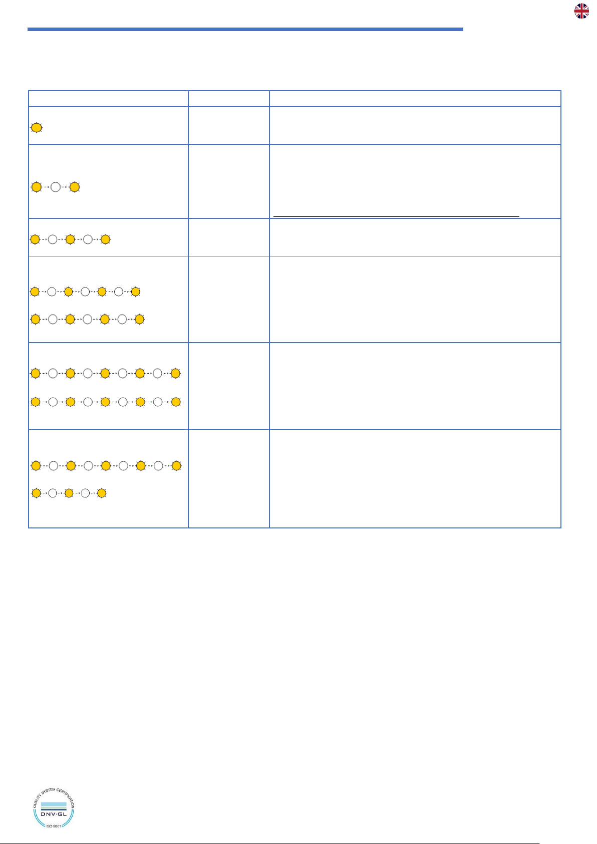
NOTE: if the gateway analog output is coupled to the datalogger’s meter channels, the expected output signal will be a tier where each level
represents the recorded energy in the previous period
A punctual evaluation of
weight
/
pulse
/
sampling interval
/
maximum output signal amplitude
parameters is necessary to obtain best dynamic
results and avoid signal saturation.
With the same sampling interval, and consider the in-use amplitude scale, a wave integral calculation is possible, obtaining the energy counted
on a longer period.
3. Configuration.
The datalogger can be configured to sample:
•Active energy [
KWh
], Reactive energy [
Kvarh
] and Apparent energy [
Kvah
]
•Thermal energy [
KWh
]
•Fluid volume [
l
]
•Generic pulses
•Cumulative generic pulses
The pulse weight is adjustable to align the channel’s measure to connected measurer’s features to obtain correct reads.
Generic pulse hasn’t measure unit so, in case of cumulative mode configuration, weight is used as de-multiplier capable to scale value
represented by measure and reduce the overflow frequency.
Each channel can be configured independently to adapts to different pulse sources.
To perform the configuration, the datalogger must be connected to a PC using a
USB
connection; if necessary,
DRIVERS
(
located on the
provided CD
) must be installed:
•open
WineCapManager
software
•select the connection type: choose “
Local Connection
”
•select the support database and click on “
Open
”
•select “
Properties
” from “
Sensor
” drop down menu then choose “
Tools
” tab (
Picture 2 - Datalogger configuration
)
Picture 1 - Product image

WSD12-2DI
User Manual
PAGE 4/13
WA0397_WSD12-2DI_User Manual_R06
www.capetti.it
click on “
InfoReq
”button to enter in the “
Advanced sensor properties
” tab
Picture 3- Datalogger configuration
In this section following options can be selected:
•- channel TYPE from those available.
•- SCALE FACTOR corresponding to single pulse weight.
The unit of measurement is declared referring to measurement type, so, consequently, the pulse weight must be expressed in that unit of
measurement.
Example: setting a channel for active electric energy reading, the unit of measurement is [
KWh
]. If a single pulse counts as 50Wh, a SCALE
FACTOR of 0.05KWh must be set.
In case of “cumulated pulse” channel, the unit of measurement IS NOT set.
Pulses are summed in growing mode and the SCALE FACTOR can be used both to define the pulse weight value and a DE-MULTIPLIER value
capable to scale the reported value, to correct the maximum allowed value dynamic.
In example (
Picture 3- Datalogger configuration
), 0.001 value corresponds to a division by 1,000 of the pulse count reported by datalogger
related to those really counted on input wires. If the pulse’s weight is 10Wh, defines that the reported count grows by one unit every 10KWh
of counted energy.
At the end, click on “
Write
” button to confirm modifications and wait for operation ending message.
ATTENTION: writing a new configuration will delete ALL previous data, because potentially incompatible with new configuration. BE SURE to
download and save previous data before proceeding.
Picture 2 - Datalogger configuration

WSD12-2DI
User Manual
PAGE 5/13
WA0397_WSD12-2DI_User Manual_R06
www.capetti.it
➢Check for proper configuration of WSD12-2DI datalogger.
The maximum possible value in a measure interval is 65,535 multiplied by the pulse weight [
Wh or KWh
]. Reached this value the count stops,
and, during the transmission, the invalid status of the measure is notified.
In this case, a new evaluation of the sampling interval is necessary because may be too high or, vice versa, the energy meter and his pulse
frequency may be wrong dimensioned.
The energy meter pulse frequency must be less than 25Hz.
To calculate the pulse number in the period:
Frequency = (Plant maximum power [W]/pulse weight [Wh])/3,600 must be less than 25
Period pulse = Frequency*Interval [sec] must be less than 65,535
Regarding the “cumulated pulse” count, must be considered that when the 65,535 value is reached, the count is reset and starts again from
zero. When this condition occurs, the new value must be summed to the 65,535 constant.
To avoid this event occurs too often select a SCALE FACTOR sufficiently low.
Example: setting up the system with a value increase every 10 minutes, a count autonomy of approximately 1 year and 3 months can be
obtained.
➢Invalid measures.
There are two situations where the measure will be declared invalid:
−the pulse signal lasts more than 3 seconds.
•
CAUSE
: wires are in short circuit with GND, or a prolonged luminous signal beats the photoelectric sensor.
•
EFFECT
: the count reported is “0” until this condition persists.
−pulse number counted in the time interval exceeds the maximum value of 65,535.
•
CAUSE
: pulse frequencies very high and sampling intervals very long.
•
EFFECT
: the reported count is, however, 65,535.
4. Consumption threshold alarms management.
Maximum and minimum consumption threshold alarms may be planned.
The measure is a cumulative value, so the alarm management is performed in differential mode on the threshold interval.
The threshold level is expressed in “last threshold interval counted energy”. This calculation expresses the medium power measured in the time
interval, allowing the identification of moments where the electric consumption increases, or decreases related to expected thresholds.
NOTE: unless the alarm event is notified in the same moment of the sampled measure, it WILL NOT contains measure data. The energy reported
will be ZERO. This situation occurs because of the cumulative measure, the alarm is intended only as a timestamp where the consumption value
changes and not its value.
To obtain the thresholds value, starting by the power, is necessary to consider the time interval of thresholds. Therefore, the Kwh value must
be multiplied with the threshold interval hours number. If the threshold interval is expressed in minutes, the result must be divided by 60.
Example:
120W maximum threshold setup with threshold interval every 5 minutes
120Wx5/60=10Wh=0.01KWh ➔the alarm activates if in 5 minutes more than 10Wh are read

WSD12-2DI
User Manual
PAGE 6/13
WA0397_WSD12-2DI_User Manual_R06
www.capetti.it
5. Device pre-set and use mode.
a. Wireless Mode:
In this use mode, the datalogger records and transmits each measure sampled to the linked gateway. Typically, the monitoring system is
configured in factory, so, if the device is already associated to the system gateway is in STANDBY mode (
refer to Picture 7 - Status table –
Wireless mode
). In this case, it is necessary to start it with the TEST command (
refer to Picture 6 –Wireless devices user interface
). After this
operation, the datalogger reactivates, resumes measure activity, and performs the connection to the gateway or to a
repeater WR12.
Connection The onboard LED shows the radio signal quality for 2 minutes (
refer to Picture 7 - Status table –Wireless mode
).
Otherwise, in case the device is in FACTORY RESET mode (
refer to refer to Picture 7 - Status table –Wireless mode
), that means it's ready
for connecting to an existing system, in order to associate it using the ENROL command, Refer to the
“WineCap System - User Manual R30”
software manual. It is necessary to use the
WineCapManager
software on the PC connected to the gateway that will be linked with the
device.
b. USB Logger Mode:
For this operation mode, the dataloggers works in stand-alone, recording data in its internal memory and without any wireless connection.
This is not the factory setup so, to select it, the connection with the PC and the
WineCapManager
running on it is necessary to modify the
device 's operation mode. The device must be set in STAND-ALONE
(refer to 10 - Stand-alone USB datalogger installation.)
mode and the
sample time must be configured; automatically, the device 's clock is aligned with the PC's clock, in order to assure the temporal reference
of the sample.
Sampling operations start may be selected disconnecting the USB cable or giving the proper command with the magnetic key (
refer to 10
- Stand-alone USB datalogger installation.
). More details on device 's connection/disconnection through the USB cable are available on the
WineCap System - User Manual R30
manual.
c. On field transition from USB to Wireless datalogger:
This transition is practicable in field, during the sampling period, using the wireless network association command. When the association is
done, the datalogger becomes a wireless datalogger and, besides sending new measures to the gateway, starts a download process towards
the same gateway of the measures acquired during the stand-alone period (
refer to Picture 8 - Status table -
).
6. Sensor positioning.
To ensure that the measurements are not affected by external factors, some
precautions must be taken into consideration during positioning:
•positioning must take place on a dividing wall, about 1.5 meters from the
floor;
•the device must not be placed near doors and windows;
•the device must not be positioned above the radiators;
•the device must not be placed near heat sources;
Picture 4 - Sensor positioning

WSD12-2DI
User Manual
PAGE 7/13
WA0397_WSD12-2DI_User Manual_R06
www.capetti.it
7. Wireless device user interface.
The user interface consists of a “virtual” button that can be activated using the
WineCapKey
and of a two-colours led.
To give a command, user must approach the
WineCapKey
to the device’s sensible area and keep it in that position.; the following picture
(
Picture 5 - WineCapKey positioning
) shows device’s sensible points.
LED
WineCapKey
Picture 5 - WineCapKey positioning

WSD12-2DI
User Manual
PAGE 8/13
WA0397_WSD12-2DI_User Manual_R06
www.capetti.it
The following COMMAND table describes the available commands:
WIRELESS DEVICES USER INTERFACE
Flash count
Command
Description
1 flash
STATUS
Shows the device STATUS. As answer the led perform a flash sequence as
reported in the STATUS table. If the device is performing the TEST (
refer to
TEST command
) this command stops it.
2 flashes
TEST
Enter in TEST mode and transmits status and measurements every 5 seconds.
If the device is in STANDBY mode or it is out of radio range, this command
forces the connection procedure to the WSN and the return to the operative
mode. The TEST stops after 120 seconds. During TEST, the led continuously
shows the STATUS to monitor the received radio signal quality.
CAUTION: Measures acquired during TEST phase are NOT saved.
3 flashes
ENROL
Association to the network: must be used when the device has not yet been
included in a network, starts the entry and association procedure to the
gateway (
refer to “WineCap System - User Manual R30”
).
4 flashes
+ 4 flashes
STANDBY
Temporary device deactivation: the device is stopped. The sampling process
and the radio are/is. turned off losing the connection to the network. To
reactivate, a TEST command is necessary. The STANDBY command must be
given twice to confirm it: at the first sequence the led flashes alternating RED
and GREEN lights, waiting for the second confirm sequence within 15
seconds. At the command execution the led flashes as the STANDBY status
(
refer to “Picture 7 - Status table –Wireless mode”
).
5 flashes
+ 5 flashes
FACTORY RESET
The device performs the memory deleting procedure and goes in STOP
status. All samples, configuration and wireless network data associated are
LOST. To reactivate the device a new association and configuration
procedure is necessary (
ENROL command
). Also in this case, the FACTORY
RESET command must be given twice to confirm it. At the command
execution the led flashes as the “PROBE/DATALOGGER NOT ASSOCIATED”
status (
refer to “Picture 7 - Status table –Wireless mode”
).
5 flashes
+ 3 flashes
LOGGER
NO WSN
As the previous command but performs only the WSN deleting procedure
and disassociate from the gateway. The device enters in LOGGER STAND
ALONE mode: data are kept, and the sampling activity CONTINUES with
previous setup. Command must be given with 2 sequences: 5 flashes and
then 3 flashes. At the command execution wait for the device reboot. At the
STATUS command, “LOGGER” will be the answer (
refer to “Picture 8 - Status
table - Stand-alone mode”
). A new association (
ENROL command
) is
possible to a new gateway.
Picture 6 –Wireless devices user interface
8. Device enrolment.
Not necessary if performed in factory before delivery.
Enrol the device to the wireless network referring to the
“WineCap System - User Manual R30”
. In case the device is already enrolled but in
STANDBY status, a TEST command must be issued (refer to
Picture 6 –Wireless devices user interface
)
.
9. Installation procedure.
After installing the gateway in appropriate place in charge, (
refer to “WineCap System - User Manual R30
”), be sure that the device is enrolled
to the gateway and activated.
Head for the installation point. On the way, to check the quality of the radio coverage, use the "Field Measurer" function.
This function is activated issuing the TEST
(refer to Picture 6 –Wireless devices user interface)
command: position the
WineCapKey
in the spot
indicated in
Picture 5 - WineCapKey positioning
and wait for two AMBER flashes, then remove the
WineCapKey
from device. The "Field
Measurer" function lasts enabled for two minutes.
To issue commands to the device, place the
WineCapKey
where indicated.
Once the
WineCapKey
, is detected, the led periodically emits AMBER flashes with a 2 second cadence.

WSD12-2DI
User Manual
PAGE 9/13
WA0397_WSD12-2DI_User Manual_R06
www.capetti.it
For each flash, a different command is associated; to confirm the command the
WineCapKey
must be removed from the sensible area
immediately after the number of flashes corresponding at the desired command. The TEST corresponds to the second pulse and activate the
"Field Measurer" function.
The device will give back the radio signal quality through led flashes:
WIRELESS MODE STATUS Table
FLASH COUNT –WIRELESS MODE
STATUS/RADIO SIGNAL QUALITY
5 green flashes
ACTIVE - Radio signal: Excellent
4 green flashes
ACTIVE - Radio signal: Good
3 green flashes
ACTIVE - Radio signal: Fair
2 amber flashes
ACTIVE - Radio signal: Sufficient
1 red flash
ACTIVE - Radio signal: Insufficient
1 red flash 2” long
OUT OF RANGE
Network searching
2 red flashes 2” long
STANDBY
Radio off - No Logging
Short-long-short red
flashes series
FACTORY RESET
Device not enrolled –No logging
Picture 7 - Status table –Wireless mode
Optimize reception selecting the best position: small movements can help.
If the signal is absent or insufficient at the install point, a
repeater WR12
should be put between (
refer to “WineCap System - User Manual
R30
”). The
repeater WR12
itself must be in a position where the signal level is at least sufficient.
The network will reconfigure itself automatically; the signal will be good again when the device synchronizes with the
repeater WR12
.
The wireless communication will not be reconfigured until completely lost by the device. Because of this, in some cases it could be necessary
to force the operation. In such cases, put the device in STANDBY mode, then run the TEST again (
refer to “WineCap System - User Manual
R30
”).
NOTE: The display equipped datalogger
(WD04T)
is recommended, to verify the signal quality during devices installation.
10. Stand-alone USB datalogger installation.
Install the datalogger in appropriate place.
If the sampling process has not yet been activated, you can start it through the
WineCapKey
.
Bring it closer to the sensitive point, wait for 2 flashes (
TEST
)
(refer to Picture 6 –Wireless devices user interface)
and remove. The datalogger
begins sampling according to your settings through your PC.
Through the
WineCapKey
is possible to ask for the status, bring it close to the datalogger for 1 flash (
STATUS
) and remove it.
STAND-ALONE DEVICE - STATUS TABLE Table
FLASH COUNT –STAND ALONE MODE
STATUS
1 green flash 2 seconds long
ACTIVE
2 red flashes 2 seconds long
STANDBY
Sequence of red flashes: short,
2 seconds long, short
FACTORY RESET
INVALID datalogger clock!
PC connection required.
Picture 8 - Status table - Stand-alone mode

WSD12-2DI
User Manual
PAGE 10/13
WA0397_WSD12-2DI_User Manual_R06
www.capetti.it
11. Shutting off/Reactivating the device.
If the device is shut off and left unused for a long time, you can issue the STANDBY command
(refer to Picture 6 –Wireless devices user
interface)
. It corresponds to the command number 4 and must be issued twice to confirm the operation.
Position the
WineCapKey
in the spot indicated in (
Picture 5 - WineCapKey positioning
), and wait for four AMBER flashes, then remove the
WineCapKey
from device. Verify that the device asks for confirmation of STANDBY command with alternate GREEN/RED flashing, then position
again the
WineCapKey
and wait for four flashes again. The device will confirm the STANDBY status lighting the RED led for 2 seconds twice. To
reactivate the device the TEST command must be issued.
12. Transducer’s connection layout.
Picture 9 - Connections layout
➢Connection with POD energy meter.
The EXP2PUL expansion may be connected to the WSD12-2DI datalogger input, to acquire led flashes coming from POD
energy meters provided by the energy supplier.
This operation requires the proper wires connection (
respecting colour code
):
➢brown: RA (
active
) higher LED
➢blue: RR (
reactive
) lower LED
➢black: GND (
common
)
The pulse weight is declared on energy meter serigraphy, set up the DIP switch in proper mode. For small and medium
dimension plants, normally corresponds, respectively, to 1 Wh and 1 var for each pulse. For larger plants a correction factor
may be present because of current transformers.
Use the two strips of double-sided adhesive located on the back, to paste the expansion to the meter’s plastic front cover,
taking care to clean the dust or liquids that may be present on the surface.
During the positioning, pay attention to the proper photosensors alignment with meter led. Flashes may be useful to obtain the best position.
WARNING: the POD energy meter, if the power sampled is “0”, lights the RA LED continuously until this condition persist. The WSD12-2DI enter
in error mode so measures sent will be declared invalid. When this condition is solved, the POD meter and the datalogger starts to count again
automatically.
➢Connection with energy meter.
Direct insertion or current transformers type multifunction energy meters can be connected to the WSD12-2DI
datalogger inputs.
The weight of pulse generated by the energy meter must be set equal to the one set on the datalogger.
CH1: brown
CH2: blue
GND: nero
GND
CH1
CH2
GND
INGRESSO FILI

WSD12-2DI
User Manual
PAGE 11/13
WA0397_WSD12-2DI_User Manual_R06
www.capetti.it
13. Technical Information.
Power supply
8.5Ah - 3.6V type “C” lithium internal battery (
BAT2
)
Battery life (*)
Up to 7 years
(samples every 60 minutes and radio signal quality at least sufficient)
Measures acquired
(2 input channels)
Pulses from clean contact or open collector configurable as:
•Active electric energy [
KWh
]
•Reactive electric energy [
Kvarh
]
•Apparent electric energy [
Kvah
]
•Thermal energy [
KWh
]
•Fluid volume [
l
]
•Generic pulses
•Generic pulses with scalable aggregate count
Compatible with any digital energy meter with pulse output.
Sampling interval
(*)
Selectable from one minute to 24 hours
(60 minutes default)
Datalogger capacity
128,000 samples (
for each channel
)
Working temperature
•Operative: -30°C ÷ +60°C
•Warehousing: -40°C ÷ +70°C
Radio frequency
ISM 868MHz
Radio coverage
Up to 6Km in line of sight
(can be extended using WR12 battery powered repeaters)
Sealing
IP65
Dimensions
90x120x50mm
Weight
350g
Case material
ABS
Mounting
Fix on 4 points
Connections
Wireless, USB
Cable external diameter
4.7mm maximum
Copper wire section
0.05 ÷ 2.5mm² / ÷ 14 AWG
Optional accessories
•Energy meters
•Rogowski coils
•Open/closed TA (
current transformers
)
•POD counter pulse acquisition interface (
EXP2PUL
)
Pulse input - Connection
Internal clamping screw terminal block
Pulse input - Transducer input
From 0 to 4.5mm Ø gland
Pulse input - Count maximum frequency
40Hz with pulse time set to 10msec
Pulse input - Count weight
Selectable using management software
* battery life may be influenced by fieldwork conditions, sampling/measuring interval and system configuration.
** radio coverage can be extended using up to 32 WR12 repeaters (maximum 16 for each path) between the device and the gateway.

WSD12-2DI
User Manual
PAGE 12/13
WA0397_WSD12-2DI_User Manual_R06
www.capetti.it
14. Mechanical dimensions.
Picture 10 - Mechanical dimensions
15. Disclaimer.
•Specifications are subject to change without notice and should not be interpreted as a commitment on the part of Capetti Elettronica
S.r.l.
•Capetti Elettronica S.r.l. assumes no responsibility for possibly errors that may appear in this document. In no case Capetti Elettronica
S.r.l. will be liable for incidental or consequential damages resulting from the use of this document or the systems described in this
document.
•All Contents published or distributed by Capetti Elettronica S.r.l. are made available for general information purposes.
•It is not permitted to publish or use, in whole or in part, such contents for commercial purposes without the explicit written consent
of Capetti Elettronica S.r.l.
•The reproduction, duplication, modification, sale or resale of this material or part of it is not permitted without the explicit written
consent of Capetti Elettronica S.r.l.

WSD12-2DI
User Manual
PAGE 13/13
WA0397_WSD12-2DI_User Manual_R06
www.capetti.it
16. Reference standards.
EN 61010 -1
For electromagnetic compatibility
EN 61000 - 3 - 2
EN 61000 - 3 - 3
EN 300 220 -2
EN 301 489 - 03
EN 61000 - 6 -1
This symbol indicates that this product is compliant with the European Directive 2011/65/CE that restricts
the use of substances in the manufacturing of electronic devices.
The “WEEE” logo on the label indicates that this product is compliant with the "WEEE" EC Directive. This
symbol (valid only in the European Union countries) indicates that the product it is applied to, MUST
NOT be discarded with ordinary household or industrial waste, but must be sent to an authorized
reception point. The end user should contact the device provider, either the manufacturer or the reseller,
to agree a collection and disposal process, after having checked the terms and conditions of sale.
IT1902000001116
1
Other manuals for WineCap WSD12-2DI
1
Table of contents
Other Capetti Elettronica Cash Counter manuals