DOGA SCOUT II User manual

Instructions manual / Electric screwdrivers
1
SCOUT II
INSTRUCTIONS MANUAL

Instructions manual / Electric screwdrivers
2
I
IM
MP
PO
OR
RT
TA
AN
NT
T
The tool delivered with this manual may been modified for specific needs.
In that case, please give us the tool code number written on our shipping note or the appoximate tool delivery date when
you will place an order for a new similar tool or for spare parts.
In that way, you will be sure to get the required and/or spare part.
W
WA
AR
RN
NI
IN
NG
G
This informations has to be kept in a location known all users.
Each operator has to read carrefully this manual before installing, using, and
mending the product.
Be sure that the operator has understood using recommendations and the meaning of signs put on the product.
Most accidents could be avoided respecting this Manual Instructions. As a matter of fact, they were created according to
European laws and norms regarding products.
In each case, please respect and follow safety national norms. Do not take off nor damage the stickers or advise put on the
product and above all the details imposed by the law.

Instructions manual / Electric screwdrivers
3

Instructions manual / Electric screwdrivers
4
INDEX
1. Specification……………………………………………………………………………..……………………………………p.5
2. Main features of SCOUT II………………………………………………………………………………………….……… p.5
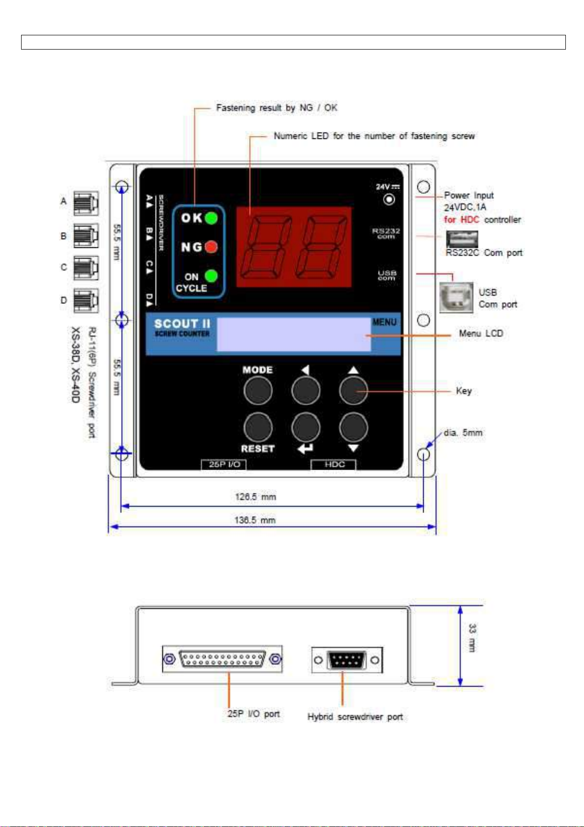
3. LAY OUT……………………………………………………………………………………………………………………...p.6
4. Caution……………………………………………………………………………………………………………………….. p.7
5. Accessories ( Option items )……………………………………………………………………………………………......p.8
6. Operation……………………………………………………………………………………………………………………...p.9
6.1 Mode………………………………………………………………………………………………………………………… p.9
6.2 Work mode…………………………………………………………………………………………………………………..p.10
6.3 Log-in mode ………………………………………………………………………………………………………………...p.10
6.4 Parameter mode…………………………………………………………………………………………………………….p.11
6.5 Measuring mod……………………………………………………………………………………………………………...p.12
6.6 Program # and parameters……………………………………………………………………………………………….. p.13
6.7 Parameters…………………………………………………………………………………………………………………. p.14
7. Interface……………………………………………………………………………………………………………………… p.17
7.1 25P I/O interface details……………………………………………………………………………………………………p.17
7.2 INPUT (Negative(-) Common wiring)……………………………………………………………………………………..p.18
7.3 INPUT (Positive(+) Common wiring) ……………………………………………………………………………………. p.19
7.4 OUTPUT (Negative(-) Common wiring) ………………………………………………………………………………… p.20
7.5 OUTPUT (Positive(+) Common wiring) ………………………………………………………………………………….p.21
7.6 Binary coding for Program selecting by 3 pins ( Pin no. 8,9 and 10 ) - P35 Enable..............................................p.22
7.7 Wiring example #1 - Tower lamp, solenoid valve, sensors, switch……………………………………………………p.23
7.8 Wiring example #2 - Inter-Lock of two screwdriver with Mid-Count signal setting…………………………………..p.24
7.9 Connecting to Hybrid HDC controller……………………………………………………………………………………..p.26
8. Timing Chart…………………………………………………………………………………………………………………. p.27
9. Timing chart details for NG / OK set up……………………………………………………………………………….......p.28
9.1 Fastening OK………………………………………………………………………………………………………………..p.28
9.2 Fastening ERROR 1 - TIME LAPSE……………………………………………………………………………………...p.28
9.3 Fastening ERROR 2 - TIME OVER……………………………………………………………………………………....p.29
9.4 Fastening ERROR 3 - NO TORQUE UP ( Most common mistake in assembly )…………………………………...p.29
10. Cycle Start / Stop in the various operating conditions……………………………………………………………........ p.30
10.1 Auto Start…………………………………………………………………………………………………………………..p.30
10.2 Start ( Continuous ON )…………………………………………………………………………………………………..p.30
10.3 Start (pulse) + Stop by time limit (Optional)…………………………………………………………………………….p.31
10.4 Start (pulse) + Stop (pulse)……………………………………………………………………………………………… p.33
11. RS-232C & USB communication port………………………………………………………………………………….... p.34
11.1 Protocol................................................................................................................................................................p.35
11.1.1 Protocol frame.................................................................................................................................................. p.35
11.1.2 Communication control letter............................................................................................................................p.35
11.1.3 Command.........................................................................................................................................................p.36
11.1.4 Check sum (BBC).............................................................................................................................................p.36
11.2 Parameter change and save................................................................................................................................p.36
11.3 Monitoring data output.........................................................................................................................................p.37
12. PC communication software, SCOUT II-Manager (for MS Windows)………………………......…………………… p.38
12.1 Software install…………………………………………………………………………………………………………….p.38
12.2 How to use…………………………………………………………………………………………………………………p.38

Instructions manual / Electric screwdrivers
5
1. Specification
No Description Specification
1 Input power
1. 30~40VDC from XS-38D (XS-40D)
2. External power of 24VDC, 1A for Hybrid controller
2 Available tools
XS-38D, XS-40D, HDC-30i, HDC-40i
3 No of Program
8 programs
4 Count number
99 for each program
5 Screwdriver port
4 ports for XS-38D (XS-40D)
1 port for HDC-30i, HDC-40i
6 Com port
RS232C, USB(B)
7 I/O
Input 15, Output 7
8 PC software
Scout Manager (on Windows)
9 Parameter setting
on front panel or PC software
10 Program share
Maximum 4 screwdrivers (with XS-38D v4.3 or XS-40D)
can share one program
- Only one(1) XS-38D with the version lower than v4.3
can be connected to Scout II
2. Main features of SCOUT II
- Maximum 5 screwdrivers can share one program of Scout ( 4 of XS-38D v4.3 or XS-40D through A,B,C,D port + 1 extra
one through 25P I/O )
- OK / NG judgment for each fastening
- Display of the remaining screw number to be fastened
- Variable signal type of the cycle start and stop
- Error display with beep sound
- Display of the fastening error information
- Built in Fastening time measurement function
- No extra power is required for XS-38D, XS-40D
- External power (24VDC) is required for HDC or other tools through 25P I/O

Instructions manual / Electric screwdrivers
6
3. LAY OUT

Instructions manual / Electric screwdrivers
7
1) The power is supplied from XS-38D or XS-40D controller to Scout through RJ-11 "A" screwdriver port.
The screwdriver port "A" works for power feeding from the connected controller XS-38D or XS-40D additionally.
If the screwdriver port "A" is empty (not used), then external power (24VDC, 1A) is required.
2) Scout II have 4 screwdriver ports for direct connecting of XS-38D and XS -40D.
Also one extra screwdriver can be connected through 25P I/O.
3) Cycle can be started by the signal from PLC, sensor or other equipment.
Also Scout gives the cycle complete signal to PLC or other equipment, too through the 25P I/O port.
4) The numeric LED shows the number of screws which should be fastened for a cycle.
5) Power Input (24VDC,1A) is required when the Hybrid screwdriver is connected.
Don't connect both XS-38D (or XS-40D) and HDC controller together to Scout II.
6) Fastening results are displayed by NG or OK for every fastening.
In order to use NG/OK judgment, the different parameter settings can be saved on the program no. from 1 to 8.
7) Parameter setting is also possible on Scout Manager (pc software).
It transmits the settings to Scout II.
The settings on programs can be saved in .csv format file.
4. Caution
1) The screw counter SCOUT II should be used with XS-38D or XS-40D controller only.
Never use the screw counter with any other tools not specified by the manufacturer.
It can be dangerous by the electrical shock.
2) Be careful of right connecting cable between the screwdriver controller and Scout II.
3) Never use non specified cable by the manufacturer.
4) Don't connect both XS-38D (or XS-40D) and HDC controller together to Scout II.
5) Do not use the screw counter near fire and magnetic environment.

Instructions manual / Electric screwdrivers
8
5. Accessories ( Option items )

Instructions manual / Electric screwdrivers
9
6. Operation
6.1 Mode
By pressing the MODE button, it circulates Work, Log-in, Parameter and
Measuring mode.
Work means operating. Before parameter mode, password is required.
Every setting is possible in Parameter mode.
Once logged in, it circulates Work, Parameter and Measuring mode, until
the power is off and on again. Fastening time is monitored on Measuring mode.
Minimum and Maximum measured time can be saved on the selected program #.
Factory setting password : " 0 "

Instructions manual / Electric screwdrivers
10
6.2 Work mode
6.3 Log-in mode

Instructions manual / Electric screwdrivers
11
6.4 Parameter mode

Instructions manual / Electric screwdrivers
12
6.5 Measuring mode

Instructions manual / Electric screwdrivers
13
6.6 Program # and parameters
The program numbers from 1 to 8 are effected together with parameters 1~8 for number of screws, P9~16 for minimum
tightening time, P17~24 for maximum tightening time, and P38~45 tear mid count number.

Instructions manual / Electric screwdrivers
14
6.7 Parameters
P # Name Specification Default
P01-P08 Program #
Save total number of screws on P1-8
1
P09-P16 Minimum tightening time
Minimum screw tightening time
Input : 0.000 - 9.999 sec ( "0" : No use )
0
P17-P24 Maximum tightening time
Maximum screw tightening time
Input : 0.000 - 9.999 sec ( "0" : No use )
0
P25 Type of cycle start and stop
Select one of 4 types of Cycle Start signal
input
0 : Auto
1 : Start (continuous ON)
2 : Start (pulse ON) + Stop (timer on P27)
3 : Start (pulse ON) + Stop (pulse ON)
0
P26 Input signal type
Select one of 2 signal type
0 : Active High ( 0 --> 1 )
1 : Active Low ( 1 --> 0 )
When Active Low is selected, the only
one(1) screwdriver ("A") can be
connected.
0
P27 Timer setting for
Cycle start/stop type
2 of P25
Input screw tightening time limit after Cycle
start signal
Input : 0.0 - 9.9 sec ( "0" : No use )
0
P28 Minimum time to judgement
Set the minimum time to judgement of
OK/NG
Input : 0 - 99 ( x 0.1s ) ( "0" : No use )
0
P29 Com port select
Select one of two com ports.
0 : USB
1 : RS-232C
0
P30 Hybrid HDC connect
Select one of two condition
0 : Not Connected (not use)
1 : Connected (used)
0

Instructions manual / Electric screwdrivers
15
P # Name Specification Default
P31 Fastening buzzer
Select one of followings
0 : Not use
1 : OK only
2 : NG only
3 : OK + NG
0
P32 Cycle buzzer
Select one of followings
0 : Not use
1 : OK only
2 : NG only
3 : OK + NG
0
P33 Reset key control
Select Reset key Enable / Disable
0 : Disable 1 : Enable
0
P34 Program key control
Select Program key Enable / Disable
0 : Disable 1 : Enable
0
P35 Program Select Input
with Binary code
Program Select Input by Binary code with
Pin no. 1 ~ 3
0 : Disable 1 : Enable
0
P36 Monitoring data
output setting
Select Enable / Disable of monitoring data
output through RS-232C port
0 : Disable 1 : Enable
0
P37 Cycle start signal
interval required
The interval time between Cycle complete
and new cycle start can be set between
1 ~ 10mS ( unit : 10 mS )
100
P38-P45 Mid count signal for P1~8
Count complete signal comes out after the
set number of Mid-Count during the cycle
0 : No use
1 – 99 : Count number
0
P46 Password
Key in the password in 4 numbers.
Initial factory setting password is ‘’0000’’
If the password is forgotten, click the
Menu on Scout manager control bar with
password ‘’77’’, then all parameters are
changed to the factory settings.
Once again, the factory setting password is
‘’0000’’.
P47 Initial parameters
All parameters are initialized to the factory
settings. Key in ‘’77’’ on P47 and press Enter
button

Instructions manual / Electric screwdrivers
16
P48 Auto system Lock
Driver is locked between Cycle complete and
next new Cycle start signal.
0 : Disable 1 : Enable
P49 Count UP Enable
Count number display on the panel
0 : Disable ( Count DOWN )
1 : Enable ( Count UP )
0
P50 Timer setting on
Auto cycle start
Time limit on auto cycle start makes NG
after set time
0 ~ 5.0sec ( 0 : not use ) unit : 0.1 sec
0
P51 Count delete key
Count delete key Enable/Disable
0 : Disable 1 : Enable
1
P51~56 Spare
Spare
P57 Version information
It is not allowed to change

Instructions manual / Electric screwdrivers
17
7. Interface
7.1 25P I/O interface details
The configuration of 25P I/O port for remote control is as below.
PIN no.
Configuration
IN / OUT
1 External Motor Run signal
2 External Torque Up signal
3 Cycle Start
4 Cycle Stop
5 Cycle Reset
6 Driver Lock
7 Spare 1
8 PS1 (Program selecting) PS1(P35 Enable)
9 PS2 (Program selecting) PS2(P35 Enable)
10 PS3 (Program selecting) PS3(P35 Enable)
11 PS4 (Program selecting) spare
12 PS5 (Program selecting) spare
13 PS6 (Program selecting) spare
14 PS7 (Program selecting) spare
15 PS8 (Program selecting) spare
16 Cycle complete OK
17 Cycle complete NG
18 Tightening OK
19 Tightening NG
20 Mid-count complete signal
21 Driver Lock
22 Spare 2
23 No use
24 Input COM
25 Output COM

Instructions manual / Electric screwdrivers
18
7.2 INPUT (Negative(-) Common wiring)

Instructions manual / Electric screwdrivers
19
7.3 INPUT (Positive(+) Common wiring)

Instructions manual / Electric screwdrivers
20
7.4 OUTPUT (Negative(-) Common wiring)
Table of contents