10
The S203 enables control of two dierent supply water circuits in-
dependently (H1 and H2).
Regulation of the temperature of supply water is controlled by
the outside temperature. Use of room temperature measurements
keeps room temperature more consistent.
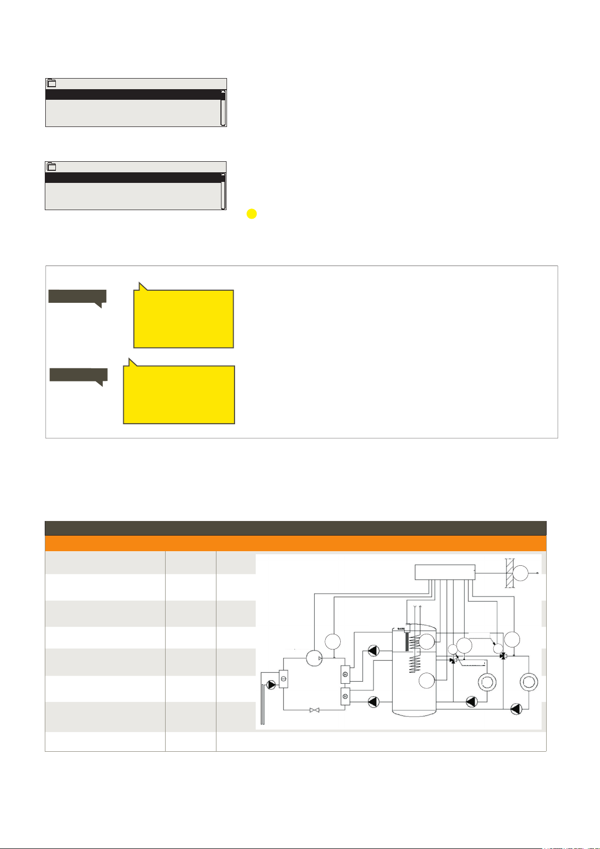
3 Regulation of supply water in heating circuits
3.1 Info
The info shows which factors are aecting currently the supply
water temperature control. The starting point is the supply water
temperature according to the outdoor temperature (according to
the heating curve).
If a room sensor is connected to the controller, you can check which
factors currently determine the room temperature setting value
at the time of inspection.
In addition the info menu contains the measurement temperature
data aecting to supply water control and information of control
of actuators.
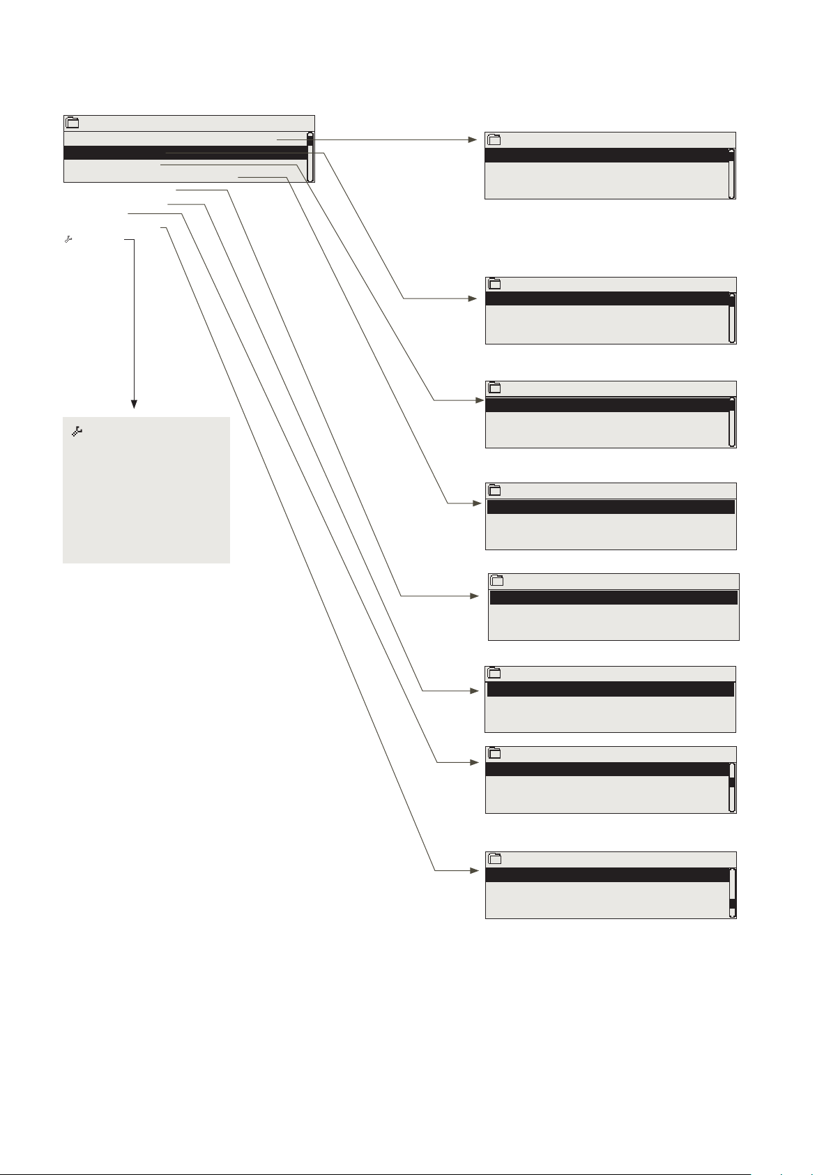
H1 (H2) Control circuit→ Info
Main menu
Inputs and outputs
H1 Control circuit
H2 Control circuit
DHW Control circuit
>
>
>
>
H1 Control circuit
Info
Heating curve
Setting values
Control mode
Time program
>
>
>
>
>
Factors eecting the supply water temp. Explanation
According to curve Supply water temperature setting according to the curve at the current outdoor
temperature.
Eect of parallel shift Eect of parallel shift on the supply water temperature.
Eect of time program Eect of weekly or exception schedule mode on the temperature of supply water.
Near the end of the temperature reduction time, the pre-increase operation can in-
crease the temperature of supply water.
Force control eect Supply water has been forced permanently to the desired temperature reduction
level (see Control mode selection).
Away -control eect ”Away” control for reduction of supply water temperature. The trigger can come
from the Home/Away switch, the controller or be sent as a text message (see 41).
Outdoor temp. delay eect The eect of the outdoor temperature delay on the supply water temperature.
Floor heat. anticipate Eect of anticipation of floor heating on the temperature of supply water.
Eect of autumn drying Eect of automatic autumn drying on the supply water temperature.
Return water compensation Increase in supply water temperature due to return water compensation.
Eect of room compensation Eect of room compensation on the supply water.
Room comp. time adjustment Additional correction for more precise room compensation based on realised regu-
lation (eect of I-regulation).
Bus compensation eect The amount of required compensation is determined by an external device to the
S203, for example from bus compensation to weather compensation.
Min limit eect Supply water temperature increase due to the minimum limit.
Max limit eect Supply water temperature drop due to the maximum limit.
Calculated supply water setting Current supply water temperature determined by the controller.
Controller is stopped for summer When the regulator is in summer function mode, the supply water information says
”Controller is stopped for summer.”
Controller is in manual control Control circuit mode is set to ” Manual control”.