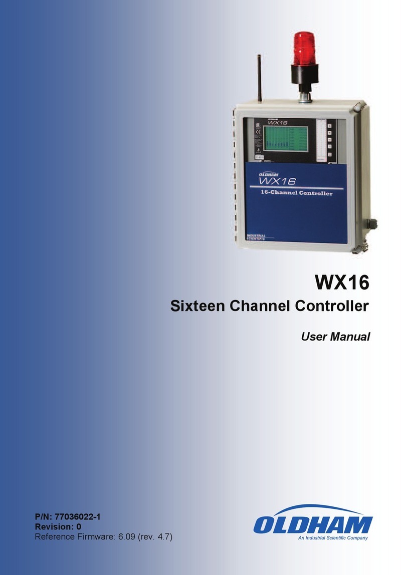
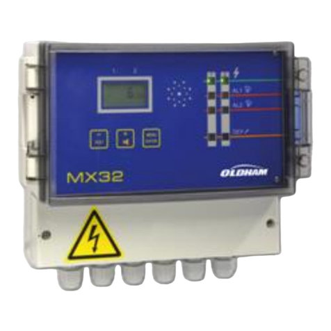
Oldham MX 32 User manual

User Manual
MX 32v2
Analog and Digital
Controller
Part Number: NP32V2EN
Revision: C.0
The Fixed Gas Detection Experts

II
MX 32v2
User Manual
Copyright January 2018 by Oldham S.A.S.
All rights reserved. The reproduction of all or any section of this document in
any form whatsoever without the written permission of Oldham S.A.S. is
forbidden.
The information contained in this manual is accurate to our knowledge.
As a result of continuous research and development, the specifications of this
product may be modified at any time without prior notice.
Oldham S.A.S.
Rue Orfila
Z.I. Est –CS 20417
62027 ARRAS Cedex
Tel.: +33 (0)3 21 60 80 80
Fax: +33 (0)3 21 60 80 00
E-mail: info@oldhamgas.com
Website: https://gasdetection.3M.com

Table of Contents
iii
Tableofcontents
Chapter 1 │General Information ....................................................... 1
User Manual ...................................................................................................1
Symbols used.................................................................................................1
Safety Instructions..........................................................................................2
Important Information .....................................................................................2
Liability Limits.................................................................................................2
Warranty.........................................................................................................2
Chapter 2 │General Introduction...................................................... 3
Purpose of the MX 32 controller .....................................................................3
The different Versions ....................................................................................5
Firmplate ........................................................................................................6
The COM 32 Software....................................................................................6
Chapter 3 Mechanical Installation .................................................... 7
MX 32 Controller.............................................................................................7
Gas detectors.................................................................................................8
Digital Modules...............................................................................................8
Chapter 4 │The MX 32 Controller ..................................................... 9
Overview of the Unit .......................................................................................9
Front Plate....................................................................................................12
Alarm Thresholds and Relays.......................................................................15
Firmplate ......................................................................................................16
Chapter 5 │Digital Modules .............................................................17
Addressable Digital Modules ........................................................................17
RS485 Transmission ....................................................................................18
Communication Setup ..................................................................................18
Relay modules..............................................................................................20
16-Logic Input Module ..................................................................................22
8-Analog Input Module..................................................................................23
4-Analog Output Module...............................................................................25
Chapter 6 │Wiring and Electrical Connections...............................27
Controller Connection...................................................................................27

iv
MX 32v2
User Manual
4- or 8-Relay Modules ..................................................................................30
16-Logic Input Module..................................................................................31
8-Analog Input Module..................................................................................31
4 Analog Output Module...............................................................................32
Chapter 7 │Menus............................................................................33
General Menu Tree ......................................................................................33
Navigation Key Functions.............................................................................33
Display in normal mode................................................................................34
Main Menu....................................................................................................35
1. System .....................................................................................................35
2. Program....................................................................................................36
3. Calibration ................................................................................................36
4. Maintenance.............................................................................................40
5. Information ...............................................................................................41
Chapter 8 │Main Part Numbers .......................................................45
Chapter 9 │Cleaning and maintenance ...........................................47
Cleaning .......................................................................................................47
Fuse replacement.........................................................................................47
Replacement of the lithium battery ...............................................................47
Chapter 10│Certificate of Compliance .............................................49
Chapter 11│Technical Specifications ..............................................51
MX 32 Controller...........................................................................................51
Relay Module................................................................................................53
16-Logic Input Module..................................................................................53
8-Analog Input Module..................................................................................54
4-Analog Output Module...............................................................................54
Chapter 12| RS485 Digital Output.....................................................55
Card description ...........................................................................................55
Transfer Table..............................................................................................56
Address Table ..............................................................................................57
Chapter 13│ Specific conditions of use and Functional Safety ......63
Reliability data..............................................................................................63
Specific Conditions of Use............................................................................63
Specific instructions for the prevention of explosions according to ATEX
2014/34/EU European Directive ...................................................................64
Connecting detectors other than Oldham detectors to the MX 32 controller.65

1 –General Information
1
Chapter 1 │General Information
User Manual
The instructions given in this manual must be read thoroughly before
installation and start-up, particularly those concerning the points related to the
safety of the end-user. This user manual must be made available to every
person involved in the activation, use, maintenance, and repair of the unit.
The information, technical data, and diagrams contained in this manual are
based on the information that is available at a given time. In case of doubt,
contact Oldham for additional information.
The aim of this manual is to supply simple and accurate information to the
user. Oldham cannot be held liable for any misinterpretations in the reading of
this manual. In spite of our efforts to produce an error-free manual, it may
nonetheless contain some unintentional technical inaccuracies.
In the client’s interest, Oldham reserves the right to modify the technical
characteristics of its equipment to increase their performance without prior
notice.
The present instructions and their content are the inalienable property of
Oldham.
Symbols used
Icon
Significance
This symbol indicates useful additional information.
This symbol indicates:
Earth ground connection.
This symbol denotes:
Protective earth terminal. A cable of the adequate diameter must
be connected to ground and to the terminal having this symbol.
This symbol denotes:
Attention! In the present mode of use, failure to adhere to
the instructions preceded by this symbol can result in a risk
of electric shock and/or death.
This symbol indicates:
You must refer to the instructions.

2
MX 32v2
User Manual
European Union (and EEA) only. This symbol indicates that this
product must not be discarded with household waste, as per the
EEA directive (2002/96/EC) and your own national regulations.
This product must be disposed of at a collection point that is
reserved for this purpose, for example, an official site for the
collection of electrical and electronic equipment (EEE) in view of
their recycling, or a point of exchange for authorized products
that is accessible when you acquire a new product of the same
type.
Safety Instructions
Labels intended to remind you of the principal precautions of use have been
placed on the unit in the form of pictograms. These labels are considered an
integral part of the unit. If a label falls off or becomes illegible, please ensure it
is replaced. The significance of the labels is detailed below.
The installation and electrical connections must be carried out by
qualified personnel according to the instructions of the
manufacturer and the standards of the competent authorities.
Failure to adhere to the instructions can have serious
consequences on the safety of persons. Please be extremely
rigorous as regards electricity and assembly (coupling, network
connections).
Cables with an operating temperature of 70°C minimum (158 °F)
must be used because the temperature inside the controller can
reach 70°C (158 °F).
Important Information
The modification of the material and the use of parts of an unspecified origin
shall entail the cancellation of any form of warranty.
The use of the unit has been projected for the applications specified in the
technical characteristics. Exceeding the indicated values cannot in any case
be authorized.
Liability Limits
Neither Oldham nor any other associated company under any circumstances
can be held liable for any damage, including, without limitations, damages for
loss or interruption of manufacture, loss of information, defect of the MX 32
controller, injuries, loss of time, financial or material loss, or any direct or
indirect consequence of loss occurring in the context of the use or
impossibility of use of the product, even in the event that Oldham has been
informed of such damage.
Warranty
Under normal conditions of use and on return to the factory, parts and
workmanship carry a two year warranty, excluding consumables such as
backup power supplies, audio and visible alarms, etc.

2 –General introduction
3
Chapter 2 │General Introduction
Purpose of the MX 32 controller
This controller is intended for the continuous measurement and control of the
gases present in the atmosphere.
MX 32
8 relay output modules and 4
4-20mA output modules
Figure 1: MX 32 and examples of the modules
The system primarily comprises:
■a MX 32 (1 or 2 lines),
■different modules (analog or digital detectors, logic inputs, analog inputs,
relay outputs, and analog outputs).
The MX 32 instantly handles the measurements of detectors and input
modules. As soon as the measurements reach the configured thresholds, the
internal buzzer and the LED indicators go off. At the same time, the
corresponding relays are activated to drive the additional actions programmed
by the user.
The MX 32 controller is programmed by using the COM 32 configuration
software.
Figure 2 presents a configuration example.

4
MX 32v2
User Manual
Figure 2: Example of an MX 32 configuration using different analog and digital detectors
as well as digital modules
MX 32
Configuring PC with the
COM 32 application
Digital detectors
2 logic
inputs
Analog recorders
Four 4-20mA Analog
Output Module
8 Relay Output Module
Logic Input Module
4 Relay Output
Module
16 logic
inputs
Analog inputs
External
power supply
USB
link
8 Analog Input Module

2 –General introduction
5
The different Versions
The MX 32 controller is available in 3 versions:
■1 line,
■2 lines,
■Bridge Version (2 channels) for direct monitoring of Wheatstone bridge
flammable gas detectors.
Figure 3: MX 32
The following table details the different possible configurations depending on
the controller’s version. On each line, it is possible to connect 4-20mA analog
detectors or digital addressable modules.
Maximum Capacity
Version
Detectors
Analog Input
Modules
Relay Output
Modules
Logic Input
Modules
Analog
Output
Modules
1 line
4
1
2
1
1
2 lines
8
2
4
2
2
Wheatstone Bridge
2(1)
0
0
0
0
(1) OLC 10, OLC 10Twin or OLC 100 flammable gas detectors
Maximum Capacity
Version
External Relays
Logic Inputs
Analog Outputs
1 line
8
16
4
2 lines
16
16
8
Wheatstone Bridge
0
0
0
Table 1: Summary of the maximum capacity as per the controller type

6
MX 32v2
User Manual
Firmplate
It contains relevant information with respect to the controller version (CSA or
ATEX variants).
Tag.
Description
1.
Product Name
2.
Part Number
3.
CSA mark
4.
CE marking with identification of the Notified Body that assessed the OLDHAM
manufacturing quality system (0080 - INERIS)
5.
ATEX marking (Performance requirements of gas detection systems for flammable
gases)
6.
Serial Number. The first two digits (in this case 17) correspond to the year of
manufacture (in this case 2017).
7.
Variant (1 or 2 lines to work with 4-20mA analog detector or Oldham digital detector,
or 2 channels to work with Wheatstone bridge gas detectors). In this example,
version ‘Wheatstone Bridge’.
8.
Power supply type (24Vdc or 100-240Vac). In this example, 24Vdc type.
9.
Name and mail address of the Manufacturer
10.
Warnings
The COM 32 Software
This is intended for setting the MX 32 parameters from a Windows®operated
PC. The operation and use of this application is covered in a special training
course.
10
9
8
7
171204Y-693
4
5
6
1
2
3

3 - Mechanical Installation
7
Chapter 3 Mechanical Installation
MX 32 Controller
Location
The MX 32 is intended for indoor use only and shall be installed in premises
without explosive atmospheres, away from direct exposure to sunlight, and
protected from humidity, dust, and temperature variations. It shall preferably
be located in a monitored environment (for instance: guardhouse, control
room, or instrument room, etc.).
Attachment of the wall enclosure
Access to the controller must be ensured in order to facilitate adjustments,
monitoring, and cabling. A space of 400 mm is necessary in front of the MX 32
for opening the door. Use 3 fixing screws 4x25 mm for fixing the case support.
Figure 4: Dimensions
Figure 5: Fixing the MX 32

8
MX 32v2
User Manual
Gas detectors
Refer to the manual supplied with each detector.
Location
Each detector shall be positioned at ground level, on the ceiling, at human
height or near air extraction ducts, depending on the density of the gas to be
detected or the application. Heavy gases are detected close to the ground,
while lighter gases are present along the ceiling. If necessary, contact Oldham
for any questions regarding proper detector positioning.
Fixing
The detectors shall preferably be positioned in an accessible place so that
inspections and maintenance can be carried out as well as to ensure the
absolute safety of the operators. The detectors must not be obstructed by
anything that will prevent them from measuring the ambient environment to be
checked.
Digital Modules
For cabling and electrical information see paragraph Wiring and
Electrical Connections on page 27.
Location
The relay modules, logic outputs, analog outputs, and analog inputs are
positioned depending on the installation layout, mandatorily in places free
from explosive atmospheres, protected from humidity, dust, and temperature
variations; for example in technical cabinets.
Fixing
These modules shall be mounted on
a DIN rail in a cabinet or in an
electrical cabinet.
For relay modules connected to low
voltage electrical parts, the
installation is carried out according
to the standards in force.
Figure 6: Fixing of a module (relay, logic
outputs, or analog outputs or inputs) on a
DIN rail

4 –The MX 32 Controller
9
Chapter 4 │The MX 32 Controller
Overview of the Unit
External view
Rep.
Function
Rep.
Function
A.
Monochromatic, back-lit graphic
LCD display
F.
Toggle Latch (one is lockable)
B.
Zone 1 status indicator
G.
Power On/Off indicator
C.
Zone 2 status indicator
H.
Failure/maintenance indicator
D.
Integrated siren (option)
J.
Contextual soft keys
E.
Integrated flash (optional)
K.
Alarm Acknowledgement button
Figure 7: External view of the wall-mounted and rack-mounted versions

10
MX 32v2
User Manual
Internal view
Figure 8: Internal view (2 line version on top and Bridge version at the bottom)
Rep.
Function
A.
LCD graphic display card
B.
USB programmation port
C.
On-board additional flashlight (option)
D.
Programming (or mode) selector
0. MX 32 in normal operation.
1. Read/Write configuration program
2. MX 32 firmware update via a PC
Once the unit configuration or update is complete, always set back the selector
in the "0" position. The MX 32 will resume automatically.
E.
Microcontroller reset button. Press this button to reset the controller.

4 –The MX 32 Controller
11
Rep.
Function
F.
On-board additional siren, settable from 85 to 100dB (option)
G.
CR2032 lithium battery. Allows data and real time clock saving in case of power failure.
Runtime is approx. 450 days while power off. Keep the MX 32 powered during battery
replacement.
H.
100-240Vac (50-60Hz) input terminal
I
100-240Vac / 24Vdc power supply (option)
J
22-28Vdc input terminal. Allows the use of an external power supply (read External 24Vdc
Power Supply, page 28)
K.
Display contrast setting
L.
Remote acknowledgement input terminal (NO dry relay contact)
M
Cable glands; 5 x M16 + 2 x M20
N
Line #1 terminal (1 to 2 lines depending on the version)
O.
Digital communication status LED indicators (Line #1 on left, Line #2 on right). The
information displayed by each pair of LEDs is interpreted as follows:
LED Status
Significance
Fast blinking
Fast blinking
Line is in normal operation mode
- Tx: sends queries to the attached modules
- Rx: receives data from attached modules
Irregular
blinking
Irregular
blinking
Bad communication quality with at least one module.
Blinks 1 time
per sec
Off
Communication failure. Absence or failure of one
module
On communication failure, the internal buzzer, the
failure indicator and the Fault relay are activated.
Off
Off
No active module is present on the line
P.
Grounding terminals to connect cable shield for digital and analog connections
Q
From top to bottom, relay alarm terminals (R1 to R4 respectively). DPCO relays, contacts
rating 250Vac-30Vdc / 5A
R.
Fault and Alarms relays (2 relays are located under the power supply; tag I). From top to
bottom:
- Fault (Fault relay, non-configurable)
- R1, R2, R3, R4 (alarm relays, configurable)
Configuration of Alarm Relays
Alarm relays are to be programmed with COM 32 software. The PCB printing displays
while unpowered. R1 to R4 relays can be configured as normally energized (the coil is
powered when not in alarm) or normally de-energized (the coil is powered when in alarm).
There are different way to program the relays:
- Normal mode: relay operates as the alarm sequence. The sure can set a delay and
chose the relay to be latched or unlatched (see Alarm Acknowledgement, page 16).
- Buzzer mode: This mode is usually used for audible alarms management. The ‘buzzer’
relay acts as a ‘normal’ relay but can be acknowledged even if the alarm is still present
(in order to turn the siren off).

12
MX 32v2
User Manual
Rep.
Function
The time delays are:
. Reset Inhibit: Minimum time of activation, adjustable from 0 to 900 seconds.
. Automatic reset: Time adjustable between 15 and 900 seconds, beyond which the
buzzer relay is automatically deactivated.
. Reactivation time: Time adjustable between 15 and 900 seconds, beyond which the
buzzer relay is automatically reactivated if the alarm is still present.
Alarm Relay Management
- by the logic operators OR, AND, NOR, NAND. Up to 4 levels of parentheses. The result
of the equation controls the relay.
- Voting operation (x out of y): There must be at least “x” events out of “y” to activate the
relay. Depending on user’s programmation, a FAUT event can be treated as an alarm
event.
S.
Relays status DEL indicator. Illuminated when the corresponding relay coil is ON.
T.
4 Amp fuse, protects the 24V power supply input
U.
Modbus RS485 communication board (option, see page 55)
V.
Zero setting potentiometer (on the left line #1, on the right line #2)
W.
Span setting potentiometer (on the left line #1, on the right line #2)
X.
Catalytic bead current adjustment (top line #1, bottom line #2). Settings are reserved to
authorized personel
Y.
Faut relay terminal. DPCO relay, 250Vac-30Vdc / 5A
Front Plate
Figure 9: MX 32’s front plate
LCD (A)
The display shows the measurements or the settings menus. When an alarm
occurs, the display turns in grayscale mode to indicate the channel that is
currently displayed is on alarm.

4 –The MX 32 Controller
13
Figure 10: Display of the measurement (on the left) or parameter settings display (on the
right)
Refer to paragraph Menus on page xx for more details about the information
that are available on the screen.
Contextual Keys (B)
The function of each of the 5 keys indicated in the lower part of the display
changes depending on the page displayed.
Zone Status Indicators (C)
The two bars of 7 indicators represent two zones. The detectors that are
connected to the controller can be assigned to one of the two zones by using
COM 32 configuration software.
Each bar displays the status of the group of detectors of the pertinent zone as
follows:
Icon
Function
Orange indicator of high-range excess (OVS: overscale, high-range excess). This
value is adjustable up to 110% of the range.
- Off: The measurement is lower than the OVS value programmed.
- Lit: The measurement is higher than the OVS value programmed. The alarm
relays are activated in accordance with the program. In parallel, the display
indicates « > ».
OVS acknowledgement must be done manually and is only possible if the current
value drops below the programmed value.
Management of “Non-Ambiguity Reading”
The Non-Ambiguity Reading function only applies to the monitoring of flammable
gases in a range of 0-100%LEL, and is subject to the decision of the operator.
Upon the detection of a concentration of gas higher than 100% LEL, the LCD
indicates > 100% LEL –Frozen value –High Concentration - System in Fault
Condition. The OVS and FAILURE indicators are activated. Such an alarm can
only be deactivated by turning off the detector via the maintenance menu once the
current gas level is below the programmed OVS limit.
ALARM3
ALARM2
ALARM1
Alarm status red indicators:
- Off: No alarm
- Solid: at least one gas detector of the corresponding zone is in alarm condition.
Acknowledgment is programmed in automatic mode or the alarm reset button
located on the front panel has already been pushed.
- Blinking: at least one gas detector of the corresponding zone is in alarm
condition. Acknowledgment is programmed in manual mode and has not been
required yet.

14
MX 32v2
User Manual
Icon
Function
Orange indicator of low- range excess (UDS: Under scale, low-range excess). This
value is adjustable from 0-10% of the range.
- Off: The measurement is higher than the UDS value programmed.
- Lit: The measurement is lower or equal than the UDS value programmed. The
alarms of the relays are activated in accordance with the programming. In
parallel, the display indicates « < ».
Reset of the UDS is automatic once the failure is fixed.
FAULT
Orange failure indicator
- Off: No Fault
- Solidt: Communication problem with one of the modules or invalid detector
measurement, that is to say either below -10% of the range or above 110% of
the range.
- Blinking: Controller in maintenance mode (test, calibration).
Reset of the FAULT is automatic once the failure is fixed.
POWER
Green start/stop indicator for the detectors/modules of the zone.
- Off: All detectors of the corresponding zone have been turned off
- Solid: At least one detector of the corresponding zone is communicating
- Blinking: Detailed information of one detector of the corresponding zone are
currently displayed on the LCD screen.
Flash and siren (D and E)
Siren (
Figure 9: MX 32’s front plateE)
Available as an option, adjustable from 85 to 100dB, it complements the
internal buzzer and is configured via COM 32 configuration software.
Flash (
Figure 9: MX 32’s front plateD)
Available as an option, blue or red, is configurable via COM 32.
Status indicators (F and G)
These two indicators reflect the status of the MX 32.
Icon
Function
Green indicator denoting the power supply status
- Solid: Voltage input is OK
- Off: Voltage input is below 22Vdc
Failure/maintenance orange indicator
- Off: No failure detected
- Solid: Presence of some failure (controller, detector, communication, memory). The
alarm clears automatically once the failure is fixed.
- Blinking: MX 32 in maintenance mode (test, calibration).

4 –The MX 32 Controller
15
Alarm Reset Key (H)
Press this key to silence the on-board buzzer and reset the alarms that can be
acknowledged. This reset button can be remote, see paragraph Remote
Acknowledgement connector on page 30.
Alarm Thresholds and Relays
Alarm thresholds, relay programming, time delays setting, alarm
acknowledgement modes or the management of the additional flash and
sounder (
Figure 9: MX 32’s front platetags D and E) are configured though COM 32
application.
Note: It is possible to modify a programmed alarm level via the MX 32’s user
interface (Program menu).
Internal Relays and Buzzer
■4 fully configurable Alarm relays are available.
■1 Fault relay is available. This relay is not configurable and is activated on
the appearance of any failure. The Fault relay is powered in normal
operation mode so it does switch over in the event of a power supply
failure.
■The internal buzzer is activated on the appearance of any event (failure or
alarm). The sound differs depending on the event: continuous in fault
mode, discontinuous in alarm mode and frequency increases according to
the alarm level that is reached. The internal buzzer can be deactivated
permanently through the user interface or COM 32 application.
Alarms Settings
It is possible to program for each detector:
■3 alarm levels
■each alarm can be increasing or decreasing
■each alarm can be configured as an instantaneous alarm and/or an
averaged alarm over 15 to 480 minutes
■each alarm has an adjustable hysteresis from 0 to +3% of the measuring
range by increments of 1%
■one over range alarm (OVS: over scale)
■one under range alarm (UDS: underscale)
■one “no ambiguity” alarm (for flammable gas detectors and concentrations
above 100% LEL)
Alarms may be programmed for automatic or manual acknowledgement
(except OVS, UDS, “no ambiguity”).

16
MX 32v2
User Manual
Alarms Automatic Acknowledgement
In this mode, resetting an alarm does not require any intervention. Alarm
management (relays, visual indicators, buzzer) is as follows:
Event
Display
Alarm Relay
(normal mode)
Alarm Relay
(buzzermode)
Alarm
LED
Internal
buzzer
Alarm
Appearance
AL (1,2,3)
grayscale
mode
Activated
Activated
Solid
ON
Alarm Reset
ispressed
AL (1,2,3)
grayscale
mode
Activated
Deactivated
Solid
OFF
Alarm
Disappearance
Normal
mode
Deactivated(a)
Deactivated(a)
OFF
(b)
(a): Automatic deactivation upon alarm disappearance even if Alarm Reset button was not
pressed
(b): Manual acknowledgement (press Alarm Reset) is mandatory to silence the internal buzzer
Table 2: Alarms in Automatic Acknowledgement mode
Alarms Manual Acknowledgement
In this mode, Alarms must be reset by the operator. Alarm management
(relays, visual indicators, buzzer) is as follows:
Event
Display
Alarm Relay
(normal mode)
Alarm Relay
(buzzermode)
Alarm LED
Internal
buzzer
Alarm
Appearance
AL(1,2,3)
grayscale
mode
Activated
Activated
Blinking
ON
Alarm Reset
ispressed
AL(1,2,3)
grayscale
mode
Activated if
event is still
present
Deactivated
Solid if
event is still
present
OFF
AL(1,2,3)
grayscale
mode
Deactivated if
the event has
disappeared
Deactivated
OFF if the
event has
disappeared
OFF
Alarm
Disappearance
Normal
mode(a)
Deactivated(a)
Deactivated(a)
OFF(a)
OFF(a)
(a): Once Alarm Reset button has been pressed
Table 3: Alarms in Manual Acknowledgement mode
Firmplate
Firmplates are attached on the right side, on the top and behing the front
cover of the MX 32. Following information can be found:
■Model (1 or 2 lines and power supply type)
■Electrical Specifications (power consumption, fuse)
■P/N and S/N
■Warnings and Approval Markings
■Logo and manufacturer’s details
Other manuals for MX 32
1
Table of contents
Other Oldham Controllers manuals