OLEI LR-1BS2 User manual

Sensing Reality!
Please read this user manual for best product performance before using the product.
Be sure to keep this manual properly for future reference.
LiDAR Sensors
LR-1BS2
User Manual
OMEN-1BS2-202202

User Manual LR-1BS2
OMEN-1BS2-202202
2
Contents
1. About this document........................................................................................................................ 3
2. Safety information............................................................................................................................ 3
3. Product introduction......................................................................................................................... 3
4. Installation and operation................................................................................................................. 3
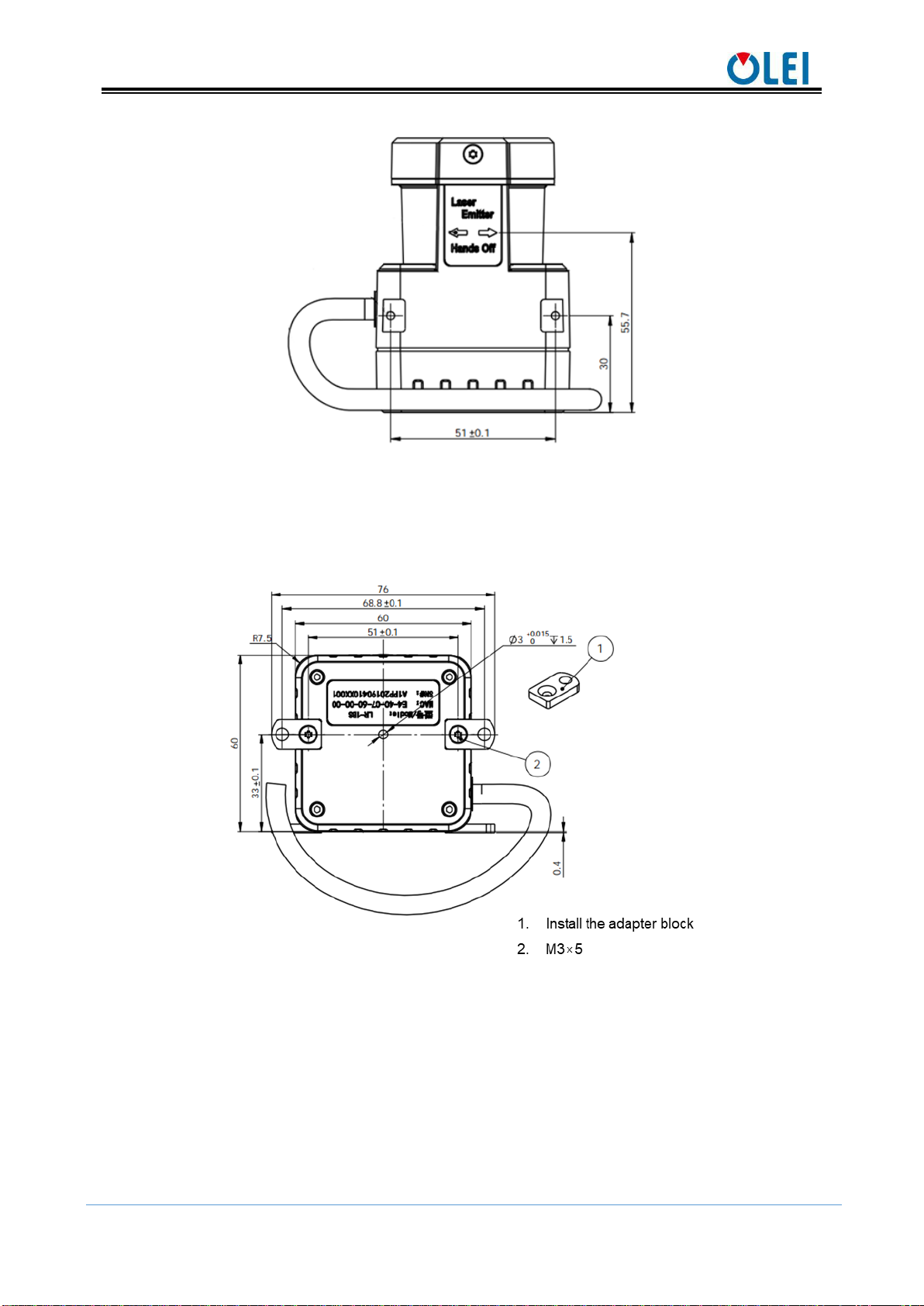
4.1. Mechanical interface................................................................................................................ 3
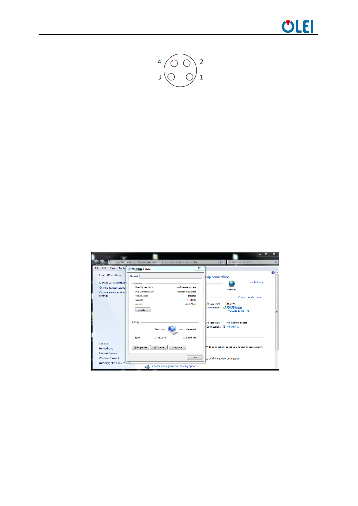
4.2. Pin and wire color assignments................................................................................................ 4
4.3. Communication interface......................................................................................................... 6
5. Measurement principle..................................................................................................................... 8
6. Parameter configuration................................................................................................................... 8
6.1. Parameter configuration of web page....................................................................................... 8
6.2. Parameter configuration of filter level..................................................................................... 9
6.3. Description of indicator light ................................................................................................. 10
6.4. Description of field ................................................................................................................ 10
7. Troubleshooting ............................................................................................................................. 12
Appendix A Mechanical Dimensions............................................................................................... 13
Appendix B Example for electrical connection................................................................................ 14
Appendix C Data Packet .................................................................................................................. 15
Appendix D Firmware Upgrade....................................................................................................... 16
Appendix E Oforge........................................................................................................................... 17
E.1 Software Installation................................................................................................................ 17
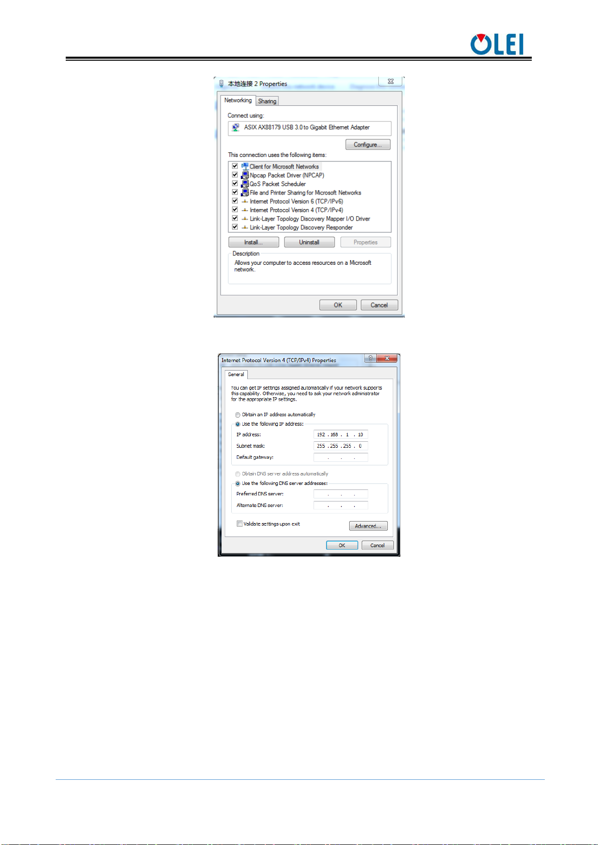
E.2 Network Configuration............................................................................................................ 17
E.3 Software interface.................................................................................................................... 19
E.4 Menu composition and menu options...................................................................................... 19
E.5 Software usage......................................................................................................................... 20
E.6 Introduction of LiDAR Info interface...................................................................................... 22
Appendix F Notes on mounting ....................................................................................................... 23
Appendix G Cleaning of sensor ....................................................................................................... 25
G.1 Notice ...................................................................................................................................... 25
G.2 Materials required.................................................................................................................... 25
G.3 Cleaning method...................................................................................................................... 25

User Manual LR-1BS2
OMEN-1BS2-202202
3
1. About this document
This document summarizes supplementary information on mounting and electrical
installation as well as measured value output format of the LR-1BS2. It is aimed at
sufficiently qualified personnel for the purposes of installation, commissioning and further
data processing. Notes on commissioning, configuration and maintenance can be found in the
LR-1BS2 operating instructions
2. Safety information
Read the notes on mounting and electrical installation before carrying out these tasks.;
Read additionally the LR-1BS2 operating instructions to familiarize yourself with the
device and its functions;
The LR-1BS2 complies with laser class 1.
Only use the device in permissible ambient conditions (e.g. temperature, ground
potential). Any applicable legal regulations or regulations of other authorities will have to
be observed during operation.
Opening the screws of the LiDAR housing will invalidate any warranty claims against
OLEI.
Repairs may only be performed on the LiDAR by trained and authorized OLEI service
personnel
3. Product introduction
The LR-1BS2 is an opto-electronic laser scanner that electro-sensitively scans the
perimeter of its surroundings at a single plane with the aid of laser beams. The LR-1BS2
measures its surroundings using two-dimensional polar coordinates based on its measurement
origin. It can output both point cloud data output and safety signal (I/O port).
Thus LR-1BS2 has been widely applied to industries such as robot obstacle avoidance,
safety monitoring, industrial automation, and intelligent logistics.
4. Installation and operation
4.1. Mechanical interface
The LiDAR can be installed in two ways: back-mounted and bottom-mounted.
Back-mounted
There are two M3 screw holes (hole depth is 3mm) at the back of the LiDAR.

User Manual LR-1BS2
OMEN-1BS2-202202
4
Figure 1: Back mounting interface of LR-1BS2
Bottom-mounted
There are two M3 screw holes (hole depth is 3mm) at the bottom of the LiDAR.
Figure 2: Bottom mounting interface of LR-1BS2
4.2. Pin and wire color assignments
LR-1BS2 is equipped with a 2-meter "Power/IO" cable and an "Ethernet" connection.

User Manual LR-1BS2
OMEN-1BS2-202202
5
Figure 3 Diagram of electrical interface
4.2.1 "Power/IO" cable
NO.
Definition
Cable color
1
LiDAR power_VCC
(12~30VDC)
red
2
LiDAR power_GND
black
3
Input 0: Input port 0
orange
4
Input 1: Input port 1
white
5
Input 2: Input port 2
light blue
6
Input 3: Input port 3
dark blue
7
Output 0: output port 0 (LiDAR error output)
brown
8
Output 1: Output port 1 (Corresponding to the
software Level 1 area)
yellow
9
Output 2: Output port 2 (Corresponding to the
software Level 2 area)
green
10
Output 3: Output port 3 (Corresponding to the
software Level 3 area)
purple
11
I/O power_VCC
(12~30VDC)
pink
12
I/O power_GND
gray
Table 1 Definition of "Power/IO" cable
Note: When "Output0" outputs a high-level signal, it means that the LiDAR is abnormal,
please suspend using.
4.2.2 Ethernet connection
Table 2 Definition of Ethernet connection
NO.
definition
1
TxData+: Send+
2
TxData-: Send-
3
RxData+: Receive+
4
RxData-: Receive-

User Manual LR-1BS2
OMEN-1BS2-202202
6
Figure 4 Diagram of Ethernet connection
4.3. Communication interface
The LR-1BS2 is connected to the computer by a RJ-45 Ethernet interface. The computer
IP address should be set up before communication. The LiDAR and computer IP must be set
up in the same subnet without any conflict. The host port is 2368 by default.
The factory default settings are as follows
Computer IP:192.168.1.10
Computer subnet mask:255.255.255.0
The default factory settings of LiDAR are as follows
LiDAR IP:192.168.1.100
LiDAR subnet mask:255.255.255.0
The operation steps are as follows
Figure 5: Step 1 of computer IP setting

User Manual LR-1BS2
OMEN-1BS2-202202
7
Figure 6: Step 2 of computer IP setting
Figure 7: Step 3 of computer IP setting

User Manual LR-1BS2
OMEN-1BS2-202202
8
5. Measurement principle
Figure 8 Diagram of LR-1BS2 LiDAR work principle
As is shown in the figure above, LR-1BS2 measures distance by using the time-of-flight
principle. The LiDAR emits pulsed laser beams using a laser diode. If one of these laser
pulses hits an object or a person, this is reflected at its surface. The reflection is detected in
the LiDAR's receiver by a photodiode. The LiDAR calculates the distance to the object from
the transit time required by the light from emission of the beam to receipt of the reflection.
The calculation method is as follows:
𝐷 = 𝐶𝑇
2
D —Detection range
T —Flight time
C —Speed of light
6. Parameter configuration
6.1. Parameter configuration of web page
Web page parameter configuration method of LR-1BS2 is as follows:
Open the browser (please use Chrome,Firefox, Edge or other standard browsers),
and enter the LiDAR IP address;
"Model" and "Version" at the top of the UI indicate the product model and
firmware version;
"Temperature", "Voltage" and "SafeArea" on the right side of the UI are the
LiDAR parameters displayed in real time, indicating the temperature, voltage and
current active Bank. When the font color of parameter turns red, please check
whether the LiDAR is malfunctioning;
Automatically read the current settings of LiDAR by refreshing the page;
Select the desired speed through "Motor RPM": 600/900/1200/1500
(The corresponding scanning frequency is 10/15/20/25HZ ), and click "Set
Configs" to confirm;
Laser transmitter
Detector

User Manual LR-1BS2
OMEN-1BS2-202202
9
Set the LED indicator ON and OFF through "Led Marquee", and click "Set
Configs" to confirm;
Set the ON and OFF of the LiDAR safety function through "Safe Area", and click
"Set Configs" to confirm;
Select input mode of "safe bank" trough "Safe bank input";
Set the mode of the LED indicator through "Led Mode";
Select current Bank through "Safe bank config" when "Safe bank input" is
“Software”;
Set receiving computer IP and port through "Host IP & Port".Up to 3 groups can
be set. Click to add a group, click to delete a group.
Enable/disable the DHCP function: the LiDAR dynamically obtains an IP address
from the DHCP server (ON), and the LiDAR needs to set up a static IP address
(OFF);
Modification of LiDAR IP: Enter the new IP into the LiDAR IP column (must be in
the same network segment as the local IP), click the "Set Network" to confirm, and
the modification is complete after the LiDAR is powered on again
Figure 9 Parameter configuration of web page
6.2. Parameter configuration of filter level
The web page parameter configuration method is as follows:
Open the browser (please use Chrome, Firefox, Edge or other standard browsers),
enter http://LIDAR IP/advanced.html; (the factory default address is:192.168.1.100)
Over range as: Select the point that exceeds the range to output as the maximum
range or display as 0;
Weak points filter: set the strength of weak point filter ;

User Manual LR-1BS2
OMEN-1BS2-202202
10
Tail points filter: set the strength of tail points filter;
Figure 10 Parameter configuration of filter level
6.3. Description of indicator light
When the Led Mode is Mode1, the light style is shown as the following table
Table 3 Description of indicator light
6.4. Description of field
Security field group
Indicator light
Description
White light
(flashing)
Initialization
Red light
(flashing)
Abnormality occurs, please check the internal voltage or temperature
through the web page
Green light
(rolling)
Operates normally
Red light
(rolling)
Level 1 area is triggered, still only the red light is displayed if both Level 2
and Level 3 areas are triggered,
Yellow light
(rolling)
Level 2 area is triggered, still only the yellow light is displayed if the Level
3 area is triggered
Blue light
(rolling)
Level 3 area is triggered.

User Manual LR-1BS2
OMEN-1BS2-202202
11
The corresponding relationship between the security field group (BANK) and the switch
value of the input (Input) port of LR-1BS2 is shown in the following table.
□indicating low level, ☑indicating high level.
Table 4 The relationship between field group and input port switch
Note:Only one group of BANK is valid at any time;
Bank 0 is activated if I/O port is not connected;
BANK 15 is activated if I/O port is only connected to VCC and GND;
After the I/O port is connected to VCC and GND, connect the input port to signal access
by referring to above table, and the corresponding Bank group is activated.
Field group
Input Signal
Bank code
BANK 0
Input:□3□2□1□0
0000
BANK 1
Input:□3□2□1☑0
0001
BANK 2
Input:□3□2☑1□0
0010
BANK 3
Input:□3□2☑1☑0
0011
BANK 4
Input:□3☑2□1□0
0100
BANK 5
Input:□3☑2□1☑0
0101
BANK 6
Input:□3☑2☑1□0
0110
BANK 7
Input:□3☑2☑1☑0
0111
BANK 8
Input:☑3□2□1□0
1000
BANK 9
Input:☑3□2□1☑0
1001
BANK 10
Input:☑3□2☑1□0
1010
BANK 11
Input:☑3□2☑1☑0
1011
BANK 12
Input:☑3☑2□1□0
1100
BANK 13
Input:☑3☑2□1☑0
1101
BANK 14
Input:☑3☑2☑1□0
1110
BANK 15
Input:☑3☑2☑1☑0
1111

User Manual LR-1BS2
OMEN-1BS2-202202
12
Safety field
The corresponding relationship between the safety field of LR-1BS2 and the output port
is shown in the following table.
Table 5 The relationship between field group and input port switch
Note: Output 0 is the error output port. When the LiDAR is abnormal, this port outputs
a high level signal.
7. Troubleshooting
Table 6 Troubleshooting
Safety field
Output port
Trigger output signal
Level 1
Output 1
High level
Level 2
Output 2
High level
Level 3
Output 3
High level
Problem
Method
LiDAR fails to
scan
Verify whether the power supply is properly connected
Verify whether the power voltage meets 12~30VDC
Please contact OLEI if the above conditions are normal.
LiDAR scan
produces no data
Verify whether the network connection is normal
Verify whether the IP and Port settings on the data receiver are
correct.
Try to use third-party data scraping software to verify whether
data could be obtained normally
Verify whether only one LiDAR software is enabled.
Verify whether firewall of the data receiver is disabled or if
there are other security software or processes blocking data
transmission.
Please contact OLEI if the above conditions are normal.
LiDAR can not
respond when
obstacle is detected
Check if the software configuration is correct and if the
configuration file is successfully downloaded.
Verify whether the wiring at the I/O port is correct.
When the I/O port is not connected , Bank 0 is the effective
field group by default.
The I/O port is only connected to VCC and GND. When other
PIN are not connected, Bank 15 is considered to be the valid
field group by default.
Please contact OLEI if the above conditions are all normal.

User Manual LR-1BS2
OMEN-1BS2-202202
13
Appendix A Mechanical Dimensions

User Manual LR-1BS2
OMEN-1BS2-202202
14
Appendix B Example for electrical connection
INPUT:
Figure 11 INPUT
Input and GND connection is valid.
The input signal is isolated by optocoupler, which is much safer.
Power supply could be identical to IO power supply or different from it
Note:When the Input is not connected:
Bank 0 is activated if VDDIO is not connected
Bank 15 is activated if VDDIO is connected to the power supply
OUTPUT:
Figure 12 OUTPUT
The outputs use push-pull circuits and support both PNP and NPN modes
High level output is effective.
The output signal is isolated by optocoupler, which is much safer

User Manual LR-1BS2
OMEN-1BS2-202202
15
Power supply could be identical to IO power or different from it
Current limiting resistors are used on each Output.
The current of each output port should not exceed 20mA. If you need to drive the relay, it
is recommended to add an additional drive circuit.
Typical electrical connection
Figure 13 Typical electrical connection
Appendix C Data Packet

User Manual LR-1BS2
OMEN-1BS2-202202
16
Appendix D Firmware Upgrade
This appendix will explain how to use LiDARUpgrade2D to upgrade the firmware
version of the LR-1BS series LiDAR.
Figure 14 Icon
D.1 Software features
For 2D LiDAR LR-1BS series firmware upgrade
D.2 Surroundings for software
- Windows 7,8,10
- .Net framework 4.5.2
D.3 Software operation
-1. Connect the LiDAR correctly. Check whether the LiDAR communication is normal.
-2. Click the File Information box or drag the firmware file in. The relevant information of the
corresponding firmware is prompted after the firmware file is correctly loaded .
Figure 15 Interface of software upgrade
-3. Clicking "Upgrade" , restart the LiDAR power, the file will be downloaded to the LiDAR
automatically.
-4. Check the "Continuous mode", after the upgrade, it will automatically wait for the next
upgrade, which can be used to upgrade LiDAR firmware in batches

User Manual LR-1BS2
OMEN-1BS2-202202
17
Appendix E Oforge
E.1 Software Installation
Software operating environment:
Windows 7, Windows 8 or Windows 10
No less than 2G memory capacity
At least 100M free hard disk space
Points for attention:
1. The Windows OS firewall must authorize the UDP communication of Oforge
2. Make sure that all English characters are in the installation path to avoid software
adaptation failures caused by non-ASCII characters
Figure 16 Installation interface
E.2 Network Configuration
The communication between LiDAR and computer adopts Ethernet medium; Using UDP
protocol; The factory default is static IP and port.
Basic communication parameters:
LiDAR IP
192.168.1.100(default)
Allow editing
Host IP
192.168.1.10(default)
Allow editing
Host Port
2368(default)
Allow editing
Netmask
255.255.255.0
Allow editing
Gateway
192.168.1.1
Allow editing

User Manual LR-1BS2
OMEN-1BS2-202202
18

User Manual LR-1BS2
OMEN-1BS2-202202
19
E.3 Software interface
Figure 17 Software interface
E.4 Menu composition and menu options
File
OpenMaskFile
Open the “Bank Mask File“of LiDAR
SaveMaskFile
Save the “Bank Mask File”of local disk
Device Select LiDAR device model
Add
Add new LiDAR device model
Remove
Remove LiDAR device model
LiDAR-1, LiDAR-2, LiDAR-3, Preinstall LiDAR model
Tools
Editing Table
Show the data table currently being editing
BankInfo
Show the Bank info
LiDARInfo
LiDAR basic information
LiDARParameter
LiDAR Parameter , After modifying the IP, you need to restart
the LiDAR to take effect
LiDARIPdiscover
Get the IP address of the initialization radar. Firmware support is
required.
Help
About
About software version
Language
Switch language
Table 7 Help

User Manual LR-1BS2
OMEN-1BS2-202202
20
E.5 Software usage
Connect the LiDAR
1. Select the local network adapter connected to the LiDAR
2. Click "connect"
Figure 18 Connecting the LiDAR
Define Bank collision avoidance area
LiDAR can define 16 Bank records. Using one of 16 default field sets, each with 3
predefined
field
. Which can be activedby checking.
1. How to create a Bank records
Select a Bank, Right-click on field will shown below; In the right-click menu, select the
new Bank field graphic style.
Predefined area graphic styles:
Polygonfix
A polygon fixed starting point is the LiDAR origin
Circolar Sector
A Circolar Sector fixed starting point is the LiDAR origin
ectangular
A Rectangula fixed starting point is the LiDAR origin
Polygon
Freeform polygon with unlimited start point
Table of contents
Other OLEI Accessories manuals