OLEI LR-1F Series User manual

Sensing Reality!
LiDAR Sensors
LR-1F Series
User Manual
Please read this user manual for best product performance before using the product.
Be sure to keep this manual properly for future reference.
OMEN-1F-202012

User Manual LR-1F
目录
1About this documen.....................................................................................................................................................1
2Safety information........................................................................................................................................................1
3Product introduction ....................................................................................................................................................1
4Installation and operation...........................................................................................................................................1
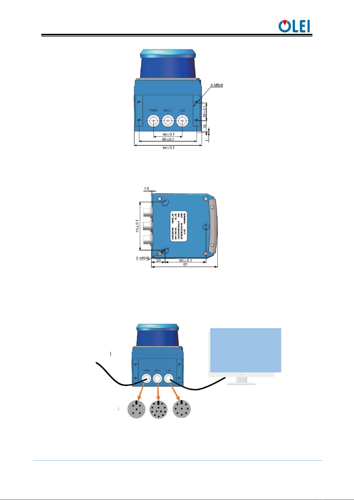
4.1 Mechanical interface...............................................................................................................................................1
4.2 Pin and wire color assignments............................................................................................................................2
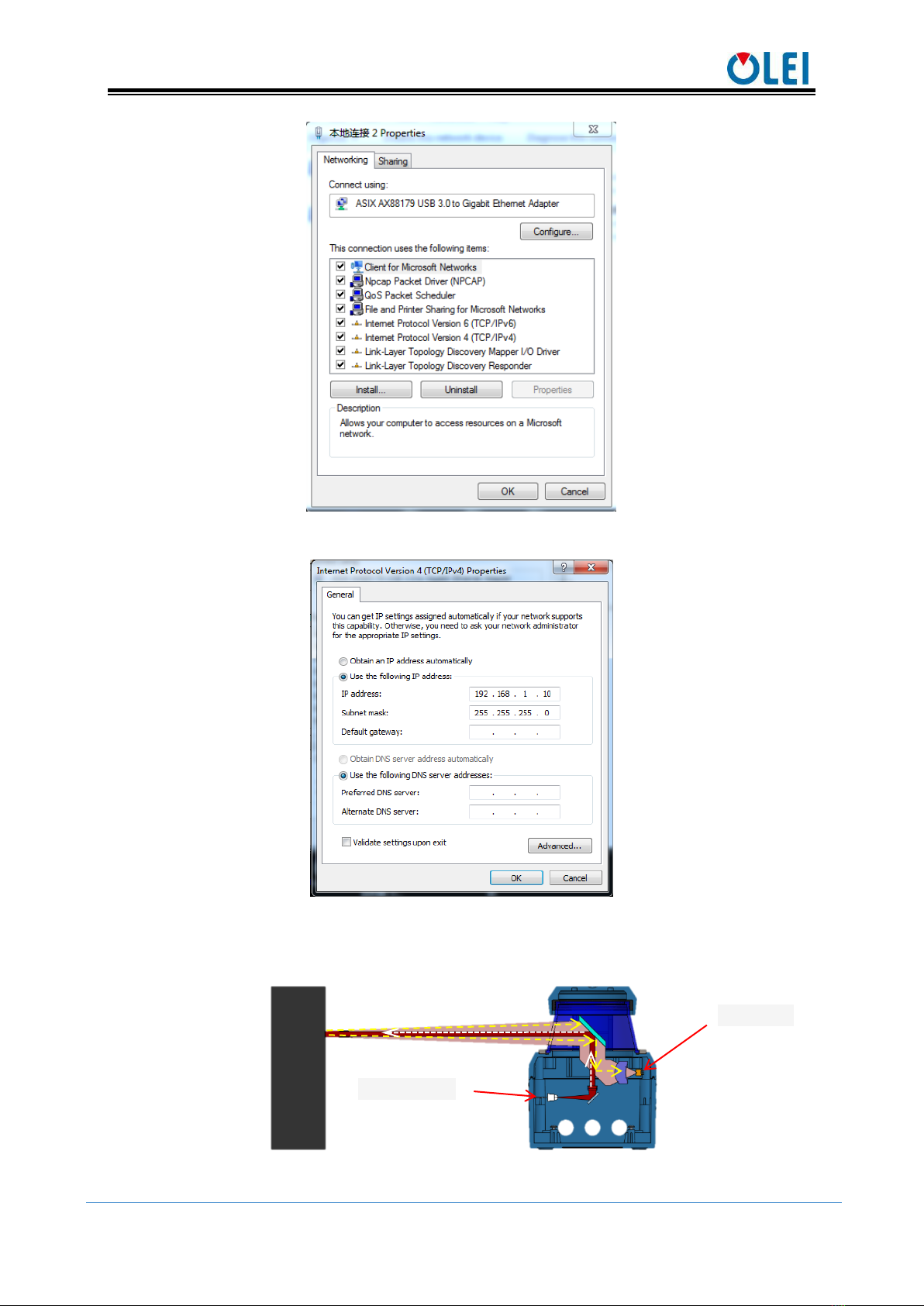
4.3 Communication interface.......................................................................................................................................4
5Measurement principle................................................................................................................................................5
6Data packet format.......................................................................................................................................................6
6.1 Overview ...................................................................................................................................................................6
6.2 Definition of Header ...............................................................................................................................................6
6.3 Definition of Data Block........................................................................................................................................7
6.4 Data conversion........................................................................................................................................................7
7Parameter configuration..............................................................................................................................................8
7.1 Parameter configuration of web page .................................................................................................................8
7.2 Configuration of OlamViewer..............................................................................................................................9
8Troubleshooting......................................................................................................................................................... 10
Appendix A Data packet ................................................................................................................................................... 11
Appendix B Mechanical Dimensions......................................................................................................................... 12
Appendix C Example of Electrical Connection....................................................................................................... 13
Appendix D Firmware Upgrade .................................................................................................................................. 13
Appendix E ROS Drive ................................................................................................................................................. 14
Appendix F Suggestions on Mechanical Installation ............................................................................................. 15
Appendix G Cleaning of sensor................................................................................................................................... 17
G.1 Notice........................................................................................................................................................................... 17
G.2 Materials required....................................................................................................................................................... 17
G.3 Cleaning method......................................................................................................................................................... 17

User Manual LR-1F
OMEN-1F-202012
1
1About this documen
This document summarizes supplementary information on mounting and electrical
installation as well as measured value output format of the LR-1F. It is aimed at sufficiently
qualified personnel for the purposes of installation, commissioning and further data processing.
Notes on commissioning, configuration and maintenance can be found in the LR-1F operating
instructions
2Safety information
Read the notes on mounting and electrical installation before carrying out these tasks;
Read additionally the LR-1F operating instructions to familiarize yourself with the
device and its functions;
The LR-1F complies with laser class 1.
Only use the device in permissible ambient conditions (e.g. temperature, ground potential).
Any applicable legal regulations or regulations of other authorities will have to be observed
during operation.
Opening the screws of the LiDAR housing will invalidate any warranty claims against
OLEI.
Repairs may only be performed on the LiDAR by trained and authorized OLEI service
personnel
3Product introduction
LR-1F is a 360° continuous scanning LiDAR. It not only provides a full-angle scanning
range, but also obtains a longer measuring distance due to optimized optical design.
LR-1F has been widely applied to industries robot obstacle avoidance, safety monitoring, industrial
automation, and intelligent logistics, etc., and can also be used for spatial surveying and mapping
systems such as mobile surveying and mapping. Users can choose different LiDAR products
according to different requirements on environmental perception and navigation.
With industry-leading manufacturing facilities, professional-level calibration laboratory,
and rigorous verification process, OLEI strives to provide users with a reliable, high-quality,
durable LiDAR.
4Installation and operation
4.1 Mechanical interface
The LiDAR can be installed in two ways: back-mounted and bottom-mounted.
Back-mounted
There are four M5 screw holes (hole depth is 8mm) at the back of the LiDAR.

User Manual LR-1F
OMEN-1F-202012
2
Figure 1 Back mounting interface of LR-1F
Bottom-mounted
There are three M5 screw holes (hole depth is 8mm) at the bottom of the LiDAR.
Figure 2 Bottom mounting interface of LR-1F
4.2 Pin and wire color assignments
LR-1F is equipped with 3 interfaces, namely power supply interface, I/O interface and 4
PIN Ethernet interface.
Figure 3 Diagram of electrical interface
Power(12~32DC)
Ethernet(RJ-45)
Power
interface
IO
interface
Ethernet
interface
Male:
Net config of PC
DHCP:off
IP: 192.168.1.10
Mask:255.255.255.0

User Manual LR-1F
OMEN-1F-202012
3
Power interface
The power interface adopts 12~32VDC power supply
NO.
Definition
Cable color
1
GND
black
2
GND
gray
3
NC
blue
4
NC
white
5
VCC(12~32VDC)
brown/red
Table 1 Definition of power interface
Figure 4 Diagram of power interface
I/O interface
NO.
Definition
Cable color
1
NC
orange
2
Output 0
orange
3
NC
yellow
4
NC
green
5
NC
purple
6
NC
gray
7
NC
dark blue
8
NC
light blue
9
NC
white
10
GND_IO
black
11
NC
pink
12
VCC_IO
red
Table 2 Definition of I/O interface
Figure 5 Diagram of I/O interface
Ethernet interface
NO.
definition
1
TxData+:Send +
2
TxData-:send-
3
RxData+:Receive+
4
NC
5
NC
Male:
Female:
Male:
Female:

User Manual LR-1F
OMEN-1F-202012
4
NO.
definition
6
RxData-:receive-
7
NC
8
NC
Table 3 Definition of Ethernet interface
Figure 6 Diagram of Ethernet interface
4.3 Communication interface
The LR-1F is connected to the computer by a RJ-45 Ethernet interface. The computer IP
address should be set up before communication. The LiDAR and computer IP must be set up in
the same subnet without any conflict. The host port is 2368 by default.
The factory default settings are as follows
Computer IP:192.168.1.10
Computer subnet mask:255.255.255.0
The default factory settings of LiDAR are as follows
Lidar IP:192.168.1.100
Lidar subnet mask:255.255.255.0
The operation steps are as follows
Figure 7 Step 1 of computer IP setting
Female:
Male:

User Manual LR-1F
OMEN-1F-202012
5
Figure 8 Step 2 of computer IP setting
Figure 9 Step 3 of computer IP setting
5Measurement principle
Figure 10 Diagram of LR-1F LiDAR work principle
Laser diode
Detector

User Manual LR-1F
OMEN-1F-202012
6
As is shown in the figure above, LR-1F measures distance by using the time-of-flight
principle. The LiDAR emits pulsed laser beams using a laser diode. If one of these laser pulses
hits an object or a person, this is reflected at its surface. The reflection is detected in the LiDAR's
receiver by a photodiode. The LiDAR calculates the distance to the object from the transit time
required by the light from emission of the beam to receipt of the reflection. The calculation
method is as follows:
𝐷 = 𝐶𝑇
2
D—Detection distance
T—Flight time
C—Speed of light
6Data packet format
LR-1F can realize laser point cloud data transmission. Please refer to the following for the
analysis of LiDAR point cloud data.
The information transmission between LR-1F and the computer follows UDP standard
network protocol. The data adopts the Little-endian format,the low byte is in the front,and the
high byte is in the back.
6.1 Overview
Total length of data packet is 1240 bytes, among which header accounts for 40 bytes, data
returned by laser is 1200 bytes.
Figure 11 Format of point cloud information packet
The total length of the data frame is 1240 bytes, among which:
Frame header: 40 bytes.
Data block: 150×8=1200 bytes.
6.2 Definition of Header
Total length of data packet is 1240 bytes, among which header accounts for 40 bytes, data
returned by laser is 1200 bytes.
Offset
Length
Description
0
4
Identifier, fixed as 0xFEF0010F
4
2
Protocol version, currently 0x0200
6
1
Distance ratio, actual distance value = distance reading ×distance ratio (mm)
7
3
Brand code, indicate with capitalized letters and numbers, fill in with ‘\0’ in the
end if isn’t long enough.
10
12
Sales model string ending with ’\0’

User Manual LR-1F
OMEN-1F-202012
7
Offset
Length
Description
22
2
Internal model code
24
2
Hardware version
26
2
Software version
28
4
Timestamp, unit: ms
32
2
Bit[14:0]: Rotation rate
BIT 15:rotation direction(0:clockwise,1:anticlockwise)
34
1
Safe zone status, same as status of the hardware INPUT/OUTPUT
BIT[3:0]: Same as OUTPUT[3:0]
BIT[7:4]: Same as INPUT[3:0]
35
1
Error status, the corresponding position is “1”, indicates an error
BIT0: Motor fault,
BIT1: Power fault,
BIT2: Temperature fault
36
4
Reserved (detailed meaning to be determined)
Table 4 Definition of header file
6.3 Definition of Data Block
Total length of data packet is 1240 bytes, among which header accounts for 40 bytes, data
returned by laser is 1200 bytes.
Table 5 Definition of data block
6.4 Data conversion
6.4.1 Angle calculation
Details on calculating angle of LR-1F is shown as below:
1) Obtain angle value:0xaa & 0x1d
2) Interchange of high bits and low bits:0x1d & 0xaa
3) Combine into an unsigned hexadecimal number:0x1daa
4) Convert to decimal:7594
5) Multiply by minimum resolution:0.01°
6) Result:75.94°
Offset
Length
Description
0
2
Angle,unsigned integer,valid range:0~35999
Unit :0.01°/LSB,indicating range:0°~359.99°
Note:If this value is greater than or equalto 0xFF00, thenthis blockis invalid
and must be ignored.
2
2
Distance reading, unsigned integer.
The measured distance is determined by the distance ratio of the header, that
is, measured distance="the reading value ×the distance ratio of the packet
header" (unit: mm).
4
2
Signal strength indicates the strength of the received signal, ranging from 0
to 65535.
6
2
Reserved (detailed meaning to be determined)

User Manual LR-1F
OMEN-1F-202012
8
6.4.2 Distance calculation
Details on calculating distance of LR-1F is shown as below:
1) Obtain distance value:0x11 & 0x12
2) Interchange of high bits and low bits:0x12 & 0x11
3) Combine into an unsigned hexadecimal number:0x1211
4) Convert to decimal:4625
5) Multiply by distance ration:suppose distance ration is 1mm
6) Result:4625mm
6.4.3 Calculation of signal strength
The signal strength calculation method of LR-1F is shown in the following example:
1) Obtain the signal strength value: 0x11 & 0x12
2) Interchange of high bits and low bits: 0x12 & 0x11
3) Combine into an unsigned hexadecimal number: 0x1211
4) Converted to decimal number: 4625
5) Results: 4625
7Parameter configuration
7.1 Parameter configuration of web page
Web page parameter configuration method of LR-1F is as follows:
Open the browser (please use Chrome,Firefox, Edge or other standard browsers), and
enter the LiDAR IP address;
"Model" and "Version" at the top of the UI indicate the product model and firmware
version;
"Temperature", "Voltage" on the right side of the UI are the LiDAR parameters displayed
in real time, indicating the temperature and voltage. When the font color of parameter turns
red, please check whether the LiDAR is malfunctioning;
Automatically read the current settings of LiDAR by refreshing the page;
Select the desired speed through "Motor RPM": 600/900/1200/1500
(The corresponding scanning frequency is 10/15/20/25HZ ), and click "SetConfigs" to confirm;
Set the offset of the LiDAR's 0 degree angle through "Angle offset";
Enable/disable the DHCP function: the LiDAR dynamically obtains an IP address from
the DHCP server (ON), and the LiDAR needs to set up a static IP address (OFF);
Modification of LiDAR IP: Host IP and the LiDAR IP should be in the same network
segment, click the "Set Network" to confirm, and the modification is complete after the
LiDAR is powered on again.

User Manual LR-1F
OMEN-1F-202012
9
Figure 12 Parameter configuration of web page
7.2 Configuration of OlamViewer
The OlamViewer interface is shown as following. Please refer to OlamViewer software
manual for detail.
Figure 13 Sample of The OlamViewer interface
The Web page setting interface and The OlamViewer interface may change due to
continuous update of products and is subject to actual content.

User Manual LR-1F
OMEN-1F-202012
10
8Troubleshooting
Problem
Method
LiDAR fails to scan
Verify whether the power supply is properly connected
Verify whether the power voltage meets 12~32VDC
Please contact OLEI if the above conditions are normal.
LiDAR scan
produces no data
Verify whether the network connection is normal
Verify whether the IP settings on the data receiver are correct.
Try to use third-party data scraping software to verify whether data could be
obtained normally
Verify whether only one LiDAR software is enabled.
Verify whether firewall of the data receiver is disabled or if there are other
security software or processes blocking data transmission.
Please contact OLEI if the above conditions are normal.
Table 6 Troubleshooting

User Manual LR-1F
OMEN-1F-202012
11
Appendix A Data packet

User Manual LR-1F
OMEN-1F-202012
12
Appendix B Mechanical Dimensions

User Manual LR-1F
OMEN-1F-202012
13
Appendix C Example of Electrical Connection
OUTPUT
Appendix D Firmware Upgrade
This appendix will explain how to use LidarUpgrade2D to upgrade the firmware version
of the LR-1F series LiDAR.
Figure 14 Icon
D.1 Function of software
For 2D LiDAR LR-1F series firmware upgrade
D.2 Surroundings for software
- Windows 7,8,10
- .Net framework 4.5.2
D.3 Software operation
-1. Connect the LiDAR correctly. Check whether the LiDAR communication is normal.
-2. Click the File Information box or drag the firmware file in. The relevant information of the
corresponding firmware is prompted after the firmware file is correctly loaded.

User Manual LR-1F
OMEN-1F-202012
14
Figure 15 Interface of software upgrade
-3. Clicking the"Upgrade",restart the LiDAR power, the file will be downloaded to the LiDAR
automatically.
-4. Check the"Continuous mode", after the upgrade, it will automatically wait for the next
upgrade, which can be used to upgrade LiDAR firmware in batches.
Appendix E ROS Drive
One-key script of 2D LiDAR ROS drive:
wget http://cn.ole-systems.com/sh/ole2d.sh
chmod -R 777 ole2d.sh&&./ole2d.sh
Note: shell script will be automatically downloaded to the latest version of ROS1.0 from
the company's official website, and will be built, compiled, run and demonstrated in rviz
with one-key.
build
1. make catkin workspace at your ROS machine
> mkdir -p ole2d_ws
2. copy 'src' to ole2d_ws
>cp src ole2d_ws
3. install depend
>rosdep install --from-paths src --ignore-src --rosdistro kinetic -y
4. build
>chmod -R 777 src
>catkin_make
Note: before compiling, please "chmod" commond give executable permission to "src" folder.
run
1. source to path
>source devel/setup.bash
2. new terminal,then run roscore
>roscore
3. connect LiDAR and host,LiDAR IP default 192.168.1.100,port default 2368
Note that you must change the Internet address and netmask.
host IP default 192.168.1.10,netmask default 255.255.255.0

User Manual LR-1F
OMEN-1F-202012
15
these IP and port can be modified by vendor config software
4. run LiDAR drive at first terminal
>roslaunch olelidar scan.launch
rviz view
1. new terminal,then run rviz
>rosrun rviz rviz -f olelidar
2. at rviz,add topic olelidar/scan/LaserScan
Appendix F Suggestions on Mechanical Installation
When installing LiDAR, pay attention to the following points:
1. Please remove the transparent protective film on the window when using it on site.
2. Make it as immune to shock and vibration as possible..
3. So that it is not exposed to any direct sunlight (window, skylight) or any other heat sources.
to prevent the internal temperature of the device from rising.
4. It is recommended that the mounting base used to fix the LiDAR be as flat as possible.
5. The positioning column on the mounting base should strictly follow the depth of the
positioning column at the bottom of the LiDAR, and should not be higher than 4mm. It is
recommended to use aluminum alloy mounting base for better heatdissipation .
6. When installing the LiDAR, if the LiDAR has contact mounting surfaces on both top and
bottom, please make sure that the distance between the mounting surfaces is greater than the
height of the LiDAR to avoid squeezing.
7. The tilt angle should not exceed 90 degrees when the LiDAR is installed.Excessive tilt angle
will affect the life of the LiDAR.
8. When arrange the wiring of the LiDAR, wiring on the LiDAR should not be too tight; keep
the wiring loose.
In order to avoid any influence to the measurement accuracy due to mutual interference
between LiDARs, we recommend the following installation. (Α≥6°, H≥200mm, the position of
the line segment in the diagram represents the LiDAR emission position)
Figure 16 Placement of two LiDARs opposed to each other
Figure 17 Crosswise placement of two LiDARs

User Manual LR-1F
OMEN-1F-202012
16
Figure 18 Placement of two LiDARs with parallel offset
Figure 19 Placement of two LiDARs with parallel offset, one of these upside down
Figure 20 Placement of two LiDARs upside down, parallel offset
Figure 21 Placement of two LiDARs with parallel offset, one of these upside down

User Manual LR-1F
OMEN-1F-202012
17
The emission position of the 2D LiDAR from the reference plane is as follows:
Figure 22 Light emission position of LR-1BS, LR-1B, LR-1F
Appendix G Cleaning of sensor
OLE-LiDAR, especially the ring-shaped protective cover, should be kept clean in order to
accurately sense the surrounding environment.
G.1 Notice
Please read Appendix E thoroughly and carefully before cleaning OLE-LiDAR, otherwise
improper operation may damage the equipment.
G.2 Materials required
1. Clean fiber cloth
2. Neutral soap spray
3. Clean water spray
4. Isopropanol solvent
5. Clean gloves
G.3 Cleaning method
If there are only some dust on the surface of the LiDAR, directly use a clean fiber cloth
with a small amount of isopropyl alcohol solution to gently wipe the surface of the LiDAR, and
then wipe it with a dry and clean fiber cloth.
If there are mud or other blocky foreign matter on the surface of LiDAR, first spray clean
water on the surface of the dirty part on the LiDAR to remove the mud and other foreign matter
(Note: please do not wipe off the mud directly with a fiber cloth, as this may scratch the surface,
especially the surface of the protective cover). Then spray with soapy water on the dirty parts,
since the lubricating effect of soapy water could accelerate the separation of foreign materials.
Gently wipe the surface of the LiDAR with a fiber cloth, be careful not to scratch the surface.
Finally, clean the soap residue on the LiDAR surface with clean water (if there are still residues
stains on the surface, use an isopropyl alcohol solution to clean it again), and wipe it with a dry
microfiber cloth.
.
Other manuals for LR-1F Series
1
Table of contents
Other OLEI Accessories manuals
Popular Accessories manuals by other brands

Huawei
Huawei FusionCol8000-E260 quick guide

ROSE DISPLAYS
ROSE DISPLAYS ANOMULTI ROUND WITH CABLE AND SAUCER instruction sheet

Fencing SmartBox
Fencing SmartBox SmartBox user manual

PCB Piezotronics
PCB Piezotronics 260A11 Installation and operating manual

Beper
Beper P203TFO110 manual

Hioki
Hioki CT9555 instruction manual

Winland Electronics
Winland Electronics HUMID-ALERT HA-III+ quick start guide

SVAT
SVAT VIS101-TX instruction manual

Browan
Browan TBWL100-915 Reference manual

LEGRAND
LEGRAND Celiane 673 13 quick start guide

OPTEX FA
OPTEX FA FASTUS TOF-DL250 Series instruction manual

DYNATEK
DYNATEK Dyna 4000 Pro User instructions