Oliver 1308-C Operation instructions

1308S20000CV1
Grand Rapids, Michigan, U.S.A. 49504-5298
USER’S OPERATING AND INSTRUCTION MANUAL
MODEL 1308-C & 1308-N
HEAT SEALER

1308S20012 0-1
INDEX
Section Description Document No. Page No.
DESCRIPTION/SPECIFICATIONS ----------------------------1308S20013 ------------------------- 1-1
Description ------------------------------------------------------------------------------------------------- 1-1
Specifications----------------------------------------------------------------------------------------------- 1-1
GENERAL SAFETY INSTRUCTIONS-------------------------1308S20014-------------------------- 2-1
Lockout-Tag out-------------------------------------------------------------------------------------------- 2-1
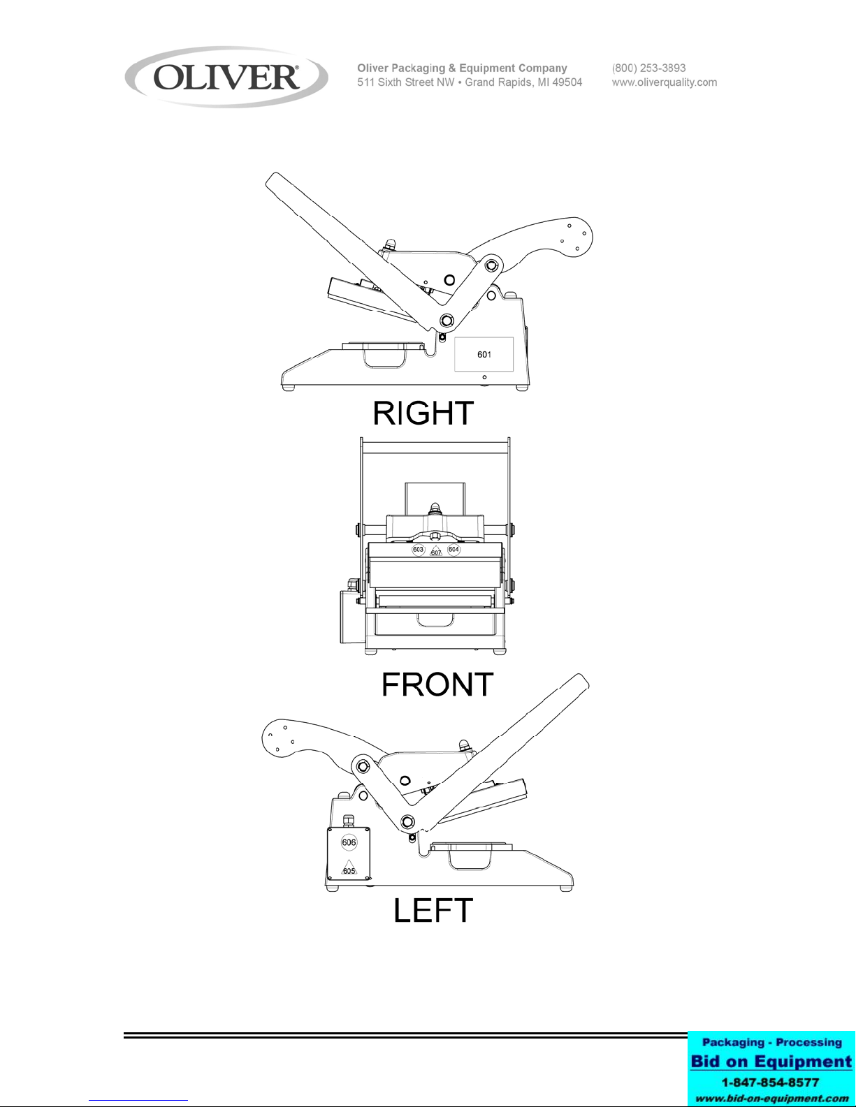
NAMEPLATE/PICTOGRAMS PART LIST--------------------1308S20015-------------------------- 3-1
Nameplate/Pictogram Locations by Item Number------------------------------------------------ 3-2
SETUP AND OPERATION GUIDE-----------------------------1308S20036-------------------------- 4-1
Set up continued------------------------------------------------------------------------------------------- 4-2
OPERATING PROCEDURES-----------------------------------1308S20017--------------------------- 5-1
Adjustment and Quality ---------------------------------------------------------------------------------- 5-2
TECHNICAL SPECIFICATIONS------------------------------- 1308S20018--------------------------- 6-1
CLEANING PROCEDURES-------------------------------------1308S20019----------------------------7-1
Cleaning Procedures--------------------------------------------------------------------------------------7-2
Cleaning Cutter Blade------------------------------------------------------------------------------------ 7-2
Replacing and Checking Gaskets----------------------------------------------------------------------7-3
Disposal Procedure----------------------------------------------------------------------------------------7-3
TROUBLE SHOOTING---------------------------------------------1308S20020---------------------------8-1
WIRING DIAGRAM--------------------------------------------------1308S20021---------------------------9-1
1308-C HEAT SEALER---------------------------------------------1308S20022--------------------------10-1
1308 Heat Sealer Parts Lists----------------------------------------------------------------------------10-2
1308 Heat Sealer Parts Lists Con’t--------------------------------------------------------------------10-3
1308 Tray Carrier-------------------------------------------------------------------------------------------10-4
1308 Tray Carrier Parts List------- ----------------------------------------------------------------------10-4
WARRANTY ------------------------------------------------------- GEN 050816
WARRANTY PROCEDURE------------------------------------ GEN 050817
RETURNED PARTS POLICY --------------------------------- GEN 050818
REV. 1/26/09

1308S20013 1-1
DESCRIPTION/SPECIFICATIONS
Description
The Oliver Model 1308 Heat Sealer is designed and manufactured to ensure a user
friendly operation of producing film lidded trays with a cost effective approach.
The manually operated machine operates with either a 120 or 230 V.A.C. outlet. The
machine was designed to be compact to limit the amount of table space needed to
operate.
Specifications
Space Requirements, (Shown with standard options)
Model 1308-C & 1308-N (All dimensions are shown approximate)
Shipping Weight – 65 lbs (30 Kg) (approximate)
Net Weight – 60 lbs (27 Kg) (approximate)

1308S20014 2-1
GENERAL SAFETY INSTRUCTIONS
WARNING
IT IS ESSENTIAL THAT ALL OPERATORS AND MAINTENANCE PERSONNEL
OBSERVE THE FOLLOWING SAFETY PRECAUTIONS. IMPROPER
INSTALLATION, MAINTENANCE, OR OPERATION OF THIS EQUIPMENT
MAY CAUSE SERIOUS INJURY.
1. Read this manual before attempting to operate your heat sealer. Never allow an
untrained person to operate or service this unit.
2. Observe all caution and warning labels affixed to the machine.
3. Always unplug the machine before cleaning or servicing.
4. Do not submerge in water. Do not hose down.
5. Use original replacement parts.
6. Wear proper, personal, protective, safety equipment if necessary.
7. Keep hands away from moving parts of the machine while it is operating.
8. In addition to these general safety instructions, please follow the more specific safety
instructions provided throughout the rest of this operating and instruction manual.
WARNING
DO NOT USE FOR OTHER THAN ORIGINALLY INTENDED PURPOSE.
LOCKOUT-TAGOUT
It is very important that the unit should be free of any unexpected energization, or be
able to release hazardous energy during service or maintenance activities. Therefore,
always switch the machine off before unplugging the power cord from BOTH the unit
and the wall.

1308S20015 3-1
NAMEPLATE/PICTOGRAM PARTS LIST
(INTERNATIONAL MODELS ONLY)
ITEM NO PART DESCRIPTION PART NUMBER
601
VOLTAGE CYCLE PHASE AMPS
MODEL NO. SERIAL NO.
KW MFG’D MASS
Spurkt 3
35804 AR Venray,
The Netherlands
PRODUCTS BV
BAKERY
“OLIVER” 6401-5076
603 “STAY CLEAR” 6401-9043
604 “CONSULT OPERATORS…..” 6400-3039
605 “ELECTRICAL SHOCK” 6400-5009
606 “UNPLUG BEFORE OPENING” 6402-1028
607 “HOT SURFACE” 6400-8021
**SEE SHEET 3-2 FOR NAMEPLATE LOCATIONS BY ITEM NUMBER

1308S20015 3-2
NAMEPLATE/PICTOGRAM LOCATIONS BY ITEM NUMBER

1308S20034 3 - 1
1308 SETUP & OPERATION GUIDE
Remove the 1308 UnitShipping carton
Place the 1308 Unit on
a table or cart
Open carton as shown
Remove parts and packing
material
Snip the plastic ties on
the electrical cord
Install Counterweight
Step One
Step Two Step Three

1308S20034 3 - 2
Step Four Install the two
counterweight holders and
plastic knobs
Install holder
Step One
Install Plastic Knob and
tighten
Install holder and knob
on other side
Install Holder
Step One
Install Plastic Knob and
tighten
Step Two
Showing the
counterweight installed

1308S20034 3 - 3
Hold down on the handle
and remove the strap
Lift Handle Handle shown in the
upright position
Install power cord plug
as shown
Plug power cord in 115V
wall socket
With handle in the upright
position push in on the
rocker switch to the “I”
position (POWER ON)
Allow 30 minutes for the
heater platen to heat up to
temperature
Install tray carrier
Step One
Using the locating pins in
the tray carrier and holes in
the frame as shown

1308S20034 3 - 4
Install film roll in back of
unit
Pull the film from the top
of the roll towards the front
of the unit
Placing it between the two
white
g
uide rollers
Pull the film from the top
of the roll
Lift up the black film pinch
roller and slid the film
under it as shown
Place a tray in the tray
carrier
Pull the film forward ¼”
beyond edge of tray
Using both hands pull
the handle down
Pull the handle down all
the way to this position and
hold it down for ½ to 1
seconds
The film is cut at this time
Lift handle to the
upright position
Remove the sealed tray
Shown in the upright
position ready to seal
another tray

1308S20017 5-1
OPERATING PROCEDURES
1. Plug the power cord into a properly grounded outlet. Avoid the use of extension
cords.
2. Pusher rocker switch to “On” position (red light indicates on).
NOTE: It should take approximately 15 minutes for the machine to warm up to
operating temperature.
3. Place tray carrier in its designated area with the dowel pins facing down
4. Place filled tray in tray carrier. Make sure the food in the tray is not higher than
the flange of the tray
5. Grasp the corners of the film and pull it straight across the tray going a ¼ inch
past the flange of the tray
6. Pull handle down with both hands until it stops. Hold the handle down for
approximately 2 seconds.
7. Lift the handle to its upright position.
8. Remove tray from tray carrier.
9. Repeat steps 4 thru 8
CAUTION
IT IS NOT RECOMMENDED TO LEAVE THE MACHINE ON WHEN IT WILL BE OUT
OF OPERATION FOR AN EXTENDED PERIOD OF TIME.
Rev 2-24-09

1308S20017 5-2
ADJUSTMENT AND QUALITY
Your OLIVER Model 1308 was tested at the factory using Oliver trays and film.
NOTE
•THE TEMPERATURE CANNOT BE ADJUSTED BY THE OPERTATOR
The heater platen temperature is factory set at approximately 300°F (Approx. 150°C).
Contact the Oliver Service Department if you suspect the heated platen temperature is
not correct.
It is necessary to periodically check for a proper seal. This can be done by pull the film
over an empty tray carrier, sealing it like normal and peeling the film. If there is a proper
seal, the pattern on the film should be a complete outline of gasket material provided.
A poor seal will occur if the product in the tray contaminates the tray flange or the
pressure generated by the sealing mechanism is less than 15lbs. The pressure can be
adjusted by removing the acorn nut atop the center arm and giving a few turns to the nut
on the heater adjustment bolt. This will expose more threads between the casting and
the sealing mechanism, therefore, generating more pressure.
Under different operating conditions, it may be necessary to increase or decrease the
sealing time. This is done by varying the length of time the operating handle is in the
down position. Holding the handle down longer makes the seals stronger. Although a
stronger seal may cause shredding or tearing of the film when removing film from tray.

1308S20016 4-1
BASIC MACHINE COMPONENTS AND SET UP
Before proceeding further, take a moment to familiarize yourself with the identification of
the machine components as shown in the illustration below.
SET UP
1. Carefully remove the Model 1308 from the box. Check to make sure the order is
complete, and it has not been damaged during shipment.
2. Place the unit in a suitable location which provides an adequate working space.
The location must be sturdy, level, and capable of holding 60lbs. per machine.
3. Remove all packaging materials and shipping restraints such as plastic ties and
tape.
4. Raise the handle to full extension.
5. Place film roll in designated area towards the rear of the unit.
6. Thread film through the film pinch roller as shown below.

1308S20016 4-2
SET UP CONTIUED
NOTE:
FILM SUPPLIED BY OLIVER PRODUCTS COMPANY IS WOUND WITH THE
ADHEASIVE SIDE IN. FEED FILM FROM THE TOP OF THE ROLL AS SHOWN.

1308S20019 7-1
CLEANING AND MAINTENANCE
NOTE
•These cleaning recommendations are not meant to replace plant standard
manufacturing procedures or regulatory requirements.
•If the machine has been in operation, allow the unit to cool before cleaning.
•Do not submerge unit in water. Do not wash down.
•Tray carrier is NOT recommended for automatic dishwashers
CAUTION
•CAUTION HOT: The heated platen is HOT! Caution must be used to prevent
injury from heated platen.
WARNING
•Make sure the unit has been unplugged for a minimum one hour before cleaning.
•It is important that the surface of the heater platen is kept clean and smooth.
Regularly clean the OLIVER Model 1308 with a mild cleaner and a damp cloth. If
food product comes in contact with the surface of the platen, it tends to burn on
and become hard. This results in an irregular surface on the face of the platen
which can result in poor seals. If this happens, it will be necessary to remove this
contaminate material. When cleaning care must be taken to avoid scratching or
gouging the surface of the platen. DO NOT SCRAPE THE SURFACE OF THE
PLATEN WITH SHARP OBJECTS AND AVOID THE USE OF METAL TOOLS.
The use of plastic or soft-metal scouring pads such as SCOTCH BRITE™ or
CHORE BOY® provides a safe and effective means of cleaning the platen. Be
sure to wipe all surfaces with a sanitizing agent after cleaning.
CAUTION
IF CLEANING THE HEATER PLATEN WHILE THE UNIT IS STILL ON, MAKE SURE
THAT HAND PROTECTION IS WORN AT ALL TIMES TO PREVENT SKIN CONTACT.

1308S20019 7-2
CLEANING AND MAINTENANCE CONTINUED
CLEANING PROCEDURES
1. Unplug the unit and allow one hour for cooling.
2. Remove tray carrier.
3. Place tray carrier in the dishwasher or wipe down with a standard cleaning
solution.
4. Lift operating handle to expose the bottom side of the heater, and then wipe
off the heater platen.
5. Use a sanitizing solution to spray and wipe down the rest of the unit.
6. Replace tray carrier
NOTE
THE DELRIN LINKS LOCATED ATOP THE UNIT SHOULD BE LUBRICATED WITH A
FOOD GRADE MATERIAL ONCE A MONTH TO PREVENT WEARING.
CLEANING THE CUTTER BLADE
1. Lift handle up to its resting position.
2. Use a damp cloth with sanitizing solution to wipe off any access food particles
located on the back of the cutter blade.
CAUTION
THE CUTTER BLADE IS SHARP. USE A PROTECTIVE GLOVE TO DO THIS
CLEAING OPERATION. FAILURE TO DO SO MAY RESULT IN SERIOUS INJURY.

1308S20019 7-3
CLEANING AND MAINTENANCE CONTINUED
REPLACING AND CHECKING GASKETS
•If there are any gouges, cuts or gaps in the gasket, the gasket will have to be
replaced.
•Be sure to replace all the gaskets not just the piece that is damaged.
•When reinstalling gaskets, the gasket must be seated all the way down in the
groove.
•Do not stretch gasket when reinstalling.
•After the new gaskets are installed, place the tray carrier up side down on a flat
surface and check to see if the newly installed gasket is even.
•If not even, depress or lift gasket to provide an even heat sealing surface.
•It is necessary to periodically check for a proper seal. This can be done by pull
the film over the empty tray carrier, sealing it like normal and pulling the film. If
there is a proper seal, the pattern on the film should be a complete outline of the
edges of the tray.
DISPOSAL PROCEDURE
When considering disposing of your unit, please contact local authorities for any special
instructions.

1308S20021 9-1
WIRING DIAGRAM
1-60-120V
REF. W/D 1308C12002
1-60-230V
REF. W/D 1308C12000

1308S20022 10-1
MODEL 1308 HEAT SEALER
Rev 8-15-09

1308S20022 10-2
MODEL 1308 HEAT SEALER PARTS LISTS
ITEM NO PART DESCRIPTION PART NUMBER______QTY
001 Base 1308-0015-301 1
002 Bumper-Rubber 5902-0035 6
003 PIN-DOWEL 1/4X3/4" STST 5835-6475 2
004 Tube-Aluminum 7/8” O.D. 4639-1414-1116 1
005 Bearing-Roll End 5252-3002 2
006 Guide-Roller Film 1908-0041 2
007 O-ring 6909-3211 2
008 Rod-Film Dispensing 1308-0018 1
009 SCREW-SOCSET CUPPT 5842-6120 4
010 Tube-Film Shaft 1308-0016 1
011 WASHER-FLAT 5851-9306 2
012 Roller-Pinch 1308-0048-1 1
013 Spacer-Pinch Roller 1308-0049-1 2
014 WASHER-FLAT 1308-0050 1
015 WASHER-#10 FLAT 5851-9302 2
016 WASHER-LOCK 5851-9394 2
017 SCREW-HEX HD 10-24 5843-1231 2
101 Arm-Center 1308-0014 1
102 Shaft-Center Arm Link 1308-0001 1
103 BEARING-SINT BRZ FLNG 5254-3215 4
104 Clip-E Style (3/4” Shaft) 5840-2841 8
105 Link-Center Arm 5502-1900 2
Rev 8-15-09
This manual suits for next models
1
Table of contents
Other Oliver Food Saver manuals
Popular Food Saver manuals by other brands

IPG
IPG Interpack USA 3036-SB Operator's manual & parts list

FoodSaver
FoodSaver VS1200 Series quick start guide

siat
siat SM44 HS Instruction manual and spare parts list

CASO DESIGN
CASO DESIGN VRH 590 advanced instruction manual

TIGMON
TIGMON Lauben 10WT user manual

Heat Seal
Heat Seal 625A MINI Operating & service parts manual