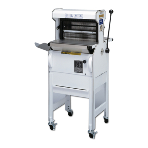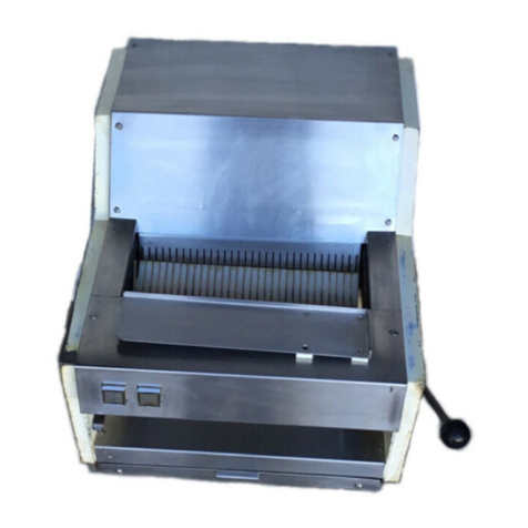
MODEL 709 MINI SUPREME BREAD SLICER
0709S20029-2
•Slices Vary In Thickness: (Cont’d.):
At this point check the side to side movement of the lower blade frame: it should be at
the minimum which still allows free travel in the tracks. If the side to side movement
seems satisfactory check the centering of the frame. The distance from the side of the
blade frame to the machine’s side should be as close as possible to the same distance
on each side.
Should either of the above two situations need correction loosen the four nuts, two on
each side, which secure the lower blade frame guide bars, (they are accessible from the
underside of the blade frame). Once loosened, the blade frame can be centered in the
machine, making sure that the guide bars are as far into the tracks as they will go, thus
limiting side to side movement. When the bars are as far into the tracks as reasonably
possible and the blade frame is centered in the machine, re-tighten the nuts. Re-check
the blade frame for proper centering, side to side movement and ease of travel.
When the lower blade frame has been found to be in its proper position, or, corrected to
the proper position, (if that was required), as described previously, re-install the upper
blade frame. Replace the shoulder screw and link at the foot of the blade frame,
replacing and tightening the nut and lock washer which secure the shoulder screw.
Check the distance between any three adjacent blades using a 12 inch or shorter ruler.
the outside blades should be the same distance from the center blade. If this is the case
the slices will be the same thickness, if the distance varies then the upper blade frame
must be adjusted side to side until the measured distances are equal.
To adjust the upper blade frame loosen the four nuts, (two on each side), which secure
the blade frame guide bars. Once loosened the blade frame can be adjusted by moving
it slightly either right or left in the machine until the distances as measured above are
equal. Make sure the guide bars are as far into the tracks as they will go to limit side to
side movement. When the bars are as far into the tracks as possible and the blade
spacing is equal, re-tighten the nuts. Re-check the blade frame for proper spacing, side
to side movement and ease of travel.
Rotate the holddown back into the knives. Replace and secure the four mounting
screws of the pivot blocks and replace the front and top covers securing each with the
four screws which were previously removed.
•Limit Switch and Actuating Flag Adjustment:
After disconnecting the slicer from the power supply, remove the rear cover from the
machine allowing access to the limit switch area.
•Limit Switch and Actuating Flag Adjustment (Cont’d.):
