Olivetti Explora 200 User manual

Web Cash
Explor@ 200-300
SERVICE MANUAL
Code XZAC3273

PUBLICATION ISSUED BY:
Olivetti S.p.A.
Documentazione
77, Via Jervis - 10015 Ivrea (Italy)
Copyright © 2006 Olivetti
All rights reserved.
Printed in Italy at:
WARNING!
D Danger of explosion in the case of replacement with a different non-compliant type.
Replace the batteries following the instructions provided.

INDEX
1. OVERVIEW................................................................................................................................................ 1-1
1.1 INTRODUCTION............................................................................................................................. 1-1
1.2 THE SYSTEM.................................................................................................................................. 1-2
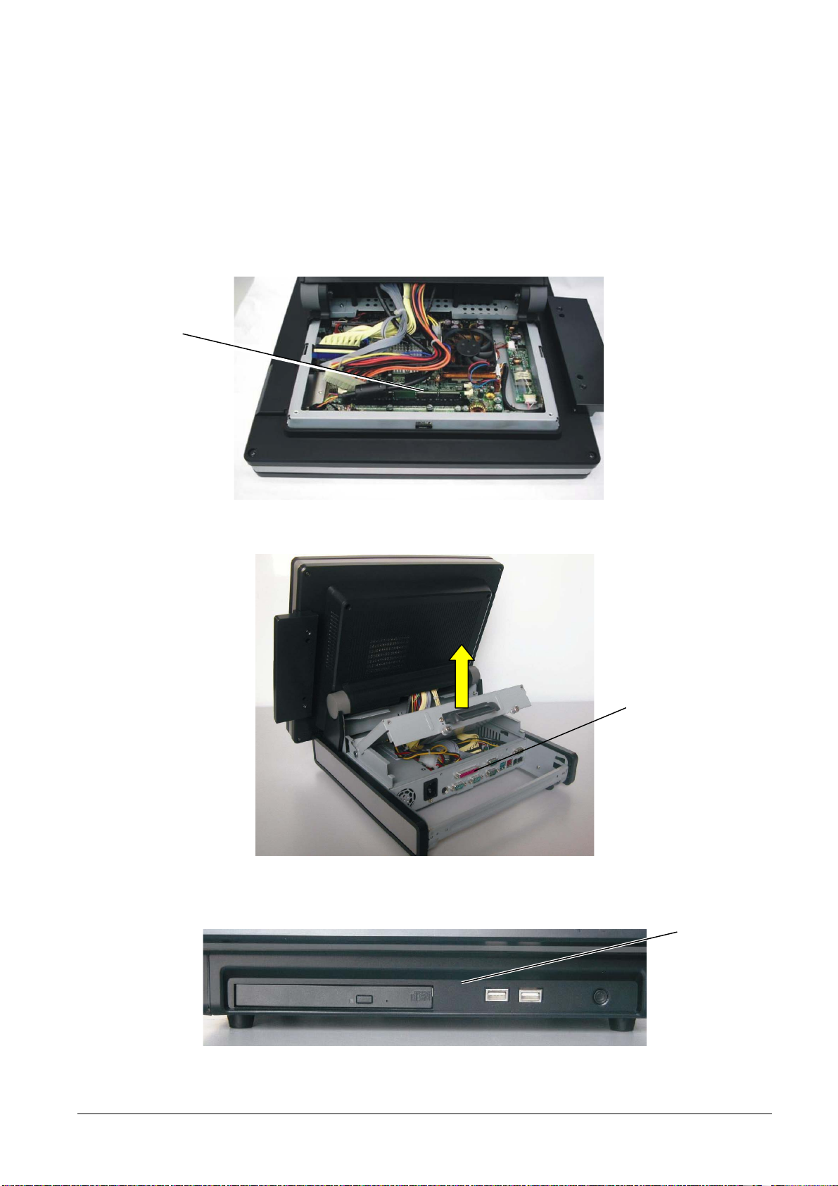
1.2.1 System – Front panel....................................................................................................... 1-3
1.2.2 System – Rear panel........................................................................................................ 1-3
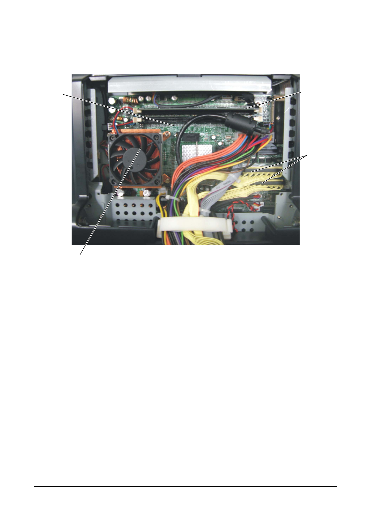
1.2.3 System – View of the inside............................................................................................. 1-4
1.2.4 System – Full view ........................................................................................................... 1-5
1.3 MOTHERBOARD ............................................................................................................................ 1-7
1.3.1 Motherboard connectors .................................................................................................. 1-8
1.3.1.1 Block diagram of motherboard connectors .................................................... 1-9
1.3.2 Motherboard jumpers ..................................................................................................... 1-10
1.3.2.1 Jumper JP1 – Compact Flash Master/Slave Setting ..................................1-10
1.3.2.2 Jumper JP5 – CMOS Operating Mode Setting...........................................1-10
1.3.2.3 Jumper JP9 – Power Mode Setting............................................................. 1-10
1.3.2.4 Jumper JP10 – CPU Frequency Setting...................................................... 1-10
1.3.2.5 Jumpers JP7 – JP8 – CPU Voltage Setting.................................................1-10
1.3.2.6 Jumper JP6 – LCD ID Setting......................................................................1-11
1.4 FRONT PANEL I/O BOARD.......................................................................................................... 1-12
1.4.1 Front panel I/O board connectors .................................................................................. 1-12
1.5 REAR PANEL I/O BOARD ............................................................................................................ 1-13
1.5.1 Rear panel I/O board connectors................................................................................... 1-13
1.5.2 Jumpers rear panel I/O board ........................................................................................ 1-14
1.5.2.1 Jumper JP1 – COM1/COM2/ Cash Drawer DC Power Setting ...................1-15
1.5.2.2 Jumper JP2 – COM3/COM4/ DC Power Setting ......................................... 1-15
1.5.2.3 Jumpers JP3 – JP4 – USB DC Power Setting............................................. 1-15
1.6 TOUCH SCREEN BOARD............................................................................................................ 1-16
1.6.1 Touch screen board connectors..................................................................................... 1-16
1.7 INVERTER BOARD....................................................................................................................... 1-16
1.7.1 Inverter board connectors ..............................................................................................1-16
1.8 BADGE READER (FIELD OPTION).............................................................................................. 1-17
1.8.1 Badge reader board ....................................................................................................... 1-17
1.8.2 Badge reader board connectors..................................................................................... 1-17
1.9 TECHNICAL DATA........................................................................................................................ 1-18
1.10 TROUBLESHOOTING................................................................................................................... 1-20
1.10.1 System errors................................................................................................................. 1-20
1.10.2 Peripheral errors............................................................................................................. 1-21
1.11 CONTROL PROCEDURES........................................................................................................... 1-23
1.11.1 Hard Disk control............................................................................................................ 1-23
1.11.2 Power supply control...................................................................................................... 1-25
1.11.3 RAM control.................................................................................................................... 1-26
2. INSTALLATION......................................................................................................................................... 2-1
2.1 INTRODUCTION............................................................................................................................. 2-1
2.1.1 General warnings............................................................................................................. 2-1
2.2 UNPACKING THE SYSTEM ........................................................................................................... 2-1
2.3 INSTALLATION OF THE HARDWARE...........................................................................................2-2
2.3.1 Rear panel........................................................................................................................ 2-2
2.3.2 Front panel....................................................................................................................... 2-2
2.4 INSTALLATION OF THE CUSTOMER DISPLAY (FIELD OPTION) .............................................. 2-3
2.5 INSTALLATION OF THE BADGE READER (FIELD OPTION)....................................................... 2-4
XZAC3273 Service Manual III

2.6 INSTALLATION OF THE SECOND DISPLAY (FIELD OPTION).................................................... 2-5
2.7 BIOS ................................................................................................................................................ 2-6
2.8 INSTALLATION DRIVER................................................................................................................. 2-6
2.8.1 List of available drivers..................................................................................................... 2-6
2.9 UTILITY............................................................................................................................................ 2-8
2.9.1 Cash drawer controller test utility..................................................................................... 2-9
2.9.2 M.S.R Card Reader Utility – Test program .................................................................... 2-10
2.9.3 Customer pole display.................................................................................................... 2-14
3. PART DISASSEMBLY/REASSEMBLY.................................................................................................... 3-1
3.1 INTRODUCTION............................................................................................................................. 3-1
3.2 REMOVAL OF THE REAR COVER................................................................................................3-2
3.3 REMOVAL OF THE HARD DISK ....................................................................................................3-4
3.4 REPLACEMENT OF THE POWER SUPPLY UNIT........................................................................ 3-5
3.5 REPLACEMENT OF THE CD-ROM PLAYER ................................................................................ 3-7
3.6 REPLACEMENT OF THE RAM ......................................................................................................3-8
3.7 REPLACEMENT OF THE CPU....................................................................................................... 3-9
3.8 DISASSEMBLY OF THE MOTHERBOARD.................................................................................. 3-10
3.9 REPLACEMENT OF THE TOUCH SCREEN BOARD.................................................................. 3-14
3.10 REPLACEMENT OF THE INVERTER BOARD ............................................................................ 3-15
3.11 REPLACEMENT OF THE I/O BOARD (BACK)............................................................................. 3-16
3.12 REPLACEMENT OF THE I/O BOARD (FRONT).......................................................................... 3-17
3.13 REMOVAL OF THE LCD DISPLAY AND OF THE TOUCH SCREEN ......................................... 3-19
3.14 REPLACEMENT OF THE LOUDSPEAKERS............................................................................... 3-28
3.14.1 Replacement of the loudspeakers Explor@ 200............................................................ 3-28
3.14.2 Replacement of the loudspeakers Explor@ 300............................................................ 3-29
3.15 REMOVAL OF THE BADGE READER (FIELD OPTION)............................................................. 3-31
3.16 DISASSEMBLY OF THE BADGE READER BOARD ................................................................... 3-32
IV XZAC3273

FOREWORD
This manual is intended for technicians responsible for installing and servicing Explor@ 200-300 systems. It
provides all the information necessary for correct product maintenance.
SUMMARY
This manual comprises the following chapters.
• Chapter 1 provides general information about the system.
• Chapter 2 describes the installation procedures.
• Chapter 3 describes the disassembly and reassembly operations necessary to service the product.
PRE-REQUISITES
The approach to the topics covered in this manual requires knowledge of similar products.
REFERENCES
Spare parts catalogue Explor@ 200 - code XZAC1339
Spare parts catalogue Explor@ 300 - code XZAC1341
Explor@ 200 Product Support Plan – code XZAC1340
Explor@ 300 Product Support Plan – code XZAC1342
DISTRIBUTION: General
FIRST EDITION: July 2006
XZAC3273 Service Manual V

VI XZAC3273

XZAC3273 Service Manual 1-1
1. OVERVIEW
1.1 INTRODUCTION
The system described in this manual is a web cash able to operate as stand-alone or integrated in complex
architectures.
The main requirements of the reference environment include high level customization of retail and
management activities and, generally, highly flexible configuration of the appliances for insertion in the
management system.
The system uses a PC type architecture with standard operating system that permits use of specialized front
store or back-office packages. This module manages the operator interface and setting of the sales commands
sent to the fiscal module (if any) to carry out management or data transfer operations towards auxiliary devices
which may be integrated or external to the product. In the basic configuration, the operator interface consists of
the integrated LCD display, with touch screen device. Other peripherals or other I/O devices may be integrated
according to the type of operativity of the specific environment.
Figure 1-1
Figure 1-2
BASE
MODULE
OPERATOR DISPLAY WITH
TOUCH SCREEN
BADGE READER
CUSTOMER
DISPLAY

1-2 XZAC3273
1.2 THE SYSTEM
The Explor@ 200-300 system has been designed so that all the components necessary for system functioning
(CPU, RAM and various boards) are located immediately behind the LCD display module with touch screen.
The rear cover of the module must be removed in order to operate on these components.
The I/O interfaces are located in the front panel (USB and CD-ROM player) and in the rear panel which is
accessed, after removing the box, by lifting the protective cover, as shown in the figure below.
Figure 1-3
Figure 1-4
Figure 1-5
BASE
MODULE
REAR PANEL
FRONT PANEL

XZAC3273 Service Manual 1-3
1.2.1 System – Front panel
Figure 1-6
1.2.2 System – Rear panel
Figure 1-7
ON/OFF BUTTON
USB 2.0
CD-ROM
LPT COM4 VGA
MAINS SUPPLY
KEYBOARD/MOUSE COM1 COM2 COM3
USB 24V POWER
USB 12V POWER
LAN
CASH DRAWER
POWER SUPPLY
UNIT FAN

1-4 XZAC3273
IDE1/2
1.2.3 System – View of the inside
Figure 1-8
FAN, HEAT
SINK,
CPU
RAM
MOTHER
BOARD

XZAC3273 Service Manual 1-5
1.2.4 System – Full view
Figure 1-9
1. Front panel
2. Touch screen
3. LCD panel
4. LCD housing
5. Motherboard
6. Inverter board
7. Badge reader board
8. Touch screen board
9. Heat sink + fan module
10. Base module housing
11. Badge reader module cover
12. Rear cover
1
2
3
4
5 6
7
10
11
12
8
9

1-6 XZAC3273
Figure 1-10
13. CD-ROM
14. Front cover
15. Front I/O interface
16. CD-ROM supporting bracket
17. Side cover
18. Power supply unit
19. Rear I/O interface
20. Extractable rear panel
21. Rear housing
13
14
15
17
18
20
21
16
19

XZAC3273 Service Manual 1-7
1.3 MOTHERBOARD
Figure 1-11
CN1 CN3
DIMM1
DIMM2
PWR1
CN9
IDE1
IDE2
JP1
JP2
JP5
JP9
CN10
CN24
JP3 JP4
CN13
CN11
JP6
CN19
CN31
CN30
CN20
CN21
LAN
PWR2
JP7 JP8
CN22
CN14
CN6
CN12
FAN
CPU1 JP10
MINI PCI
CP

1-8 XZAC3273
1.3.1 Motherboard connectors
The connectors not mentioned in the table below are not used.
Connector Function Connector Function
CN1 COM5 for Touch screen CP Compact flash connector
CN3 Dual Channel LCD interface FAN CPU1 CPU fan power supply
CN6 Inverter PWR1 Power connector
CN9 I/O board connection PWR2 Power connector
CN10 HDD LED JP2 VGA cable
CN12 Badge reader IDE1 IDE for CD-ROM on I/O board
CN19 Front board connector IDE2 HDD
CN24 Power LED DIMM1/DIMM2 RAM slot
CN30 Loudspeakers MINI PCI Expansion connector
CN31 Audio cable

XZAC3273 Service Manual 1-9
1.3.1.1 Block diagram of motherboard connectors
MOTHER
BOARD
INVERTER BOARD
BADGE
BOARD
HDD
BADGE
READER
I/O BOARD
CN6
CN31
CN12
CN9 JP2IDE1
CN24
CN10 HDD LED
ON/OFF LED
FAN
CPU1 FAN
MINI PCI
COMPACT
FLASH
DIMM 2
DIMM 1
CN30 LOUDSPEAKERS
CN19
FRONT BOARD
PWR1
PWR2
POWER
SUPPLY
UNIT
IDE2
VIDEO
CN3
TOUCH SCREEN
BOARD
CN1
TOUCH SCREEN
COM1
COM2 COM3
COM4
USB1 USB2 LAN
CASH DRAWER
(EPSON
STANDARD)
LPTPS2 VGA
USB3 USB4
ON / OFF

1-10 XZAC3273
1.3.2 Motherboard jumpers
1.3.2.1 Jumper JP1 – Compact Flash Master/Slave Setting
Function JP1 (pins closed)
Master ◎1-2
Slave N/C
◎Default setting
1.3.2.2 Jumper JP5 – CMOS Operating Mode Setting
Function JP5 (pins closed)
CMOS Normal ◎N/C
CMOS Reset 1-2
◎Default setting
1.3.2.3 Jumper JP9 – Power Mode Setting
Function JP9 (pins closed)
ATX Power ◎N/C
AT Power 1-2
◎Default setting
1.3.2.4 Jumper JP10 – CPU Frequency Setting
Function JP10 (pins closed)
◎FSB 400 1-2,3-4
FSB 533 3-4
◎Default setting
1.3.2.5 Jumpers JP7 – JP8 – CPU Voltage Setting
CPU JP7 (pins closed) JP8 (pins closed)
3-4,1-2 (NC)
9-10,5-6 (NC)
7-8 (NC)
Mobile Celeron 1.2 G (1.3V) NC
11-12 (NC)
3-4,1-2
9-10,5-6
7-8
◎P4, Celeron
11-12
NC
◎Default setting

XZAC3273 Service Manual 1-11
1.3.2.6 Jumper JP6 – LCD ID Setting
JP6 (pins closed)
Panel
Number Resolution Channel 1-2 3-4 5-6 7-8
0 640 X 480
18 bit Single CLOSED CLOSED CLOSED CLOSED
1 800 X 600
18 bit Single CLOSED CLOSED CLOSED OPEN
2 1024 X 768
18 bit Single CLOSED CLOSED OPEN CLOSED
3 1280 X 1024
24 bit Dual CLOSED CLOSED OPEN OPEN
4 1024 X 768
24 bit Single CLOSED OPEN CLOSED CLOSED
5 800 X 600
24 bit Single CLOSED OPEN CLOSED OPEN

1-12 XZAC3273
1.4 FRONT PANEL I/O BOARD
Figure 1-12
1.4.1 Front panel I/O board connectors
Connector Function Connector Function
CN 1 Not used PWR1 Not used
CN 2 Motherboard connection USB 1 USB 3
SW 1 ON/OFF button USB 2 USB 4
CN2 CN1
SW1
PWR1
USB1 USB2

XZAC3273 Service Manual 1-13
1.5 REAR PANEL I/O BOARD
Figure 1-13
1.5.1 Rear panel I/O board connectors
Connector Function Connector Function
CN7 Motherboard I/O connection PWR1 Power connector
CN11 CD-ROM connection PWR2 Power connector
CN12 Audio IDE1 IDE for CD-ROM
CN14 Not used
PWR1 PWR2
IDE1
JP5
CN11
CN12
JP4
JP3
CN7
CN14

1-14 XZAC3273
1.5.2 Jumpers rear panel I/O board
To access jumpers JP1 and JP2 of the rear I/O board, operating from under the module, loosen the screw and
remove the cover as shown in the figure. The default settings of the jumpers are indicated in the table beside
the cover.
Figure 1-14
Figure 1-15
2
1 2
2 3
3
2
1JP1JP2
LOOSEN
DEFAULT
SETTINGS
This manual suits for next models
1
Table of contents